• check if the wire leads through the rightfeed groove• tilt the holding-down roll down and returnthe holding-down mechanism intothe vertical level• adjust the nut pressure of thrust to securethe wire feed without problems anddeformation by too much thrust• dismount the gas tip of welding torch• unscrew the flow drawing tip• connect the socket plug into the network• turn on the main switch (pic. 1 pos. 1)into position 1• press the button of the torch. The weldingfire is lead into the torch. The speedof the leading-in must be adjusted with• the potentiometer with the speed of thewire feed (pic.1 pos. 3)• after the run of wire from the torch,screw the flow drawing tie and gas tube• before welding use separating spray inthe space of gas tube and flow drawingtie. In that way you prevent adherenceof metal spatter and prolong the life ofgas tubeWarning!During wire threading don´taim the torch against eyes! Becareful when manipulating the wire feedbecause of possible injury of a hand withsheaves.CHANGES WHEN USING ALLUMIN-IUM WIREFor welding with aluminium wire it is necessaryto use a special roll with „U“ profile(chapter spare parts of wire feed and list ofsheaves on pg 14). In order to avoid problemswith „ruffle“ of wire, it is necessary touse wire in diameter min. 1.0 mm from alloysAIMg3 or AIMg5. Wires from alloysA199.5 or AlSi5 are too soft and can easilycause problems with feed. For welding ofaluminium it is necessary to equip the torchwith teflone bovden and special flow drawingtie. As shielding atmosphere it is necessaryto use pure Argon.- 32 -ADJUSTMENT OF GAS FLOWElectric arc and welding pool must be perfectlyprotected by gas. Too little amount ofgas cannot create necessary shielding atmosphereand on the contrary, too bigamount of gas entrains air into electric arc,which makes the weld imperfectly protected.Proceed as follows:• fix the gas tube with the filter on theinlet of the gas valve on the back side ofthe machine (pic. 8 pos. 1)• if you use gas carbon dioxide, it is suitableto plug in gas heating (during theflow less than 6 litres/min. the heating isnot necessary)• plug in the cable of heating into thesocket (pic. 1 pos. 9) on the machineand into the connector at cylinder pressureregulator, polarity is not important• unplug the holding-down mechanism ofwire feed and press the button of thetorchAdjustment of welding parametersFUNCTION FACTORY CONFIGURA-TIONFunction Factory configuration allows settingoriginal parameters of the machinesfrom the manufactory centre. It serves fastinitial setting. It is carried out when the machineis switched off – we press and holdthe button SET and we shall start the machineusing the main switch. Initial – socalled factory configuration is set automaticallyfor all values – speed of wire feed,pre-blow, after-blow, softstart, burn out,spot, pulse.PRINCIPLE OF MIG/MAG WELDINGWelding wire is lead from the roller intothe flow drawing tie with the use of thefeed. Arc joins thawing wire electrode withwelding material. Welding wire functions asa carrier of the arc and as the source of additionalmaterial at the same time. Protectivegas flows from the spacer which protects arcGreat attention has to be paid to the feedingmechanism, especially to the sheaves andthe space around them. During the wirefeeding, copper coating peels off and smallfillings fall off, which are either broughtinto the spring or pollute the inner space offeeding mechanism. Regularly remove andstore up dirt and dust from the inner part ofwire store and feeding mechanism.WELDING TORCHThe welding torch has to be regularly maintainedand worn-out parts have to be exchangedon time. The most stressed partsare the flow drawing die, the gas tube, thepipe of the torch, the spring for leading thewire, the coaxial cable and the button of thetorch.The flow drawing die lead welding currentinto wire and at the same time wire is directedto the point of welding. It has servicelife from 3 to 20 welding hours (accordingto the producer), which depends on thequality of material of drawing die (Cu orCuCr), the quality and surface finish ofwire, welding parameters and service. Theexchange of drawing die is recommendedafter the worning-out of drawing die hole to1.5 multiple of wire diameter. After each installingand exchange it is recommended tospray the drawing die and its thread withseparating spray.The gas tube leads gas which protects arcand molten pool. Spatter of metal clogs thetube and it is necessary to clean it regularlyto secure good and uniform flow of gas andto avoid short-circuit between the drawingdie and the tube. A short-circuit can makedamage to the rectifier! The speed of cloggingthe tube depends particularly on goodadjustment of welding process.Spatter of metal is easily removed afterspraying the gas tube with separating spray.After these precautions, spatter falls out partially,though it is necessary to remove itevery 10 – 20 minutes from the space betweenthe tube and drawing die with nonmetallicrod by mild pounding. Accordingto the current and rate of work you need totake off the gas tube twice of 5 times during- 41 -the shift and to clear it thoroughly, includingchannels of the spacer, which serve asgas inlet. You are not allowed to pound withthe gas tube since its insulating compoundcan be damaged.The spacer is also exposed to the effects ofthe spatter and heat stress. Its service life is30 – 120 welding hours (according to theproducer).Time intervals of changing the springs dependon the wire purity and maintanance ofthe feeding mechanism and adjustment ofthe trust of feed sheaves. Once a week it hasto be cleaned with trichloroethylene andblown through with compressive air. In thecase of high working-out or its clogging thespring has to be exchanged.The pointing out of any difficultiesand their eliminationThe supply line is attributed with the causeof the most common difficulties. In the caseof breakdown, proceed as follows:1. Check the value of the supply voltage2. Check that the power cable is perfectlyconnected to the plug and the supplyswitch3. Check that the power fuses are notburned out or loose4. Check whether the following are defective:• The switch that supplies the machine• The plug socket in the wall• The generator switchNOTE: Given the required technical skillsnecessary for the repair of the generator, incase of breakdown we advise you to contactskilled personnel or our technical servicedepartment.Procedure for welder assemblyand disassemblyProceed as follows:• Unscrew the 11 screws holding the leftside panelProceed the other way round to re-assemblethe welder.
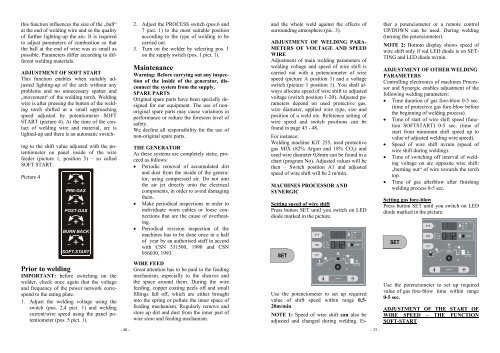
this function influences the size of the „ball“at the end of welding wire and so the qualityof further lighting-up the arc. It is requiredto adjust parameters of combustion so thatthe ball at the end of wire was as small aspossible. Parameters differ according to differentwelding materials.ADJUSTMENT OF SOFT STARTThis function enables when suitably adjustedlighting-up of the arch without anyproblems and no unnecessary spatter and„movement“ of the welding torch. Weldingwire is after pressing the button of the weldingtorch shifted at a small approachingspeed adjusted by potentiometer SOFTSTART (picture 4). At the time of the contactof welding wire and material, arc islighted-up and there is an automatic switch-ing to the shift value adjusted with the potentiometeron panel inside of the wirefeeder (picture 1, position 5) – so calledSOFT START.Picture 42. Adjust the PROCESS switch (pos.6 and7 pict. 1) to the most suitable positionaccording to the type of welding to becarried out.3. Turn on the welder by selecting pos. 1on the supply switch (pos. 1 pict. 1).MaintenanceWarning: Before carrying out any inspectionof the inside of the generator, disconnectthe system from the supply.SPARE PARTSOriginal spare parts have been specially designedfor our equipment. The use of nonoriginalspare parts may cause variations inperformance or reduce the foreseen level ofsafety.We decline all responsibility for the use ofnon-original spare parts.THE GENERATORAs these systems are completely static, proceedas follows:• Periodic removal of accumulated dirtand dust from the inside of the generator,using compressed air. Do not aimthe air jet directly onto the electricalcomponents, in order to avoid damagingthem.• Make periodical inspections in order toindividuate worn cables or loose connectionsthat are the cause of overheating.• Periodical revision inspection of themachines has to be done once in a halfof year by an authorised staff in accordwith CSN 331<strong>500</strong>, 1990 and CSN056030, 1993.and the whole weld against the effects ofsurrounding atmosphere (pic. 3).ADJUSTMENT OF WELDING PARA-METERS OF VOLTAGE AND SPEEDWIREAdjustment of main welding parameters ofwelding voltage and speed of wire shift iscarried out with a potenciometer of wirespeed (picture A position 1) and a voltageswitch (picture 1 position 1). You shall alwaysallocate speed of wire shift to adjustedvoltage (switch position 1-20). Adjusted parametersdepend on used protective gas,wire diameter, applied wire type, size andposition of a weld etc. Reference setting ofwire speed and switch positions can befound in page 43 - 48.For instance:Welding machine KIT 255, used protectivegas MIX (82% Argon and 18% CO 2 ) andused wire diameter 0,8mm can be found in achart (program No). Adjusted values will bethen – Switch position A1 and adjustedspeed of wire shift will be 2 m/min.MACHINES PROCESSOR ANDSYNERGICSetting speed of wire shiftPress button SET until you switch on LEDdiode marked in the picture.ther a potenciometer or a remote controlUP/DOWN can be used. During welding(turning the potenciometer).NOTE 2: Bottom display shows speed ofwire shift only if red LED diode is on SET-TING and LED diode m/min.ADJUSTMENT OF OTHER WELDINGPARAMETERSControlling electronics of machines Processorand Synergic enables adjustment of thefollowing welding parameters:• Time duration of gas fore-blow 0-5 sec.(time of protective gas fore-blow beforethe beginning of welding process).• Time of start of wire shift speed (functionSOFTSTART) 0-5 sec. (time ofstart from minimum shift speed up tovalue of adjusted welding wire speed).• Speed of wire shift m/min (speed ofwire shift during welding).• Time of switching off interval of weldingvoltage on arc opposite wire shift:„burning out“ of wire towards the torchtop.• Time of gas afterblow after finishingwelding process 0-5 sec.Setting gas fore-blowPress button SET until you switch on LEDdiode marked in the picture.Prior to weldingIMPORTANT: before switching on thewelder, check once again that the voltageand frequency of the power network correspondto the rating plate.1. Adjust the welding voltage using theswitch (pos. 2,4 pict. 1) and weldingcurrent/wire speed using the panel potentiometer(pos. 5 pict. 1).WIRE FEEDGreat attention has to be paid to the feedingmechanism, especially to the sheaves andthe space around them. During the wirefeeding, copper coating peels off and smallfillings fall off, which are either broughtinto the spring or pollute the inner space offeeding mechanism. Regularly remove andstore up dirt and dust from the inner part ofwire store and feeding mechanism.Use the potenciometer to set up requiredvalue of shift speed within range 0,5-20m/min.NOTE 1: Speed of wire shift can also beadjusted and changed during welding. Ei-Use the potenciometer to set up requiredvalue of gas fore-blow time within range0-5 sec.ADJUSTMENT OF THE START OFWIRE SPEED – THE FUNCTIONSOFT-START- 40 -- 33 -