DTC C0210/33 RIGHT REAR SPEED SENSOR ... - Highlander Club
DTC C0210/33 RIGHT REAR SPEED SENSOR ... - Highlander Club
DTC C0210/33 RIGHT REAR SPEED SENSOR ... - Highlander Club
- No tags were found...

You also want an ePaper? Increase the reach of your titles
YUMPU automatically turns print PDFs into web optimized ePapers that Google loves.
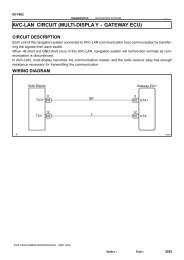
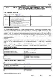
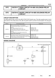
05-798DIAGNOSTICS-ABS WITH EBD & BA & TRAC & VSC SYSTEM21R142054WD:(a) Disconnect the rear speed sensor connector.(b) Measure the resistance according to the value(s) in thetable below.Standard:(c)Tester ConnectionSpecified Condition1 - 2 0.9 to 1.3 kΩ at 25 CMeasure the resistance according to the value(s) in thetable below.Standard:Tester ConnectionSpecified Condition1 - Body ground 10 kΩ or higher2 - Body ground 10 kΩ or higherNOTICE:Check the speed sensor signal after replacement(see page 05-765 ).NGREPLACE <strong>REAR</strong> <strong>SPEED</strong> <strong>SENSOR</strong>(SEE PAGE 32-37 )OK4 CHECK HARNESS AND CONNECTOR(<strong>REAR</strong> <strong>SPEED</strong> <strong>SENSOR</strong> - SKID CONTROLECU)Skid Control ECU S27(harness side connector)RR+ RL-RR- RL+Skid Control Sensor(harness side connector)A24A25(a)(b)Disconnect the skid control ECU connector and the skidcontrol sensor connector.Measure the resistance according to the value(s) in thetable below.Standard:LH:Tester ConnectionSpecified ConditionS27-20 (RL+) - A24-1 (RL+) Below 1 ΩS27-6 (RL-) - A24-2 (RL-) Below 1 ΩRH:Tester ConnectionSpecified ConditionS27-5 (RR+) - A25-1 (RR+) Below 1 ΩRL-RL+RR-RR+G26241(c)S27-19 (RR-) - A25-2 (RR-) Below 1 ΩMeasure the resistance according to the value(s) in thetable below.Standard:LH:Tester ConnectionSpecified ConditionS27-20 (RL+) - Body ground 10 kΩ or higherS27-6 (RL-) - Body ground 10 kΩ or higherRH:Tester ConnectionSpecified ConditionS27-5 (RR+) - Body ground 10 kΩ or higherS27-19 (RR-) - Body ground 10 kΩ or higherAuthor:Date:988
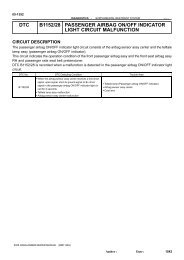
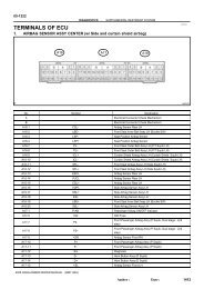
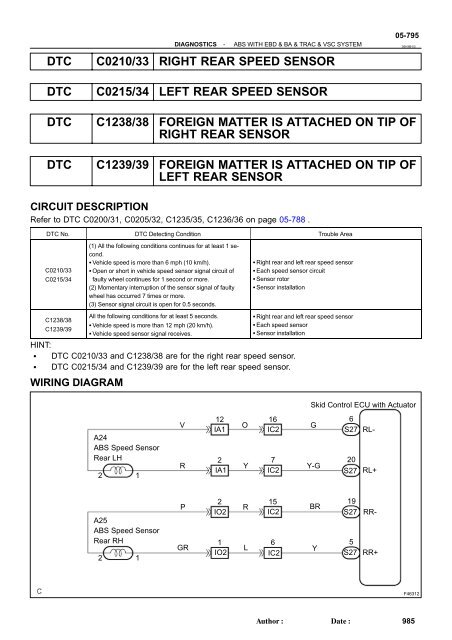
DIAGNOSTICS-ABS WITH EBD & BA & TRAC & VSC SYSTEM05-799NG REPAIR OR REPLACE HARNESS ORCONNECTOROK5 INSPECT <strong>SPEED</strong> <strong>SENSOR</strong> AND <strong>SENSOR</strong> ROTOR SERRATIONSNormal Signal Waveform1 V / Division 2 m/s / Division GNDW04200INSPECTION USING OSCILLOSCOPE(a) Connect the oscilloscope to terminals RR+ - RR- or RL+- RL- of the skid control ECU.(b) Drive the vehicle at approximately 19 mph (30 km/h), andcheck the signal waveform.OK:A waveform as shown in a figure should be output.HINT: As the vehicle speed (wheel revolution speed) increases,a cycle of the waveform narrows and the fluctuation in theoutput voltage becomes greater. When noise is identified in the waveform on the oscilloscope,error signals are generated due to the speed sensorrotor’s scratches, looseness or foreign matter attachedto it.NG Go to step 6OKREPLACE <strong>REAR</strong> <strong>SPEED</strong> <strong>SENSOR</strong> (SEE PAGE 32-42 (FF) OR 32-44 (4WD))Author:Date:989
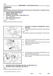
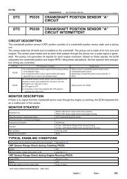
05-800DIAGNOSTICS-ABS WITH EBD & BA & TRAC & VSC SYSTEM6 INSPECT <strong>REAR</strong> <strong>SPEED</strong> <strong>SENSOR</strong> INSTALLATIONSkid Control Sensor2WD:(a) Check the sensor installation.OK:There is no clearance between the sensor and rearaxle carrier.OKNGF10178OK8.0 N⋅m(82 kgf⋅cm,71 in.⋅lbf)No ClearnaceNGBR37954WD:(a) Check the speed sensor installation.OK:There is no clearance between the sensor and rearaxle carrier.The installation bolt is tightened properly.Torque: 8.0 N⋅m (82 kgf⋅cm, 71 in.⋅lbf)NOTICE:Check the speed sensor signal after replacement(see page 05-765 ).NGREPLACE <strong>REAR</strong> <strong>SPEED</strong> <strong>SENSOR</strong>(SEE PAGE 32-42 (FF) OR 32-44 (4WD))OKAuthor:Date:990
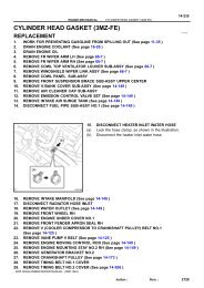
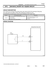
DIAGNOSTICS-ABS WITH EBD & BA & TRAC & VSC SYSTEM05-8017 INSPECT <strong>SPEED</strong> <strong>SENSOR</strong> ROTOR AND <strong>SENSOR</strong> TIP2WD:(a) Remove the skid control sensor (see page 32-42 ).(b) Check the sensor tip.OK:No scratches or foreign matter on the sensor tip.4WD:(a) Remove the rear speed sensor (See page 32-44 ).(b) Check the sensor tip.OK:No scratches or foreign matter on the sensor tip.Sensor Rotor2WD:(a) Check the sensor rotor serrations.OK:No scratches, missing teeth or foreign matter on therotor.F08575Sensor RotorR009484WD:(a) Remove the rear drive shaft (See page 30-45 ).(b) Check the sensor rotor serrations.OK:No scratches, missing teeth or foreign matter.HINT:If foreign matter is attached, remove it and after reassembling,check the output waveform.NOTICE:Check the speed sensor signal after the replacement(see page 05-765 ).NG CLEAN OR REPLACE <strong>SPEED</strong> <strong>SENSOR</strong> AND<strong>SENSOR</strong> ROTOR SERRATIONSOKREPLACE ABS & TRACTION ACTUATOR ASSY (SEE PAGE 32-37 )Author:Date:991