Intel Pentium III Processor for the SC242 at 450 MHz to 1.0 GHz
Intel Pentium III Processor for the SC242 at 450 MHz to 1.0 GHz
Intel Pentium III Processor for the SC242 at 450 MHz to 1.0 GHz

You also want an ePaper? Increase the reach of your titles
YUMPU automatically turns print PDFs into web optimized ePapers that Google loves.
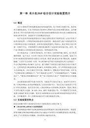
<strong>Intel</strong> ® <strong>Pentium</strong> ® <strong>III</strong> <strong>Processor</strong> <strong>for</strong> <strong>the</strong><strong>SC242</strong> <strong>at</strong> <strong>450</strong> <strong>MHz</strong> <strong>to</strong> <strong>1.0</strong> <strong>GHz</strong>D<strong>at</strong>asheetProduct Fe<strong>at</strong>ures■ Available in <strong>1.0</strong>B <strong>GHz</strong>, 933, 866, 800EB,733, 667, 600B, 600EB, 533B, and 533EB<strong>MHz</strong> speeds support a 133 <strong>MHz</strong> systembus (‘B’ denotes support <strong>for</strong> a 133 <strong>MHz</strong>system bus where a processor is available<strong>at</strong> <strong>the</strong> same specific core frequency inseper<strong>at</strong>e 100 <strong>MHz</strong> and 133 <strong>MHz</strong> Front SideBus versions; ‘E’ denotes support <strong>for</strong>Advanced Transfer Cache and AdvancedSystem Buffering)■ Available in <strong>1.0</strong> <strong>GHz</strong>, 850, 800, 750, 700,650, 600E, 600, 550E, 550, 500, and<strong>450</strong> <strong>MHz</strong> speeds support a 100 <strong>MHz</strong>system bus (‘E’ denotes support <strong>for</strong>Advanced Transfer Cache and AdvancedSystem Buffering)■ Available in versions th<strong>at</strong> incorpor<strong>at</strong>e256-KB Advanced Transfer Cache (on-die,full speed Level 2 (L2) cache with ErrorCorrecting Code (ECC)) or versions th<strong>at</strong>incorpor<strong>at</strong>e a discrete, half-speed, 512-KBin-package L2 cache with ECC■ Dual Independent Bus (DIB) architectureincreases bandwidth and per<strong>for</strong>mance oversingle-bus processors■■■■■■■■■■Internet Streaming SIMD Extensions <strong>for</strong>enhanced video, sound and 3Dper<strong>for</strong>manceBinary comp<strong>at</strong>ible with applic<strong>at</strong>ionsrunning on previous members of <strong>the</strong> <strong>Intel</strong>microprocessor lineDynamic execution micro architecturePower Management capabilities—System Management mode—Multiple low-power st<strong>at</strong>es<strong>Intel</strong> <strong>Processor</strong> Serial NumberOptimized <strong>for</strong> 32-bit applic<strong>at</strong>ions runningon advanced 32-bit oper<strong>at</strong>ing systemsSingle Edge Contact Cartridge (S.E.C.C.)and S.E.C.C.2 packaging technology; <strong>the</strong>S.E.C. cartridges deliver high per<strong>for</strong>mancewith improved handling protection andsocketabilityIntegr<strong>at</strong>ed high per<strong>for</strong>mance 16 KBinstruction and 16-KB d<strong>at</strong>a, nonblocking,level one cacheEnables systems which are scaleable up <strong>to</strong>two processorsError-correcting code <strong>for</strong> System Bus d<strong>at</strong>aThe <strong>Intel</strong> ® <strong>Pentium</strong> ® <strong>III</strong> processor is designed <strong>for</strong> high-per<strong>for</strong>mance desk<strong>to</strong>ps and <strong>for</strong>workst<strong>at</strong>ions and servers. It is binary comp<strong>at</strong>ible with previous <strong>Intel</strong> Architecture processors.The <strong>Pentium</strong> <strong>III</strong> processor provides gre<strong>at</strong> per<strong>for</strong>mance <strong>for</strong> applic<strong>at</strong>ions running on advancedoper<strong>at</strong>ing systems such as Microsoft Windows* 98, Windows NT* and UNIX*. This is achievedby integr<strong>at</strong>ing <strong>the</strong> best <strong>at</strong>tributes of <strong>Intel</strong> processors—<strong>the</strong> dynamic execution, Dual IndependentBus architecture plus <strong>Intel</strong> ® MMX technology and Internet Streaming SIMD Extensions—bringing a new level of per<strong>for</strong>mance <strong>for</strong> systems buyers. The<strong>Pentium</strong> <strong>III</strong> processor is scaleable <strong>to</strong>two processors in a multiprocessor system and extends <strong>the</strong> power of <strong>the</strong> <strong>Intel</strong> ® <strong>Pentium</strong> ® IIprocessor with per<strong>for</strong>mance headroom <strong>for</strong> business media, communic<strong>at</strong>ion and internetcapabilities. Systems based on <strong>Pentium</strong> <strong>III</strong> processors also include <strong>the</strong> l<strong>at</strong>est fe<strong>at</strong>ures <strong>to</strong> simplifysystem management and lower <strong>the</strong> cost of ownership <strong>for</strong> large and small business environments.The <strong>Pentium</strong> <strong>III</strong> processor offers gre<strong>at</strong> per<strong>for</strong>mance <strong>for</strong> <strong>to</strong>day’s and <strong>to</strong>morrow’s applic<strong>at</strong>ions.<strong>SC242</strong> / SECC2 PackageDocument Number: 244452-009July 2002
INFORMATION IN THIS DOCUMENT IS PROVIDED IN CONNECTION WITH INTEL ® PRODUCTS. NO LICENSE, EXPRESS OR IMPLIED, BYESTOPPEL OR OTHERWISE, TO ANY INTELLECTUAL PROPERTY RIGHTS IS GRANTED BY THIS DOCUMENT. EXCEPT AS PROVIDED ININTEL'S TERMS AND CONDITIONS OF SALE FOR SUCH PRODUCTS, INTEL ASSUMES NO LIABILITY WHATSOEVER, AND INTEL DISCLAIMSANY EXPRESS OR IMPLIED WARRANTY, RELATING TO SALE AND/OR USE OF INTEL PRODUCTS INCLUDING LIABILITY OR WARRANTIESRELATING TO FITNESS FOR A PARTICULAR PURPOSE, MERCHANTABILITY, OR INFRINGEMENT OF ANY PATENT, COPYRIGHT OR OTHERINTELLECTUAL PROPERTY RIGHT. <strong>Intel</strong> products are not intended <strong>for</strong> use in medical, life saving, or life sustaining applic<strong>at</strong>ions.<strong>Intel</strong> may make changes <strong>to</strong> specific<strong>at</strong>ions and product descriptions <strong>at</strong> any time, without notice.Designers must not rely on <strong>the</strong> absence or characteristics of any fe<strong>at</strong>ures or instructions marked “reserved” or “undefined”. <strong>Intel</strong> reserves <strong>the</strong>se <strong>for</strong>future definition and shall have no responsibility wh<strong>at</strong>soever <strong>for</strong> conflicts or incomp<strong>at</strong>ibilities arising from future changes <strong>to</strong> <strong>the</strong>m.The <strong>Pentium</strong> ® <strong>III</strong> processor may contain design defects or errors known as err<strong>at</strong>a which may cause <strong>the</strong> product <strong>to</strong> devi<strong>at</strong>e from publishedspecific<strong>at</strong>ions. Current characterized err<strong>at</strong>a are available on request.Contact your local <strong>Intel</strong> sales office or your distribu<strong>to</strong>r <strong>to</strong> obtain <strong>the</strong> l<strong>at</strong>est specific<strong>at</strong>ions and be<strong>for</strong>e placing your product order.Copies of documents which have an ordering number and are referenced in this document, or o<strong>the</strong>r <strong>Intel</strong> liter<strong>at</strong>ure may be obtained by calling 1-800-548-4725 or by visiting <strong>Intel</strong>'s website <strong>at</strong> http://www.intel.com.<strong>Intel</strong>, <strong>Pentium</strong>, Celeron, MMX, and <strong>the</strong> <strong>Intel</strong> logo are trademarks or registered trademarks of <strong>Intel</strong> Corpor<strong>at</strong>ion or its subsidiaries in <strong>the</strong> United St<strong>at</strong>esand o<strong>the</strong>r countries.*O<strong>the</strong>r names and brands may be claimed as <strong>the</strong> property of o<strong>the</strong>rs.Copyright © 2002, <strong>Intel</strong> Corpor<strong>at</strong>ionD<strong>at</strong>asheet
Contents<strong>1.0</strong> Introduction.........................................................................................................................91.1 Terminology.........................................................................................................101.1.1 S.E.C.C.2 and S.E.C.C. Packaged <strong>Processor</strong> Terminology ..................101.1.2 <strong>Processor</strong> Naming Convention...............................................................111.2 Rel<strong>at</strong>ed Documents.............................................................................................122.0 Electrical Specific<strong>at</strong>ions....................................................................................................132.1 <strong>Processor</strong> System Bus and V REF ........................................................................132.2 Clock Control and Low Power St<strong>at</strong>es..................................................................142.2.1 Normal St<strong>at</strong>e—St<strong>at</strong>e 1 ...........................................................................152.2.2 Au<strong>to</strong>HALT Powerdown St<strong>at</strong>e—St<strong>at</strong>e 2...................................................152.2.3 S<strong>to</strong>p-Grant St<strong>at</strong>e—St<strong>at</strong>e 3 .....................................................................152.2.4 HALT/Grant Snoop St<strong>at</strong>e—St<strong>at</strong>e 4 ........................................................162.2.5 Sleep St<strong>at</strong>e—St<strong>at</strong>e 5..............................................................................162.2.6 Deep Sleep St<strong>at</strong>e—St<strong>at</strong>e 6 ....................................................................162.2.7 Clock Control..........................................................................................172.3 Power and Ground Pins ......................................................................................172.4 Decoupling Guidelines ........................................................................................172.4.1 <strong>Processor</strong> VCC CORE Decoupling............................................................182.4.2 <strong>Processor</strong> System Bus AGTL+ Decoupling............................................182.5 <strong>Processor</strong> System Bus Clock and <strong>Processor</strong> Clocking .......................................182.6 Voltage Identific<strong>at</strong>ion ...........................................................................................182.7 <strong>Processor</strong> System Bus Unused Pins...................................................................202.8 <strong>Processor</strong> System Bus Signal Groups ................................................................202.8.1 Asynchronous vs. Synchronous <strong>for</strong> System Bus Signals.......................212.8.2 System Bus Frequency Select Signal (BSEL0)......................................222.9 Test Access Port (TAP) Connection....................................................................232.10 Maximum R<strong>at</strong>ings................................................................................................242.11 <strong>Processor</strong> DC Specific<strong>at</strong>ions...............................................................................252.12 AGTL+ System Bus Specific<strong>at</strong>ions .....................................................................322.13 System Bus AC Specific<strong>at</strong>ions ............................................................................323.0 Signal Quality Specific<strong>at</strong>ions ............................................................................................403.1 BCLK, PICCLK, and PWRGOOD Signal Quality Specific<strong>at</strong>ions andMeasurement Guidelines ....................................................................................403.2 AGTL+ and Non-AGTL+ Overshoot/Undershoot Specific<strong>at</strong>ions andMeasurement Guidelines ....................................................................................413.2.1 Overshoot/Undershoot Magnitude .........................................................413.2.2 Overshoot/Undershoot Pulse Dur<strong>at</strong>ion...................................................423.2.3 Overshoot/Undershoot Activity Fac<strong>to</strong>r....................................................423.2.4 Reading Overshoot/Undershoot Specific<strong>at</strong>ion Tables............................433.2.5 Determining If a System Meets <strong>the</strong> Overshoot/UndershootSpecific<strong>at</strong>ions .........................................................................................443.3 AGTL+ and Non-AGTL+ Ringback Specific<strong>at</strong>ions and MeasurementGuidelines ...........................................................................................................463.3.1 Settling Limit Guideline...........................................................................48D<strong>at</strong>asheet 3
4.0 Thermal Specific<strong>at</strong>ions and Design Consider<strong>at</strong>ions......................................................... 494.1 Thermal Specific<strong>at</strong>ions........................................................................................ 504.1.1 Thermal Diode........................................................................................ 535.0 S.E.C.C. and S.E.C.C.2 Mechanical Specific<strong>at</strong>ions......................................................... 545.1 S.E.C.C. Mechanical Specific<strong>at</strong>ions.................................................................... 545.2 S.E.C.C.2 Mechanical Specific<strong>at</strong>ion.................................................................... 615.3 S.E.C.C.2 Structural Mechanical Specific<strong>at</strong>ion ................................................... 675.4 <strong>Processor</strong> Package M<strong>at</strong>erials In<strong>for</strong>m<strong>at</strong>ion .......................................................... 695.5 <strong>Intel</strong> ® <strong>Pentium</strong> ® <strong>III</strong> <strong>Processor</strong> Signal Listing........................................................ 695.6 <strong>Intel</strong> ® <strong>Pentium</strong> ® <strong>III</strong> <strong>Processor</strong> Core Pad <strong>to</strong> Substr<strong>at</strong>e Via Assignments .............. 765.6.1 <strong>Processor</strong> Core Pad Via Assignments (CPUID=067xh)......................... 765.6.2 <strong>Processor</strong> Core Signal Assignments (CPUID=067xh) ........................... 765.6.3 <strong>Processor</strong> Core Pad Via Assignments (CPUID=068xh)......................... 876.0 Boxed <strong>Processor</strong> Specific<strong>at</strong>ions....................................................................................... 886.1 Introduction .........................................................................................................886.2 Fan He<strong>at</strong>sink Mechanical Specific<strong>at</strong>ions............................................................. 886.2.1 <strong>Intel</strong> ® Boxed <strong>Processor</strong> Fan He<strong>at</strong>sink Dimensions ................................ 886.2.2 <strong>Intel</strong> ® Boxed <strong>Processor</strong> Fan He<strong>at</strong>sink Weight........................................ 906.2.3 <strong>Intel</strong> ® Boxed <strong>Processor</strong> Retention Mechanism....................................... 906.3 Fan He<strong>at</strong>sink Electrical Requirements ................................................................ 916.3.1 Fan He<strong>at</strong>sink Power Supply................................................................... 916.4 Fan He<strong>at</strong>sink Thermal Specific<strong>at</strong>ions..................................................................926.4.1 <strong>Intel</strong> ® Boxed <strong>Processor</strong> Cooling Requirements...................................... 927.0 <strong>Intel</strong> ® <strong>Pentium</strong> ® <strong>III</strong> <strong>Processor</strong> Signal Description ............................................................. 937.1 Alphabetical Signals Reference .......................................................................... 937.2 Signal Summaries ............................................................................................. 1004 D<strong>at</strong>asheet
Figures1 Second Level (L2) Cache Implement<strong>at</strong>ion ...........................................................92 AGTL+ Bus Topology..........................................................................................143 S<strong>to</strong>p Clock St<strong>at</strong>e Machine ...................................................................................144 BSEL[1:0] Example <strong>for</strong> a 100 <strong>MHz</strong> System Design (100 <strong>MHz</strong> <strong>Processor</strong>Installed)..............................................................................................................225 BSEL[1:0] Example <strong>for</strong> a 100/133 <strong>MHz</strong> Capable System(100 <strong>MHz</strong> <strong>Processor</strong> Installed) ............................................................................236 BSEL[1:0] Example <strong>for</strong> a 100/133 <strong>MHz</strong> Capable System(133 <strong>MHz</strong> <strong>Processor</strong> Installed) ............................................................................237 BCLK, PICCLK, and TCK Generic Clock Wave<strong>for</strong>m...........................................378 System Bus Valid Delay Timings ........................................................................389 System Bus Setup and Hold Timings..................................................................3810 System Bus Reset and Configur<strong>at</strong>ion Timings....................................................3811 Power-On Reset and Configur<strong>at</strong>ion Timings.......................................................3912 Test Timings (TAP Connection) ..........................................................................3913 Test Reset Timings .............................................................................................3914 BCLK and PICCLK Generic Clock Wave<strong>for</strong>m .....................................................4015 Maximum Acceptable AGTL+ and Non-AGTL+ Overshoot/UndershootWave<strong>for</strong>m ............................................................................................................4616 Low <strong>to</strong> High AGTL+ and Non-AGTL+ Receiver Ringback Tolerance .................4817 Signal Overshoot/Undershoot, Settling Limit, and Ringback...............................4818 S.E.C.Cartridge — 3-Dimensional View..............................................................4919 S.E.C.Cartridge 2 — Substr<strong>at</strong>e View ..................................................................5020 <strong>Processor</strong> Functional Die Layout (CPUID=0686h)..............................................5221 <strong>Processor</strong> Functional Die Layout (up <strong>to</strong> CPUID=0683h).....................................5222 S.E.C.C. Packaged <strong>Processor</strong> — Multiple Views................................................5423 S.E.C.C. Packaged <strong>Processor</strong> — Extended Thermal Pl<strong>at</strong>e SideDimensions..........................................................................................................5524 S.E.C.C. Packaged <strong>Processor</strong> — Bot<strong>to</strong>m View Dimensions...............................5525 S.E.C.C. Packaged <strong>Processor</strong> — L<strong>at</strong>ch Arm, Extended Thermal Pl<strong>at</strong>e Lug,and Cover Lug Dimensions .................................................................................5626 S.E.C.C. Packaged <strong>Processor</strong> — L<strong>at</strong>ch Arm, Extended Thermal Pl<strong>at</strong>e,and Cover Detail Dimensions (Reference Dimensions Only)..............................5727 S.E.C.C. Packaged <strong>Processor</strong> — Extended Thermal Pl<strong>at</strong>e AttachmentDetail Dimensions ...............................................................................................5829 S.E.C.C. Packaged <strong>Processor</strong> Substr<strong>at</strong>e — Edge Finger ContactDimensions..........................................................................................................5928 S.E.C.C. Packaged <strong>Processor</strong> — Extended Thermal Pl<strong>at</strong>e AttachmentDetail Dimensions, Continued .............................................................................5930 S.E.C.C. Packaged <strong>Processor</strong> Substr<strong>at</strong>e — Edge Finger ContactDimensions, Detail A ...........................................................................................6031 <strong>Intel</strong> ® <strong>Pentium</strong>® <strong>III</strong> <strong>Processor</strong> Markings (S.E.C.C. Packaged <strong>Processor</strong>)...........6032 S.E.C.C.2 Packaged <strong>Processor</strong> — Multiple Views..............................................6133 S.E.C.C.2 Packaged <strong>Processor</strong> Assembly — Primary View...............................6234 S.E.C.C.2 Packaged <strong>Processor</strong> Assembly — Cover View with Dimensions ......6235 S.E.C.C.2 Packaged <strong>Processor</strong> Assembly — He<strong>at</strong>sink Attach Boss Section.....6336 S.E.C.C.2 Packaged <strong>Processor</strong> Assembly — Side View ....................................6337 Detail View of Cover in <strong>the</strong> Vicinity of <strong>the</strong> Substr<strong>at</strong>e Attach Fe<strong>at</strong>ures.................6338 S.E.C.C.2 Packaged <strong>Processor</strong> Substr<strong>at</strong>e — Edge Finger ContactDimensions..........................................................................................................64D<strong>at</strong>asheet 5
39 S.E.C.C.2 Packaged <strong>Processor</strong> Substr<strong>at</strong>e — Edge Finger ContactDimensions (Detail A) ......................................................................................... 6440 S.E.C.C.2 Packaged <strong>Processor</strong> Substr<strong>at</strong>e (CPUID=067xh) —Keep-In Zones..................................................................................................... 6541 S.E.C.C.2 Packaged <strong>Processor</strong> Substr<strong>at</strong>e (CPUID=068xh) —Keep-In Zones..................................................................................................... 6542 S.E.C.C.2 Packaged <strong>Processor</strong> Substr<strong>at</strong>e (CPUID=067xh) —Keep-Out Zone.................................................................................................... 6643 S.E.C.C.2 Packaged <strong>Processor</strong> Substr<strong>at</strong>e (CPUID=068xh) —Keep-Out Zone.................................................................................................... 6644 <strong>Intel</strong> ® <strong>Pentium</strong>® <strong>III</strong> <strong>Processor</strong> Markings (S.E.C.C.2 Package) ........................... 6745 Substr<strong>at</strong>e Deflection away from He<strong>at</strong>sink ........................................................... 6746 Substr<strong>at</strong>e Deflection <strong>to</strong>ward <strong>the</strong> He<strong>at</strong>sink ........................................................... 6847 S.E.C.C.2 Packaged <strong>Processor</strong> Specific<strong>at</strong>ions................................................... 6848 <strong>Processor</strong> Core Pad Via Assignments ................................................................ 7649 <strong>Intel</strong> ® <strong>Pentium</strong> ® <strong>III</strong> <strong>Processor</strong> S.E.C.C. 2 Via Map.............................................. 8750 Boxed <strong>Intel</strong> ® <strong>Pentium</strong> ® <strong>III</strong> <strong>Processor</strong> in <strong>the</strong> S.E.C.C.2 Packaging(Fan Power Cable Not Shown) ........................................................................... 8851 Side View Space Requirements <strong>for</strong> <strong>the</strong> <strong>Intel</strong> ® Boxed <strong>Processor</strong> withS.E.C.C.2 Packaging .......................................................................................... 8952 Front View Space Requirements <strong>for</strong> <strong>the</strong> <strong>Intel</strong> ® Boxed <strong>Processor</strong> withS.E.C.C.2 Packaging .......................................................................................... 8953 Top View Air Space Requirements <strong>for</strong> <strong>the</strong> <strong>Intel</strong> ® Boxed <strong>Processor</strong>.................... 9054 <strong>Intel</strong> ® Boxed <strong>Processor</strong> Fan He<strong>at</strong>sink Power Cable Connec<strong>to</strong>r Description....... 9155 Recommended Baseboard Power Header Placement Rel<strong>at</strong>ive <strong>to</strong> FanPower Connec<strong>to</strong>r and <strong>Intel</strong> ® <strong>Pentium</strong> ® <strong>III</strong> <strong>Processor</strong>........................................... 92Tables1 <strong>Processor</strong> Identific<strong>at</strong>ion....................................................................................... 112 Rel<strong>at</strong>ed Documents ............................................................................................123 Voltage Identific<strong>at</strong>ion Definition........................................................................... 194 System Bus Signal Groups ................................................................................. 215 Frequency Select Truth Table <strong>for</strong> BSEL[1:0] ...................................................... 226 Absolute Maximum R<strong>at</strong>ings (CPUID=067xh)...................................................... 247 Absolute Maximum R<strong>at</strong>ings (CPUID=068xh)...................................................... 258 Voltage and Current Specific<strong>at</strong>ions..................................................................... 269 AGTL+ Signal Groups DC Specific<strong>at</strong>ions............................................................3110 Non-AGTL+ Signal Group DC Specific<strong>at</strong>ions...................................................... 3111 AGTL+ Bus Specific<strong>at</strong>ions .................................................................................. 3212 System Bus AC Specific<strong>at</strong>ions (Clock) <strong>at</strong> <strong>Processor</strong> Core Pins ......................... 3313 Valid System Bus, Core Frequency, and Cache Bus Frequencies.....................3414 System Bus AC Specific<strong>at</strong>ions (AGTL+ Signal Group) <strong>at</strong> <strong>the</strong> <strong>Processor</strong>Core Pins ............................................................................................................ 3515 System Bus AC Specific<strong>at</strong>ions (CMOS Signal Group) <strong>at</strong> <strong>the</strong> <strong>Processor</strong>Core Pins ............................................................................................................ 3516 System Bus AC Specific<strong>at</strong>ions (Reset Conditions) ............................................. 3517 System Bus AC Specific<strong>at</strong>ions (APIC Clock and APIC I/O) <strong>at</strong> <strong>the</strong> <strong>Processor</strong>Core Pins ............................................................................................................ 366 D<strong>at</strong>asheet
18 System Bus AC Specific<strong>at</strong>ions (TAP Connection) <strong>at</strong> <strong>the</strong> <strong>Processor</strong>Core Pins.............................................................................................................3619 BCLK, PICCLK, and PWRGOOD Signal Quality Specific<strong>at</strong>ions <strong>at</strong> <strong>the</strong><strong>Processor</strong> Core ...................................................................................................4020 100 <strong>MHz</strong> AGTL+ Signal Group Overshoot/Undershoot Tolerance .....................4421 133 <strong>MHz</strong> AGTL+ Signal Group Overshoot/Undershoot Tolerance .....................4522 33 <strong>MHz</strong> Non-AGTL+ Signal Group Overshoot/Undershoot Tolerance................4523 Signal Ringback Specific<strong>at</strong>ions <strong>for</strong> Signal Simul<strong>at</strong>ion .........................................4724 AGTL+ and Non-AGTL+ Signal Groups Ringback Tolerance Specific<strong>at</strong>ions......4725 Thermal Specific<strong>at</strong>ions <strong>for</strong> S.E.C.C. Packaged <strong>Processor</strong>s................................5026 Thermal Specific<strong>at</strong>ions <strong>for</strong> S.E.C.C.2 Packaged <strong>Processor</strong>s..............................5127 Thermal Diode Parameters .................................................................................5328 Thermal Diode Interface......................................................................................5329 Description Table <strong>for</strong> <strong>Processor</strong> Markings (S.E.C.C. Packaged <strong>Processor</strong>).......6130 Description Table <strong>for</strong> <strong>Processor</strong> Markings (S.E.C.C.2 Packaged <strong>Processor</strong>).....6731 S.E.C.C.2 Pressure Specific<strong>at</strong>ions......................................................................6832 S.E.C.C. M<strong>at</strong>erials...............................................................................................6933 S.E.C.C.2 M<strong>at</strong>erials.............................................................................................6934 Signal Listing in Order by Pin Number ................................................................7035 Signal Listing in Order by Signal Name...............................................................7336 Via Listing in Order by Signal Name ...................................................................7737 Via Listing in Order by VIA Loc<strong>at</strong>ion....................................................................8238 <strong>Intel</strong> ® Boxed <strong>Processor</strong> Fan He<strong>at</strong>sink Sp<strong>at</strong>ial Dimensions .................................9039 Fan He<strong>at</strong>sink Power and Signal Specific<strong>at</strong>ions...................................................9140 Baseboard Fan Power Connec<strong>to</strong>r Loc<strong>at</strong>ion ........................................................9241 Signal Description ...............................................................................................9342 Output Signals...................................................................................................10043 Input Signals......................................................................................................10044 Input/Output Signals (Single Driver)..................................................................10145 Input/Output Signals (Multiple Driver) ...............................................................101D<strong>at</strong>asheet 7
Revision His<strong>to</strong>ryRevision Description D<strong>at</strong>e-009 • Removed 1.13 <strong>GHz</strong> processor frequency. Minor edits <strong>for</strong> clarity. July 20028 D<strong>at</strong>asheet
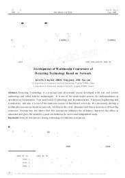
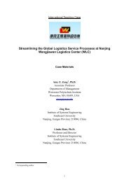
Introduction<strong>1.0</strong> IntroductionThe <strong>Intel</strong> ® <strong>Pentium</strong> ® <strong>III</strong> processor is <strong>the</strong> next member of <strong>the</strong> P6 family, in <strong>the</strong> <strong>Intel</strong> ® IA-32processor line. Like <strong>the</strong> <strong>Intel</strong> ® <strong>Pentium</strong> ® II processor, <strong>the</strong> <strong>Pentium</strong> <strong>III</strong> processor implements <strong>the</strong>Dynamic Execution microarchitecture - a unique combin<strong>at</strong>ion of multiple branch prediction, d<strong>at</strong>aflow analysis, and specul<strong>at</strong>ive execution. This enables <strong>the</strong>se processors <strong>to</strong> deliver higherper<strong>for</strong>mance than <strong>the</strong> <strong>Pentium</strong> processor, while maintaining binary comp<strong>at</strong>ibility with all previous<strong>Intel</strong> Architecture processors. The <strong>Pentium</strong> <strong>III</strong> processor also executes <strong>Intel</strong> ® MMX technologyinstructions <strong>for</strong> enhanced media and communic<strong>at</strong>ion per<strong>for</strong>mance just as it’s predecessor, <strong>the</strong><strong>Pentium</strong> II processor. The <strong>Pentium</strong> <strong>III</strong> processor executes Internet Streaming SIMD Extensions <strong>for</strong>enhanced flo<strong>at</strong>ing point and 3-D applic<strong>at</strong>ion per<strong>for</strong>mance. In addition, <strong>the</strong> <strong>Pentium</strong> <strong>III</strong> processorextends <strong>the</strong> concept of processor identific<strong>at</strong>ion with <strong>the</strong> addition of a processor serial number.Refer <strong>to</strong> <strong>the</strong> <strong>Intel</strong> ® <strong>Processor</strong> Serial Number applic<strong>at</strong>ion note (Document Number 245125) <strong>for</strong>more detailed in<strong>for</strong>m<strong>at</strong>ion. The <strong>Pentium</strong> <strong>III</strong> processor utilizes multiple low-power st<strong>at</strong>es such asAu<strong>to</strong>HALT, S<strong>to</strong>p-Grant, Sleep, and Deep Sleep <strong>to</strong> conserve power during idle times.The <strong>Pentium</strong> <strong>III</strong> processor utilizes <strong>the</strong> same multiprocessing system bus technology as <strong>the</strong><strong>Pentium</strong> II processor. This allows <strong>for</strong> a higher level of per<strong>for</strong>mance <strong>for</strong> both uni-processor and twowaymultiprocessor (2-way MP) systems. See <strong>the</strong> <strong>Intel</strong> ® <strong>Pentium</strong> ® <strong>III</strong> <strong>Processor</strong> Specific<strong>at</strong>ionUpd<strong>at</strong>e (Document Number 244453) <strong>for</strong> guidelines on which processors can be mixed in an MPsystem. Memory is cacheable <strong>for</strong> 4 GB of addressable memory space, allowing significan<strong>the</strong>adroom <strong>for</strong> desk<strong>to</strong>p systems.The <strong>Pentium</strong> <strong>III</strong> processor is available with two different second level (L2) cache implement<strong>at</strong>ions.The “Discrete” cache version (CPUID=067xh) uses commercially available parts <strong>for</strong> <strong>the</strong> L2 cache.The L2 cache is composed of an external (<strong>to</strong> processor silicon) TagRAM and burst pipelinedsynchronous st<strong>at</strong>ic RAM (BSRAM), as seen in Figure 1. The “Advanced Transfer Cache”(CPUID=068xh) does not use commercially available L2 cache parts. Its L2 cache resides entirelywithin <strong>the</strong> processor silicon, as seen in Figure 1. Refer <strong>to</strong> Table 1 <strong>to</strong> determine <strong>the</strong> L2 cacheimplement<strong>at</strong>ion <strong>for</strong> each <strong>Pentium</strong> <strong>III</strong> processor.<strong>Pentium</strong> <strong>III</strong> processors are offered in ei<strong>the</strong>r Single Edge Contact Cartridge (S.E.C.C.) or SingleEdge Contact Cartridge 2 (S.E.C.C.2) package technologies. The S.E.C.C. package has <strong>the</strong>following fe<strong>at</strong>ures: an extended <strong>the</strong>rmal pl<strong>at</strong>e, a cover, and a substr<strong>at</strong>e with an edge fingerconnection. The extended <strong>the</strong>rmal pl<strong>at</strong>e allows he<strong>at</strong>sink <strong>at</strong>tachment or cus<strong>to</strong>mized <strong>the</strong>rmalsolutions. The S.E.C.C.2 package has a cover and a substr<strong>at</strong>e with an edge finger connection. Thisallows <strong>the</strong> <strong>the</strong>rmal solutions <strong>to</strong> be placed directly on<strong>to</strong> <strong>the</strong> processor core package. The edge fingerconnection maintains socketability <strong>for</strong> system configur<strong>at</strong>ion. The edge finger connec<strong>to</strong>r is called<strong>the</strong> ‘<strong>SC242</strong> connec<strong>to</strong>r’ in this and o<strong>the</strong>r document<strong>at</strong>ion.Figure 1. Second Level (L2) Cache Implement<strong>at</strong>ionL2<strong>Processor</strong>Core Tag L2 <strong>Processor</strong>CoreDiscrete CacheAdvanced Transfer CacheD<strong>at</strong>asheet 9
Introduction1.1 TerminologyIn this document, a ‘#’ symbol after a signal name refers <strong>to</strong> an active low signal. This means th<strong>at</strong> asignal is in <strong>the</strong> active st<strong>at</strong>e (based on <strong>the</strong> name of <strong>the</strong> signal) when driven <strong>to</strong> a low level. Forexample, when FLUSH# is low, a flush has been requested. When NMI is high, a nonmaskableinterrupt has occurred. In <strong>the</strong> case of signals where <strong>the</strong> name does not imply an active st<strong>at</strong>e butdescribes part of a binary sequence (such as address or d<strong>at</strong>a), <strong>the</strong> ‘#’ symbol implies th<strong>at</strong> <strong>the</strong> signalis inverted. For example, D[3:0] = ‘HLHL’ refers <strong>to</strong> a hex ‘A’, and D[3:0]# = ‘LHLH’ also refers <strong>to</strong>a hex ‘A’ (H= High logic level, L= Low logic level).The term “system bus” refers <strong>to</strong> <strong>the</strong> interface between <strong>the</strong> processor, system core logic (a.k.a. <strong>the</strong>AGPset components), and o<strong>the</strong>r bus agents. The system bus is a multiprocessing interface <strong>to</strong>processors, memory, and I/O. The term “cache bus” refers <strong>to</strong> <strong>the</strong> interface between <strong>the</strong> processorand <strong>the</strong> L2 cache components (TagRAM and BSRAMs). The cache bus does NOT connect <strong>to</strong> <strong>the</strong>system bus, and is not visible <strong>to</strong> o<strong>the</strong>r agents on <strong>the</strong> system bus.1.1.1 S.E.C.C.2 and S.E.C.C. Packaged <strong>Processor</strong> TerminologyThe following terms are used often in this document and are explained here <strong>for</strong> clarific<strong>at</strong>ion:• <strong>Pentium</strong> ® <strong>III</strong> processor—The entire product including internal components, substr<strong>at</strong>e, coverand in S.E.C.C. packaged processors, an extended <strong>the</strong>rmal pl<strong>at</strong>e.• S.E.C.C.—The processor package technology called “Single Edge Contact Cartridge.”• S.E.C.C.2—The follow-on <strong>to</strong> S.E.C.C. processor package technology. This differs from itspredecessor in th<strong>at</strong> it has no extended <strong>the</strong>rmal pl<strong>at</strong>e, thus reducing <strong>the</strong>rmal resistance.• <strong>Processor</strong> substr<strong>at</strong>e—The FR4 board on which components are mounted inside <strong>the</strong> S.E.C.C.or S.E.C.C.2 packaged processor (with or without components <strong>at</strong>tached).• <strong>Processor</strong> core—The processor’s execution engine.• Extended Thermal Pl<strong>at</strong>e—This S.E.C.C. package fe<strong>at</strong>ure is <strong>the</strong> surface used <strong>to</strong> <strong>at</strong>tach ahe<strong>at</strong>sink or o<strong>the</strong>r <strong>the</strong>rmal solution <strong>to</strong> <strong>the</strong> processor.• Cover—The plastic casing th<strong>at</strong> covers <strong>the</strong> backside of <strong>the</strong> substr<strong>at</strong>e.• L<strong>at</strong>ch arms—An S.E.C.C. package fe<strong>at</strong>ure which can be used as a means <strong>for</strong> securing <strong>the</strong>processor in a retention mechanism.• OLGA - Organic Land Grid Array. This package technology permits <strong>at</strong>taching <strong>the</strong> he<strong>at</strong>sinkdirectly <strong>to</strong> <strong>the</strong> die.Additional terms referred <strong>to</strong> in this and o<strong>the</strong>r rel<strong>at</strong>ed document<strong>at</strong>ion:• <strong>SC242</strong>—The 242-contact slot connec<strong>to</strong>r (previously referred <strong>to</strong> as Slot 1 connec<strong>to</strong>r) th<strong>at</strong> <strong>the</strong>S.E.C.C. and S.E.C.C.2 plug in<strong>to</strong>, just as <strong>the</strong> <strong>Pentium</strong> ® Pro processor uses Socket 8.• Retention mechanism—A mechanical piece which holds <strong>the</strong> S.E.C.C. or S.E.C.C.2 packagedprocessor in <strong>the</strong> <strong>SC242</strong> connec<strong>to</strong>r.• He<strong>at</strong>sink support—The support pieces th<strong>at</strong> are mounted on <strong>the</strong> baseboard <strong>to</strong> provide addedsupport <strong>for</strong> he<strong>at</strong>sinks.• Keep-out zone—The area on or near an S.E.C.C. or S.E.C.C.2 packaged processor substr<strong>at</strong>eth<strong>at</strong> systems designs can not utilize.• Keep-in zone—The area of <strong>the</strong> center of an S.E.C.C. or S.E.C.C.2 packaged processorsubstr<strong>at</strong>e th<strong>at</strong> <strong>the</strong>rmal solutions may utilize.The L2 cache, TagRAM and BSRAM die, are industry design<strong>at</strong>ed names.10 D<strong>at</strong>asheet
Introduction1.1.2 <strong>Processor</strong> Naming ConventionA letter(s) is added <strong>to</strong> certain processors (e.g., 600B <strong>MHz</strong>) when <strong>the</strong> core frequency alone may notuniquely identify <strong>the</strong> processor. Below is a summary wh<strong>at</strong> <strong>the</strong> letter means as well as a table listingall <strong>Pentium</strong> <strong>III</strong> processors currently available.• “B” — 133 <strong>MHz</strong> System Bus Frequency• “E” — <strong>Processor</strong> with “Advanced Transfer Cache” (CPUID=068xh)Table 1.<strong>Processor</strong> Identific<strong>at</strong>ion<strong>Processor</strong>CoreFrequency(<strong>MHz</strong>)System BusFrequency(<strong>MHz</strong>)L2 Cache Size(Kbytes)L2 Cache Type CPUID 1<strong>450</strong> <strong>450</strong> 100 512 Discrete 067xh500 500 100 512 Discrete 067xh533B 533 133 512 Discrete 067xh533EB 533 133 256 ATC 2 068xh550 550 100 512 Discrete 067xh550E 550 100 256 ATC 2 068xh600 600 100 512 Discrete 067xh600B 600 133 512 Discrete 067xh600E 600 100 256 ATC 2 068xh600EB 600 133 256 ATC 2 068xh650 650 100 256 ATC 2 068xh667 667 133 256 ATC 2 068xh700 700 100 256 ATC 2 068xh733 733 133 256 ATC 2 068xh750 750 100 256 ATC 2 068xh800 800 100 256 ATC 2 068xh800EB 800 133 256 ATC 2 068xh850 850 100 256 ATC 2 068xh866 866 133 256 ATC 2 068xh933 933 133 256 ATC 2 068xh<strong>1.0</strong> <strong>GHz</strong> 1000 100 256 ATC 2 068xh<strong>1.0</strong>B <strong>GHz</strong> 1000 133 256 ATC 2 068xhNOTES:1. Refer <strong>to</strong> <strong>the</strong> <strong>Intel</strong> ® <strong>Pentium</strong> ® <strong>III</strong> <strong>Processor</strong> Specific<strong>at</strong>ion Upd<strong>at</strong>e <strong>for</strong> <strong>the</strong> exact CPUID <strong>for</strong> each processor.2. ATC = Advanced Transfer Cache. ATC is an L2 Cache integr<strong>at</strong>ed on <strong>the</strong> same die as <strong>the</strong> processor core.With ATC, <strong>the</strong> interface between <strong>the</strong> processor core and L2 Cache is 256-bits wide, runs <strong>at</strong> <strong>the</strong> samefrequency as <strong>the</strong> processor core and has enhanced buffering.D<strong>at</strong>asheet 11
Introduction1.2 Rel<strong>at</strong>ed DocumentsThe reader of this specific<strong>at</strong>ion should also be familiar with m<strong>at</strong>erial and concepts in <strong>the</strong>documents listed in Table 2. These documents, and a complete list of <strong>Pentium</strong> <strong>III</strong> processorreference m<strong>at</strong>erial, can be found on <strong>the</strong> <strong>Intel</strong> Developers’ Insight web site loc<strong>at</strong>ed <strong>at</strong>http://developer.intel.com.Table 2.Rel<strong>at</strong>ed DocumentsDocument<strong>Intel</strong> Document NumberAP-485, <strong>Intel</strong> ® <strong>Processor</strong> Identific<strong>at</strong>ion and <strong>the</strong> CPUID Instruction 241618AP-585, <strong>Intel</strong> ® <strong>Pentium</strong> ® II <strong>Processor</strong> GTL+ Guidelines 243330AP-588, Mechanical and Assembly Technology <strong>for</strong> S.E.C. Cartridge <strong>Processor</strong>s 243333AP-589, Design <strong>for</strong> EMI 243334AP-826, Mechanical Assembly and Cus<strong>to</strong>mer Manufacturing Technology <strong>for</strong>S.E.P. Packages243748AP-902, S.E.C.C.2 He<strong>at</strong>sink Install<strong>at</strong>ion and Removal 244454AP-903, Mechanical Assembly and Cus<strong>to</strong>mer Manufacturing Technology <strong>for</strong><strong>Processor</strong> in S.E.C.C.2 Packages244457AP-905, <strong>Intel</strong> ® <strong>Pentium</strong> ® <strong>III</strong> <strong>Processor</strong> Thermal Design Guidelines 2<strong>450</strong>87AP-906, 100 <strong>MHz</strong> AGTL+ Layout Guidelines <strong>for</strong> <strong>the</strong> <strong>Intel</strong> ® <strong>Pentium</strong> ® <strong>III</strong> <strong>Processor</strong>and <strong>Intel</strong> ® 440BX AGPset2<strong>450</strong>86AP-907, <strong>Intel</strong> ® <strong>Pentium</strong> ® <strong>III</strong> <strong>Processor</strong> Power Distribution Guidelines 2<strong>450</strong>85<strong>Intel</strong> ® <strong>Processor</strong> Serial Number 245119CK97 Clock Syn<strong>the</strong>sizer Design Guidelines 243867<strong>Intel</strong> ® Architecture Software Developer's Manual 243193Volume I: Basic Architecture 243190Volume II: Instruction Set Reference 243191Volume <strong>III</strong>: System Programming Guide 243192P6 Family of <strong>Processor</strong>s Hardware Developer’s Manual 244001<strong>Intel</strong> ® <strong>Pentium</strong> ® II <strong>Processor</strong> <strong>at</strong> 350, 400 and <strong>450</strong> <strong>MHz</strong> d<strong>at</strong>asheet 243657<strong>Intel</strong> ® <strong>Pentium</strong> ® II <strong>Processor</strong> Developer’s Manual 243502<strong>Pentium</strong> ® <strong>III</strong> <strong>Processor</strong> I/O Buffer Models Note 1<strong>Intel</strong> ® <strong>Pentium</strong> ® <strong>III</strong> <strong>Processor</strong> Specific<strong>at</strong>ion Upd<strong>at</strong>e 244453<strong>SC242</strong> Bus Termin<strong>at</strong>ion Card Design Guidelines 243409Slot 1 Connec<strong>to</strong>r Specific<strong>at</strong>ion 243397VRM 8.4 DC-DC Converter Design Guidelines 245335NOTES:1. These models are available in Viewlogic* XTK* model <strong>for</strong>m<strong>at</strong> (<strong>for</strong>merly known as QUAD <strong>for</strong>m<strong>at</strong>) <strong>at</strong> <strong>the</strong> <strong>Intel</strong>Developer’s Website <strong>at</strong> http://developer.intel.com.12 D<strong>at</strong>asheet
Electrical Specific<strong>at</strong>ions2.0 Electrical Specific<strong>at</strong>ions2.1 <strong>Processor</strong> System Bus and V REFMost <strong>Pentium</strong> <strong>III</strong> processor signals use a vari<strong>at</strong>ion of <strong>the</strong> low voltage Gunning Transceiver Logic(GTL) signaling technology.The <strong>Pentium</strong> Pro processor system bus specific<strong>at</strong>ion is similar <strong>to</strong> <strong>the</strong> GTL specific<strong>at</strong>ion, but wasenhanced <strong>to</strong> provide larger noise margins and reduced ringing. The improvements areaccomplished by increasing <strong>the</strong> termin<strong>at</strong>ion voltage level and controlling <strong>the</strong> edge r<strong>at</strong>es. Thisspecific<strong>at</strong>ion is different from <strong>the</strong> GTL specific<strong>at</strong>ion, and is referred <strong>to</strong> as GTL+. For morein<strong>for</strong>m<strong>at</strong>ion on GTL+ specific<strong>at</strong>ions, see <strong>the</strong> GTL+ buffer specific<strong>at</strong>ion in <strong>the</strong> <strong>Intel</strong> ® <strong>Pentium</strong> ® II<strong>Processor</strong> Developer’s Manual (Document Number 243502).The <strong>Pentium</strong> <strong>III</strong> processor varies from <strong>the</strong> <strong>Pentium</strong> Pro processor in its output bufferimplement<strong>at</strong>ion. The buffers th<strong>at</strong> drive <strong>the</strong> system bus signals on <strong>the</strong> <strong>Pentium</strong> <strong>III</strong> processor areactively driven <strong>to</strong> VTT <strong>for</strong> one clock cycle after <strong>the</strong> low <strong>to</strong> high transition <strong>to</strong> improve rise times.These signals should still be considered open-drain and require termin<strong>at</strong>ion <strong>to</strong> a supply th<strong>at</strong>provides <strong>the</strong> high signal level. Because this specific<strong>at</strong>ion is different from <strong>the</strong> GTL+ specific<strong>at</strong>ion,it is referred <strong>to</strong> as AGTL+ in this and o<strong>the</strong>r document<strong>at</strong>ion. AGTL+ logic and GTL+ logic arecomp<strong>at</strong>ible with each o<strong>the</strong>r and may both be used on <strong>the</strong> same system bus. For more in<strong>for</strong>m<strong>at</strong>ion onAGTL+ routing, see AP-906, 100 <strong>MHz</strong> AGTL+ Layout Guidelines <strong>for</strong> <strong>the</strong> <strong>Pentium</strong> <strong>III</strong> ® <strong>Processor</strong>and <strong>Intel</strong> ® 440BX AGPset (Document Number 2<strong>450</strong>86) or <strong>the</strong> appropri<strong>at</strong>e pl<strong>at</strong><strong>for</strong>m design guide.AGTL+ inputs use differential receivers which require a reference signal (V REF ). V REF is used by<strong>the</strong> receivers <strong>to</strong> determine if a signal is a logical 0 or a logical 1, and is gener<strong>at</strong>ed on <strong>the</strong> S.E.C.C.and S.E.C.C.2 packages <strong>for</strong> <strong>the</strong> processor core. Local V REF copies should be gener<strong>at</strong>ed on <strong>the</strong>baseboard <strong>for</strong> all o<strong>the</strong>r devices on <strong>the</strong> AGTL+ system bus. Termin<strong>at</strong>ion (usually a resis<strong>to</strong>r <strong>at</strong> eachend of <strong>the</strong> signal trace) is used <strong>to</strong> pull <strong>the</strong> bus up <strong>to</strong> <strong>the</strong> high voltage level and <strong>to</strong> control reflectionson <strong>the</strong> transmission line. The processor contains termin<strong>at</strong>ion resis<strong>to</strong>rs th<strong>at</strong> provide termin<strong>at</strong>ion <strong>for</strong>one end of <strong>the</strong> <strong>Pentium</strong> <strong>III</strong> processor system bus. These specific<strong>at</strong>ions assume ano<strong>the</strong>r resis<strong>to</strong>r <strong>at</strong> <strong>the</strong>end of each signal trace <strong>to</strong> ensure adequ<strong>at</strong>e signal quality <strong>for</strong> <strong>the</strong> AGTL+ signals; see Table 11 <strong>for</strong><strong>the</strong> bus termin<strong>at</strong>ion voltage specific<strong>at</strong>ions <strong>for</strong> AGTL+. Refer <strong>to</strong> <strong>the</strong> <strong>Intel</strong> ® <strong>Pentium</strong> ® II <strong>Processor</strong>Developer’s Manual (Document Number 243502) <strong>for</strong> <strong>the</strong> GTL+ bus specific<strong>at</strong>ion. Solutions exist<strong>for</strong> single-ended termin<strong>at</strong>ion as well, though this implement<strong>at</strong>ion changes system design. Figure 2is a schem<strong>at</strong>ic represent<strong>at</strong>ion of AGTL+ bus <strong>to</strong>pology with <strong>Pentium</strong> <strong>III</strong> processors.The AGTL+ bus depends on incident wave switching. There<strong>for</strong>e timing calcul<strong>at</strong>ions <strong>for</strong> AGTL+signals are based on flight time as opposed <strong>to</strong> capacitive der<strong>at</strong>ings. Analog signal simul<strong>at</strong>ion of <strong>the</strong><strong>Pentium</strong> <strong>III</strong> processor system bus including trace lengths is highly recommended when designing asystem with a heavily loaded AGTL+ bus, especially <strong>for</strong> systems using a single set of termin<strong>at</strong>ionresis<strong>to</strong>rs (i.e., those on <strong>the</strong> processor substr<strong>at</strong>e). Such designs will not m<strong>at</strong>ch <strong>the</strong> solution spaceallowed <strong>for</strong> by install<strong>at</strong>ion of termin<strong>at</strong>ion resis<strong>to</strong>rs on <strong>the</strong> baseboard. See <strong>Intel</strong>’s Developer’sWebsite (http://developer.intel.com) <strong>to</strong> download <strong>the</strong> <strong>Intel</strong> ® <strong>Pentium</strong> ® <strong>III</strong> <strong>Processor</strong> I/O BufferModels, Viewlogic* XTK* model <strong>for</strong>m<strong>at</strong> (<strong>for</strong>merly known as QUAD <strong>for</strong>m<strong>at</strong>).D<strong>at</strong>asheet 13
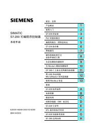
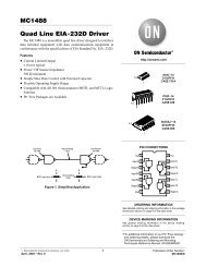
Electrical Specific<strong>at</strong>ionsFigure 2. AGTL+ Bus Topology<strong>Pentium</strong> <strong>III</strong><strong>Processor</strong>ASIC<strong>Pentium</strong> <strong>III</strong><strong>Processor</strong>2.2 Clock Control and Low Power St<strong>at</strong>es<strong>Pentium</strong> <strong>III</strong> processors allow <strong>the</strong> use of Au<strong>to</strong>HALT, S<strong>to</strong>p-Grant, Sleep, and Deep Sleep st<strong>at</strong>es <strong>to</strong>reduce power consumption by s<strong>to</strong>pping <strong>the</strong> clock <strong>to</strong> internal sections of <strong>the</strong> processor, dependingon each particular st<strong>at</strong>e. See Figure 3 <strong>for</strong> a visual represent<strong>at</strong>ion of <strong>the</strong> <strong>Pentium</strong> <strong>III</strong> processor lowpower st<strong>at</strong>es.Figure 3. S<strong>to</strong>p Clock St<strong>at</strong>e Machine2. Au<strong>to</strong> HALT Power Down St<strong>at</strong>eBCLK running.Snoops and interrupts allowed.HALT Instruction andHALT Bus Cycle Gener<strong>at</strong>edINIT#, BINIT#, INTR,SMI#, RESET# ,NMI1. Normal St<strong>at</strong>eNormal execution.STPCLK# AssertedSnoopEventOccursSnoopEventServicedSTPCLK# De-assertedand S<strong>to</strong>p-Grant St<strong>at</strong>eentered fromAu<strong>to</strong>HALTSTPCLK#AssertedSTPCLK#De-asserted4. HALT/Grant Snoop St<strong>at</strong>eBCLK running.Service snoops <strong>to</strong> caches.Snoop Event OccursSnoop Event Serviced3. S<strong>to</strong>p Grant St<strong>at</strong>eBCLK running.Snoops and interrupts allowed.SLP#AssertedSLP#De-asserted5. Sleep St<strong>at</strong>eBCLK running.No snoops or interrupts allowed.BCLKInputS<strong>to</strong>ppedBCLKInputRestarted6. Deep Sleep St<strong>at</strong>eBCLK s<strong>to</strong>pped.No snoops or interrupts allowed.PCB75714 D<strong>at</strong>asheet
Electrical Specific<strong>at</strong>ionsFor <strong>the</strong> processor <strong>to</strong> fully realize <strong>the</strong> low current consumption of <strong>the</strong> S<strong>to</strong>p-Grant, Sleep, and DeepSleep st<strong>at</strong>es, a Model Specific Register (MSR) bit must be set. For <strong>the</strong> MSR <strong>at</strong> 02Ah (Hex), bit 26must be set <strong>to</strong> a ‘1’ (this is <strong>the</strong> power on default setting) <strong>for</strong> <strong>the</strong> processor <strong>to</strong> s<strong>to</strong>p all internal clocksduring <strong>the</strong>se modes. For more in<strong>for</strong>m<strong>at</strong>ion, see <strong>the</strong> <strong>Intel</strong> Architecture Software Developer’sManual, Volume 3: System Programming Guide (Document Number 243192).Due <strong>to</strong> <strong>the</strong> inability of processors <strong>to</strong> recognize bus transactions during <strong>the</strong> Sleep and Deep Sleepst<strong>at</strong>es, 2-way MP systems are not allowed <strong>to</strong> have one processor in Sleep/Deep Sleep st<strong>at</strong>e and <strong>the</strong>o<strong>the</strong>r processor in Normal or S<strong>to</strong>p-Grant st<strong>at</strong>e simultaneously.2.2.1 Normal St<strong>at</strong>e—St<strong>at</strong>e 1This is <strong>the</strong> normal oper<strong>at</strong>ing st<strong>at</strong>e <strong>for</strong> <strong>the</strong> processor.2.2.2 Au<strong>to</strong>HALT Powerdown St<strong>at</strong>e—St<strong>at</strong>e 2Au<strong>to</strong>HALT is a low power st<strong>at</strong>e entered when <strong>the</strong> processor executes <strong>the</strong> HALT instruction. Theprocessor will transition <strong>to</strong> <strong>the</strong> Normal st<strong>at</strong>e upon <strong>the</strong> occurrence of SMI#, BINIT#, INIT#, orLINT[1:0] (NMI, INTR). RESET# will cause <strong>the</strong> processor <strong>to</strong> immedi<strong>at</strong>ely initialize itself.The return from a System Management Interrupt (SMI) handler can be <strong>to</strong> ei<strong>the</strong>r Normal Mode or<strong>the</strong> Au<strong>to</strong>HALT Power Down st<strong>at</strong>e. See <strong>the</strong> <strong>Intel</strong> Architecture Software Developer's Manual,Volume <strong>III</strong>: System Programmer's Guide (Document Number 243192) <strong>for</strong> more in<strong>for</strong>m<strong>at</strong>ion.FLUSH# will be serviced during <strong>the</strong> Au<strong>to</strong>HALT st<strong>at</strong>e, and <strong>the</strong> processor will return <strong>to</strong> <strong>the</strong>Au<strong>to</strong>HALT st<strong>at</strong>e.The system can gener<strong>at</strong>e a STPCLK# while <strong>the</strong> processor is in <strong>the</strong> Au<strong>to</strong>HALT Power Down st<strong>at</strong>e.When <strong>the</strong> system deasserts <strong>the</strong> STPCLK# interrupt, <strong>the</strong> processor will return execution <strong>to</strong> <strong>the</strong>HALT st<strong>at</strong>e.2.2.3 S<strong>to</strong>p-Grant St<strong>at</strong>e—St<strong>at</strong>e 3The S<strong>to</strong>p-Grant st<strong>at</strong>e on <strong>the</strong> processor is entered when <strong>the</strong> STPCLK# signal is asserted.Since <strong>the</strong> AGTL+ signal pins receive power from <strong>the</strong> system bus, <strong>the</strong>se pins should not be driven(allowing <strong>the</strong> level <strong>to</strong> return <strong>to</strong> VTT) <strong>for</strong> minimum power drawn by <strong>the</strong> termin<strong>at</strong>ion resis<strong>to</strong>rs in thisst<strong>at</strong>e. In addition, all o<strong>the</strong>r input pins on <strong>the</strong> system bus should be driven <strong>to</strong> <strong>the</strong> inactive st<strong>at</strong>e.BINIT# and FLUSH# will not be serviced during S<strong>to</strong>p-Grant st<strong>at</strong>e.RESET# will cause <strong>the</strong> processor <strong>to</strong> immedi<strong>at</strong>ely initialize itself, but <strong>the</strong> processor will stay inS<strong>to</strong>p-Grant st<strong>at</strong>e. A transition back <strong>to</strong> <strong>the</strong> Normal st<strong>at</strong>e will occur with <strong>the</strong> deassertion of <strong>the</strong>STPCLK# signal.A transition <strong>to</strong> <strong>the</strong> HALT/Grant Snoop st<strong>at</strong>e will occur when <strong>the</strong> processor detects a snoop on <strong>the</strong>system bus (see Section 2.2.4). A transition <strong>to</strong> <strong>the</strong> Sleep st<strong>at</strong>e (see Section 2.2.5) will occur with <strong>the</strong>assertion of <strong>the</strong> SLP# signal.While in S<strong>to</strong>p-Grant St<strong>at</strong>e, SMI#, INIT#, and LINT[1:0] will be l<strong>at</strong>ched by <strong>the</strong> processor, and onlyserviced when <strong>the</strong> processor returns <strong>to</strong> <strong>the</strong> Normal st<strong>at</strong>e. Only one occurrence of each event will berecognized and serviced upon return <strong>to</strong> <strong>the</strong> Normal st<strong>at</strong>e.D<strong>at</strong>asheet 15
Electrical Specific<strong>at</strong>ions2.2.4 HALT/Grant Snoop St<strong>at</strong>e—St<strong>at</strong>e 4The processor will respond <strong>to</strong> snoop transactions on <strong>the</strong> <strong>Pentium</strong> <strong>III</strong> processor system bus while inS<strong>to</strong>p-Grant st<strong>at</strong>e or in Au<strong>to</strong>HALT Power Down st<strong>at</strong>e. During a snoop transaction, <strong>the</strong> processorenters <strong>the</strong> HALT/Grant Snoop st<strong>at</strong>e. The processor will stay in this st<strong>at</strong>e until <strong>the</strong> snoop on <strong>the</strong><strong>Pentium</strong> <strong>III</strong> processor system bus has been serviced (whe<strong>the</strong>r by <strong>the</strong> processor or ano<strong>the</strong>r agent on<strong>the</strong> <strong>Pentium</strong> <strong>III</strong> processor system bus). After <strong>the</strong> snoop is serviced, <strong>the</strong> processor will return <strong>to</strong> <strong>the</strong>S<strong>to</strong>p-Grant st<strong>at</strong>e or Au<strong>to</strong>HALT Power Down st<strong>at</strong>e, as appropri<strong>at</strong>e.2.2.5 Sleep St<strong>at</strong>e—St<strong>at</strong>e 5The Sleep st<strong>at</strong>e is a very low power st<strong>at</strong>e in which <strong>the</strong> processor maintains its context, maintains<strong>the</strong> phase-locked loop (PLL), and has s<strong>to</strong>pped all internal clocks. The Sleep st<strong>at</strong>e can only beentered from <strong>the</strong> S<strong>to</strong>p-Grant st<strong>at</strong>e. Once in <strong>the</strong> S<strong>to</strong>p-Grant st<strong>at</strong>e, <strong>the</strong> SLP# pin can be asserted,causing <strong>the</strong> processor <strong>to</strong> enter <strong>the</strong> Sleep st<strong>at</strong>e. The SLP# pin is not recognized in <strong>the</strong> Normal orAu<strong>to</strong>HALT st<strong>at</strong>es.Snoop events th<strong>at</strong> occur while in Sleep St<strong>at</strong>e or during a transition in<strong>to</strong> or out of Sleep st<strong>at</strong>e willcause unpredictable behavior.In <strong>the</strong> Sleep st<strong>at</strong>e, <strong>the</strong> processor is incapable of responding <strong>to</strong> snoop transactions or l<strong>at</strong>chinginterrupt signals. No transitions or assertions of signals (with <strong>the</strong> exception of SLP# or RESET#)are allowed on <strong>the</strong> system bus while <strong>the</strong> processor is in Sleep st<strong>at</strong>e. Any transition on an inputsignal be<strong>for</strong>e <strong>the</strong> processor has returned <strong>to</strong> S<strong>to</strong>p-Grant st<strong>at</strong>e will result in unpredictable behavior.If RESET# is driven active while <strong>the</strong> processor is in <strong>the</strong> Sleep st<strong>at</strong>e, and held active as specified in<strong>the</strong> RESET# pin specific<strong>at</strong>ion, <strong>the</strong>n <strong>the</strong> processor will reset itself, ignoring <strong>the</strong> transition throughS<strong>to</strong>p-Grant St<strong>at</strong>e. If RESET# is driven active while <strong>the</strong> processor is in <strong>the</strong> Sleep St<strong>at</strong>e, <strong>the</strong> SLP#and STPCLK# signals should be deasserted immedi<strong>at</strong>ely after RESET# is asserted <strong>to</strong> ensure <strong>the</strong>processor correctly executes <strong>the</strong> Reset sequence.While in <strong>the</strong> Sleep st<strong>at</strong>e, <strong>the</strong> processor is capable of entering its lowest power st<strong>at</strong>e, <strong>the</strong> Deep Sleepst<strong>at</strong>e, by s<strong>to</strong>pping <strong>the</strong> BCLK input (see Section 2.2.6). Once in <strong>the</strong> Sleep or Deep Sleep st<strong>at</strong>es, <strong>the</strong>SLP# pin can be deasserted if ano<strong>the</strong>r asynchronous system bus event occurs. The SLP# pin has aminimum assertion of one BCLK period.2.2.6 Deep Sleep St<strong>at</strong>e—St<strong>at</strong>e 6The Deep Sleep st<strong>at</strong>e is <strong>the</strong> lowest power st<strong>at</strong>e <strong>the</strong> processor can enter while maintaining context.The Deep Sleep st<strong>at</strong>e is entered by s<strong>to</strong>pping <strong>the</strong> BCLK input (after <strong>the</strong> Sleep st<strong>at</strong>e was entered from<strong>the</strong> assertion of <strong>the</strong> SLP# pin). The processor is in Deep Sleep st<strong>at</strong>e immedi<strong>at</strong>ely after BCLK iss<strong>to</strong>pped. It is recommended th<strong>at</strong> <strong>the</strong> BCLK input be held low during <strong>the</strong> Deep Sleep St<strong>at</strong>e. S<strong>to</strong>ppingof <strong>the</strong> BCLK input lowers <strong>the</strong> overall current consumption <strong>to</strong> leakage levels.To re-enter <strong>the</strong> Sleep st<strong>at</strong>e, <strong>the</strong> BCLK input must be restarted. A period of 1 ms (<strong>to</strong> allow <strong>for</strong> PLLstabiliz<strong>at</strong>ion) must occur be<strong>for</strong>e <strong>the</strong> processor can be considered <strong>to</strong> be in <strong>the</strong> Sleep st<strong>at</strong>e. Once in<strong>the</strong> Sleep st<strong>at</strong>e, <strong>the</strong> SLP# pin can be deasserted <strong>to</strong> re-enter <strong>the</strong> S<strong>to</strong>p-Grant st<strong>at</strong>e.While in Deep Sleep st<strong>at</strong>e, <strong>the</strong> processor is incapable of responding <strong>to</strong> snoop transactions orl<strong>at</strong>ching interrupt signals. No transitions or assertions of signals are allowed on <strong>the</strong> system buswhile <strong>the</strong> processor is in Deep Sleep st<strong>at</strong>e. Any transition on an input signal be<strong>for</strong>e <strong>the</strong> processorhas returned <strong>to</strong> S<strong>to</strong>p-Grant st<strong>at</strong>e will result in unpredictable behavior.16 D<strong>at</strong>asheet
Electrical Specific<strong>at</strong>ions2.2.7 Clock ControlThe processor provides <strong>the</strong> clock signal <strong>to</strong> <strong>the</strong> L2 cache. During Au<strong>to</strong>HALT Power Down andS<strong>to</strong>p-Grant st<strong>at</strong>es, <strong>the</strong> processor will process a system bus snoop. The processor will not s<strong>to</strong>p <strong>the</strong>clock <strong>to</strong> <strong>the</strong> L2 cache during Au<strong>to</strong>HALT Power Down or S<strong>to</strong>p-Grant st<strong>at</strong>es. Entrance in<strong>to</strong> <strong>the</strong> Halt/Grant Snoop st<strong>at</strong>e will allow <strong>the</strong> L2 cache <strong>to</strong> be snooped, similar <strong>to</strong> <strong>the</strong> Normal st<strong>at</strong>e.When <strong>the</strong> processor is in Sleep and Deep Sleep st<strong>at</strong>es, it will not respond <strong>to</strong> interrupts or snooptransactions. During <strong>the</strong> Sleep st<strong>at</strong>e, <strong>the</strong> clock <strong>to</strong> <strong>the</strong> L2 cache is not s<strong>to</strong>pped. During <strong>the</strong> DeepSleep st<strong>at</strong>e, <strong>the</strong> clock <strong>to</strong> <strong>the</strong> L2 cache is s<strong>to</strong>pped. The clock <strong>to</strong> <strong>the</strong> L2 cache will be restarted onlyafter <strong>the</strong> internal clocking mechanism <strong>for</strong> <strong>the</strong> processor is stable (i.e., <strong>the</strong> processor has re-enteredSleep st<strong>at</strong>e).PICCLK should not be removed during <strong>the</strong> Au<strong>to</strong>HALT Power Down or S<strong>to</strong>p-Grant st<strong>at</strong>es.PICCLK can be removed during <strong>the</strong> Sleep or Deep Sleep st<strong>at</strong>es. When transitioning from <strong>the</strong> DeepSleep st<strong>at</strong>e <strong>to</strong> <strong>the</strong> Sleep st<strong>at</strong>e, PICCLK must be restarted with BCLK.2.3 Power and Ground PinsFor clean on-chip power distribution, <strong>Pentium</strong> <strong>III</strong> processors have 27 VCC (power) and 30 VSS(ground) inputs. The 27 VCC pins are fur<strong>the</strong>r divided <strong>to</strong> provide <strong>the</strong> different voltage levels <strong>to</strong> <strong>the</strong>components. VCC CORE inputs <strong>for</strong> <strong>the</strong> processor core and some L2 cache components account <strong>for</strong>19 of <strong>the</strong> VCC pins, while 4 VTT inputs (1.5 V) are used <strong>to</strong> provide an AGTL+ termin<strong>at</strong>ion voltage<strong>to</strong> <strong>the</strong> processor and 3 VCC L2 /VCC 3.3 inputs (3.3 V) are ei<strong>the</strong>r used <strong>for</strong> <strong>the</strong> off-chip L2 cacheTagRAM and BSRAMs (CPUID=067xh) or <strong>for</strong> <strong>the</strong> voltage clamp logic (CPUID=068xh). OneVCC 5 pin is provided <strong>for</strong> use by test equipment and <strong>to</strong>ols. VCC 5 , VCC L2 /VCC 3.3 , and VCC COREmust remain electrically separ<strong>at</strong>ed from each o<strong>the</strong>r. On <strong>the</strong> circuit board, all VCC CORE pins must beconnected <strong>to</strong> a voltage island and all VCC L2 /VCC 3.3 pins must be connected <strong>to</strong> a separ<strong>at</strong>e voltageisland (an island is a portion of a power plane th<strong>at</strong> has been divided, or an entire plane). Similarly,all VSS pins must be connected <strong>to</strong> a system ground plane.Note:The voltage clamp logic acts as a voltage transl<strong>at</strong>or between <strong>the</strong> processor’s 1.5 V <strong>to</strong>lerant CMOSsignals and <strong>the</strong> 2.5 V CMOS voltage on <strong>the</strong> mo<strong>the</strong>rboard. This logic is only available with<strong>Pentium</strong> <strong>III</strong> processors with CPUID=068xh.2.4 Decoupling GuidelinesDue <strong>to</strong> <strong>the</strong> large number of transis<strong>to</strong>rs and high internal clock speeds, <strong>the</strong> processor is capable ofgener<strong>at</strong>ing large average current swings between low and full power st<strong>at</strong>es. This causes voltages onpower planes <strong>to</strong> sag below <strong>the</strong>ir nominal values if bulk decoupling is not adequ<strong>at</strong>e. Care must betaken in <strong>the</strong> board design <strong>to</strong> ensure th<strong>at</strong> <strong>the</strong> voltage provided <strong>to</strong> <strong>the</strong> processor remains within <strong>the</strong>specific<strong>at</strong>ions listed in Table 8. Failure <strong>to</strong> do so can result in timing viol<strong>at</strong>ions or a reduced lifetimeof <strong>the</strong> processor.D<strong>at</strong>asheet 17
Electrical Specific<strong>at</strong>ions2.4.1 <strong>Processor</strong> VCC CORE DecouplingRegul<strong>at</strong>or solutions need <strong>to</strong> provide bulk capacitance with a low Effective Series Resistance (ESR)and keep an interconnect resistance from <strong>the</strong> regul<strong>at</strong>or (or VRM pins) <strong>to</strong> <strong>the</strong> <strong>SC242</strong> connec<strong>to</strong>r ofless than 0.3 mΩ. This can be accomplished by keeping a maximum distance of <strong>1.0</strong> inches between<strong>the</strong> regul<strong>at</strong>or output and <strong>SC242</strong> connec<strong>to</strong>r. The recommended VCC CORE interconnect is a 2.0 inchwide by <strong>1.0</strong> inch long (maximum distance between <strong>the</strong> <strong>SC242</strong> connec<strong>to</strong>r and <strong>the</strong> VRM connec<strong>to</strong>r)plane segment with a 1-ounce pl<strong>at</strong>ing. Bulk decoupling <strong>for</strong> <strong>the</strong> large current swings when <strong>the</strong> partis powering on, or entering/exiting low power st<strong>at</strong>es, is provided on <strong>the</strong> voltage regul<strong>at</strong>ion module(VRM). If using <strong>Intel</strong>’s enabled VRM solutions see developer.intel.com <strong>for</strong> <strong>the</strong> specific<strong>at</strong>ion and alist of qualified vendors. The VCC CORE input should be capable of delivering a recommendedminimum dIcc CORE /dt (defined in Table 8) while maintaining <strong>the</strong> required <strong>to</strong>lerances (also definedin Table 8).2.4.2 <strong>Processor</strong> System Bus AGTL+ DecouplingThe <strong>Pentium</strong> <strong>III</strong> processor contains high frequency decoupling capacitance on <strong>the</strong> processorsubstr<strong>at</strong>e; bulk decoupling must be provided <strong>for</strong> by <strong>the</strong> system baseboard <strong>for</strong> proper AGTL+ busoper<strong>at</strong>ion. See AP-906, 100 <strong>MHz</strong> AGTL+ Layout Guidelines <strong>for</strong> <strong>the</strong> <strong>Intel</strong> ® <strong>Pentium</strong> ® <strong>III</strong> <strong>Processor</strong>and <strong>Intel</strong> ® 440BX AGPset (Document Number 2<strong>450</strong>86) or <strong>the</strong> appropri<strong>at</strong>e pl<strong>at</strong><strong>for</strong>m design guide,AP-907, <strong>Pentium</strong> ® <strong>III</strong> <strong>Processor</strong> Power Distribution Guidelines (Document Number 2<strong>450</strong>85), and<strong>the</strong> GTL+ buffer specific<strong>at</strong>ion in <strong>the</strong> <strong>Pentium</strong> ® II <strong>Processor</strong> Developer's Manual (DocumentNumber 243502) <strong>for</strong> more in<strong>for</strong>m<strong>at</strong>ion.2.5 <strong>Processor</strong> System Bus Clock and <strong>Processor</strong> ClockingThe BCLK input directly controls <strong>the</strong> oper<strong>at</strong>ing speed of <strong>the</strong> <strong>Pentium</strong> <strong>III</strong> processor system businterface. All <strong>Pentium</strong> <strong>III</strong> processor system bus timing parameters are specified with respect <strong>to</strong> <strong>the</strong>rising edge of <strong>the</strong> BCLK input. See <strong>the</strong> P6 Family of <strong>Processor</strong>s Hardware Developer's Manual(Document Number 244001) <strong>for</strong> fur<strong>the</strong>r details.2.6 Voltage Identific<strong>at</strong>ionThere are five voltage identific<strong>at</strong>ion pins on <strong>the</strong> <strong>SC242</strong> connec<strong>to</strong>r. These pins can be used <strong>to</strong>support au<strong>to</strong>m<strong>at</strong>ic selection of power supply voltages. These pins are not signals, but are ei<strong>the</strong>r anopen circuit or a short circuit <strong>to</strong> VSS on <strong>the</strong> processor. The combin<strong>at</strong>ion of opens and shorts defines<strong>the</strong> voltage required by <strong>the</strong> processor core. The VID pins are needed <strong>to</strong> cleanly support voltagespecific<strong>at</strong>ion vari<strong>at</strong>ions on current and future <strong>Pentium</strong> <strong>III</strong> processors. VID[4:0] are defined inTable 3. A ‘1’ in this table refers <strong>to</strong> an open pin and a ‘0’ refers <strong>to</strong> a short <strong>to</strong> ground. The powersupply must supply <strong>the</strong> voltage th<strong>at</strong> is requested or disable itself.To ensure a system is ready <strong>for</strong> current and future <strong>Pentium</strong> <strong>III</strong> processors, <strong>the</strong> range of values inbold in Table 3 should be supported. A smaller range will risk <strong>the</strong> ability of <strong>the</strong> system <strong>to</strong> migr<strong>at</strong>e<strong>to</strong> a higher per<strong>for</strong>mance <strong>Pentium</strong> <strong>III</strong> processor and/or maintain comp<strong>at</strong>ibility with current<strong>Pentium</strong> <strong>III</strong> processors.18 D<strong>at</strong>asheet
Electrical Specific<strong>at</strong>ionsTable 3.Voltage Identific<strong>at</strong>ion Definition<strong>Processor</strong> PinsNotes 1,2VID4 VID3 VID2 VID1 VID0 Vcc CORE0 1 1 1 1 1.300 1 1 1 0 1.350 1 1 0 1 1.400 1 1 0 0 1.<strong>450</strong> 1 0 1 1 1.500 1 0 1 0 1.550 1 0 0 1 1.60 30 1 0 0 0 1.65 30 0 1 1 1 1.70 30 0 1 1 0 1.75 30 0 1 0 1 1.80 30 0 1 0 0 1.85 30 0 0 1 1 1.90 30 0 0 1 0 1.95 30 0 0 0 1 2.00 30 0 0 0 0 2.05 31 1 1 1 1 No Core1 1 1 1 0 2.11 1 1 0 1 2.21 1 1 0 0 2.31 1 0 1 1 2.41 1 0 1 0 2.51 1 0 0 1 2.61 1 0 0 0 2.71 0 1 1 1 2.81 0 1 1 0 2.91 0 1 0 1 3.01 0 1 0 0 3.11 0 0 1 1 3.21 0 0 1 0 3.31 0 0 0 1 3.41 0 0 0 0 3.5NOTES:1. 0 = <strong>Processor</strong> pin connected <strong>to</strong> VSS.2. 1 = Open on processor; may be pulled up <strong>to</strong> TTL V IH on baseboard.3. To ensure a system is ready <strong>for</strong> <strong>the</strong> <strong>Pentium</strong> <strong>III</strong> processor, <strong>the</strong> values in BOLD in Table 3 should besupported.Note th<strong>at</strong> <strong>the</strong> ‘11111’ (all opens) ID can be used <strong>to</strong> detect <strong>the</strong> absence of a processor core in a givenconnec<strong>to</strong>r as long as <strong>the</strong> power supply used does not affect <strong>the</strong>se lines. Detection logic and pull-upsshould not affect VID inputs <strong>at</strong> <strong>the</strong> power source (see Section 7.0).The VID pins should be pulled up <strong>to</strong> a TTL-comp<strong>at</strong>ible level with external resis<strong>to</strong>rs <strong>to</strong> <strong>the</strong> powersource of <strong>the</strong> regul<strong>at</strong>or only if required by <strong>the</strong> regul<strong>at</strong>or or external logic moni<strong>to</strong>ring <strong>the</strong> VID[4:0]signals. The power source chosen must be guaranteed <strong>to</strong> be stable whenever <strong>the</strong> supply <strong>to</strong> <strong>the</strong>D<strong>at</strong>asheet 19
Electrical Specific<strong>at</strong>ionsvoltage regul<strong>at</strong>or is stable. This will prevent <strong>the</strong> possibility of <strong>the</strong> processor supply going above <strong>the</strong>specified VCC CORE in <strong>the</strong> event of a failure in <strong>the</strong> supply <strong>for</strong> <strong>the</strong> VID lines. In <strong>the</strong> case of a DC-<strong>to</strong>-DC converter, this can be accomplished by using <strong>the</strong> input voltage <strong>to</strong> <strong>the</strong> converter <strong>for</strong> <strong>the</strong> VID linepull-ups. A resis<strong>to</strong>r of gre<strong>at</strong>er than or equal <strong>to</strong> 10 kΩ may be used <strong>to</strong> connect <strong>the</strong> VID signals <strong>to</strong> <strong>the</strong>converter input.2.7 <strong>Processor</strong> System Bus Unused PinsAll RESERVED pins must remain unconnected. Connection of <strong>the</strong>se pins <strong>to</strong> VCC CORE , VCC L2 /VCC 3.3 , VSS, or <strong>to</strong> any o<strong>the</strong>r signal (including each o<strong>the</strong>r) can result in component malfunction orincomp<strong>at</strong>ibility with future <strong>Pentium</strong> <strong>III</strong> processors. See Section 5.5 <strong>for</strong> a pin listing of <strong>the</strong> processorand <strong>the</strong> loc<strong>at</strong>ion of each RESERVED pin.All TESTHI pins must be connected <strong>to</strong> 2.5 V via 1 kΩ –10 kΩ pull-up resis<strong>to</strong>r.PICCLK must be driven with a valid clock input and <strong>the</strong> PICD[1:0] lines must be pulled-up <strong>to</strong>2.5 V even when <strong>the</strong> APIC will not be used. A separ<strong>at</strong>e pull-up resis<strong>to</strong>r must be provided <strong>for</strong> eachAPIC d<strong>at</strong>a line.For reliable oper<strong>at</strong>ion, always connect unused inputs or bidirectional signals <strong>to</strong> an appropri<strong>at</strong>esignal level. Unused AGTL+ inputs should be left as no connects; AGTL+ termin<strong>at</strong>ion is providedon <strong>the</strong> processor. Unused active low CMOS inputs should be connected through a resis<strong>to</strong>r <strong>to</strong> 2.5 V.Unused active high inputs should be connected through a resis<strong>to</strong>r <strong>to</strong> ground (VSS). Unused outputscan be left unconnected. A resis<strong>to</strong>r must be used when tying bidirectional signals <strong>to</strong> power orground. When tying any signal <strong>to</strong> power or ground, a resis<strong>to</strong>r will also allow <strong>for</strong> system testability.For unused pins, it is suggested th<strong>at</strong> ~10 kΩ resis<strong>to</strong>rs be used <strong>for</strong> pull-ups (except <strong>for</strong> PICD[1:0]discussed above), and ~1 kΩ resis<strong>to</strong>rs be used as pull-downs.2.8 <strong>Processor</strong> System Bus Signal GroupsIn order <strong>to</strong> simplify <strong>the</strong> following discussion, <strong>the</strong> <strong>Pentium</strong> <strong>III</strong> processor system bus signals havebeen combined in<strong>to</strong> groups by buffer type. All <strong>Pentium</strong> <strong>III</strong> processor system bus outputs are opendrain and require a high-level source provided externally by <strong>the</strong> termin<strong>at</strong>ion or pull-up resis<strong>to</strong>r.However, <strong>the</strong> <strong>Pentium</strong> <strong>III</strong> processor includes on-cartridge (CPUID=067xh) or on-die(CPUID=068xh) termin<strong>at</strong>ion.AGTL+ input signals have differential input buffers, which use V REF as a reference signal. AGTL+output signals require termin<strong>at</strong>ion <strong>to</strong> 1.5 V. In this document, <strong>the</strong> term “AGTL+ Input” refers <strong>to</strong> <strong>the</strong>AGTL+ input group as well as <strong>the</strong> AGTL+ I/O group when receiving. Similarly, “AGTL+ Output”refers <strong>to</strong> <strong>the</strong> AGTL+ output group as well as <strong>the</strong> AGTL+ I/O group when driving.EMI pins may be connected <strong>to</strong> baseboard ground and/or <strong>to</strong> chassis ground through zero ohm (0 Ω)resis<strong>to</strong>rs. The 0 Ω resis<strong>to</strong>rs should be placed in close proximity <strong>to</strong> <strong>the</strong> <strong>SC242</strong> connec<strong>to</strong>r. The p<strong>at</strong>h <strong>to</strong>chassis ground should be short in length and have a low impedance.The CMOS, Clock, APIC, and TAP inputs can each be driven from ground <strong>to</strong> 2.5 V. The CMOS,APIC, and TAP outputs are open drain and should be pulled high <strong>to</strong> 2.5 V. This ensures not onlycorrect oper<strong>at</strong>ion <strong>for</strong> current <strong>Pentium</strong> <strong>III</strong> processors, but comp<strong>at</strong>ibility with future <strong>Pentium</strong> <strong>III</strong>processors as well.The groups and <strong>the</strong> signals contained within each group are shown in Table 4. Refer <strong>to</strong> Section 7.0<strong>for</strong> a description of <strong>the</strong>se signals.20 D<strong>at</strong>asheet
Electrical Specific<strong>at</strong>ionsTable 4.System Bus Signal GroupsGroup NameSignalsAGTL+ InputAGTL+ OutputBPRI#, BR1#, DEFER#, RESET#, RS[2:0]#, RSP#, TRDY#PRDY#AGTL+ I/OA[35:3]#, ADS#, AERR#, AP[1:0]#, BERR#, BINIT#, BNR#, BP[3:2]#, BPM[1:0]#,BR0# 1 , D[63:0]#, DBSY#, DEP[7:0]#, DRDY#, HIT#, HITM#, LOCK#, REQ[4:0]#, RP#CMOS Input 5 A20M#, FLUSH#, IGNNE#, INIT#, LINT0/INTR, LINT1/NMI, PREQ#, PWRGOOD 2 ,SMI#, SLP# 3 , STPCLK#CMOS Output 5 FERR#, IERR#, THERMTRIP# 4System Bus Clock BCLKAPIC Clock PICCLKAPIC I/O 5PICD[1:0]TAP Input 5 TCK, TDI, TMS, TRST#TAP Output 5 TDOPower/O<strong>the</strong>r 6VCC CORE , VCC L2 /VCC 3.3 , VCC 5 , VID[4:0], VTT, VSS, SLOTOCC#, THERMDP, THERMDN,BSEL[1:0], EMI, TESTHI, ReservedNOTES:1. The BR0# pin is <strong>the</strong> only BREQ# signal th<strong>at</strong> is bidirectional. The internal BREQ# signals are mapped on<strong>to</strong>BR# pins after <strong>the</strong> agent ID is determined. See Section 7.0 <strong>for</strong> more in<strong>for</strong>m<strong>at</strong>ion.2. See Section 7.0 <strong>for</strong> in<strong>for</strong>m<strong>at</strong>ion on <strong>the</strong> PWRGOOD signal.3. See Section 7.0 <strong>for</strong> in<strong>for</strong>m<strong>at</strong>ion on <strong>the</strong> SLP# signal.4. See Section 7.0 <strong>for</strong> in<strong>for</strong>m<strong>at</strong>ion on <strong>the</strong> THERMTRIP# signal.5. These signals are specified <strong>for</strong> 2.5 V oper<strong>at</strong>ion.6. VCC CORE is <strong>the</strong> power supply <strong>for</strong> <strong>the</strong> processor core.VCC L2 /VCC 3.3 is described in Section 2.3.VID[4:0] is described in Section 2.6.VTT is used <strong>to</strong> termin<strong>at</strong>e <strong>the</strong> system bus and gener<strong>at</strong>e V REF on <strong>the</strong> processor substr<strong>at</strong>e.VSS is system ground.TESTHI should be connected <strong>to</strong> 2.5 V with a 1 kΩ –10 kΩ resis<strong>to</strong>r.VCC 5 is not connected <strong>to</strong> <strong>the</strong> <strong>Pentium</strong> <strong>III</strong> processor core. This supply is used <strong>for</strong> <strong>the</strong> test equipment and <strong>to</strong>ols.SLOTOCC# is described in Section 7.0.BSEL[1:0] is described in Section 2.8.2 and Section 7.0.EMI pins are described in Section 7.0.THERMDP, THERMDN are described in Section 7.0.2.8.1 Asynchronous vs. Synchronous <strong>for</strong> System Bus SignalsAll AGTL+ signals are synchronous <strong>to</strong> BCLK. All of <strong>the</strong> CMOS, Clock, APIC, and TAP signalscan be applied asynchronously <strong>to</strong> BCLK.All APIC signals are synchronous <strong>to</strong> PICCLK. All TAP signals are synchronous <strong>to</strong> TCK.D<strong>at</strong>asheet 21
Electrical Specific<strong>at</strong>ions2.8.2 System Bus Frequency Select Signal (BSEL0)The BSEL[1:0] signals (BSEL0 is also known as 100/66#) are used <strong>to</strong> select <strong>the</strong> system busfrequency <strong>for</strong> <strong>the</strong> <strong>Pentium</strong> <strong>III</strong> processor(s). Table 5 defines <strong>the</strong> possible combin<strong>at</strong>ions of <strong>the</strong> signalsand <strong>the</strong> frequency associ<strong>at</strong>ed with each combin<strong>at</strong>ion. The frequency is determined by <strong>the</strong>processor(s), and frequency syn<strong>the</strong>sizer. All system bus agents must oper<strong>at</strong>e <strong>at</strong> <strong>the</strong> same core andsystem bus frequency in a 2-way MP <strong>Pentium</strong> <strong>III</strong> processor configur<strong>at</strong>ion. In a 2-way MP systemdesign, <strong>the</strong> BSEL[1:0] signals must be connected <strong>to</strong> <strong>the</strong> BSEL[1:0] pins of both processors. The<strong>Pentium</strong> <strong>III</strong> processor oper<strong>at</strong>es <strong>at</strong> ei<strong>the</strong>r a 100 <strong>MHz</strong> or 133 <strong>MHz</strong> system bus frequency, but notboth. 66 <strong>MHz</strong> system bus oper<strong>at</strong>ion is not supported.For systems th<strong>at</strong> support only a 100 <strong>MHz</strong> system bus clock, resis<strong>to</strong>rs on <strong>the</strong> processor cartridgewill tie <strong>the</strong> BSEL1 signal <strong>to</strong> ground (as shown in Figure 4). This signal can ei<strong>the</strong>r be left as a noconnect or tied <strong>to</strong> ground as shown below. The BSEL0 should be pulled up <strong>to</strong> 3.3 V with a 220 Ωresis<strong>to</strong>r, and provided as a frequency driver <strong>to</strong> <strong>the</strong> clock driver/syn<strong>the</strong>sizer.On baseboards which support oper<strong>at</strong>ion <strong>at</strong> ei<strong>the</strong>r 100 or 133 <strong>MHz</strong>, <strong>the</strong> BSEL[1:0] signals should bepulled up <strong>to</strong> 3.3 V with a 220 Ω resis<strong>to</strong>r (as shown in Figure 5 and Figure 6) and BSEL1 isprovided as a frequency selection signal <strong>to</strong> <strong>the</strong> clock driver/syn<strong>the</strong>sizer. The BSEL0 signal can alsobe incorpor<strong>at</strong>ed in<strong>to</strong> system shutdown logic on <strong>the</strong> baseboard (thus <strong>for</strong>cing <strong>the</strong> system <strong>to</strong> shutdownas long as <strong>the</strong> BSEL0 signal is low). Figure 4 shows this routing example with a 100 <strong>MHz</strong><strong>Pentium</strong> <strong>III</strong> processor. Figure 5 shows <strong>the</strong> same routing example with a 133 <strong>MHz</strong> <strong>Pentium</strong> <strong>III</strong>processor.Table 5.Frequency Select Truth Table <strong>for</strong> BSEL[1:0]BSEL1 BSEL0 Frequency0 0 66 <strong>MHz</strong> (unsupported)0 1 100 <strong>MHz</strong>1 0 Reserved1 1 133 <strong>MHz</strong>Figure 4. BSEL[1:0] Example <strong>for</strong> a 100 <strong>MHz</strong> System Design (100 <strong>MHz</strong> <strong>Processor</strong> Installed)<strong>Intel</strong> ® <strong>Pentium</strong> ® <strong>III</strong> <strong>Processor</strong>220 Ω3.3VCK100100/66#GND<strong>SC242</strong>0 Ω 0 ΩBSEL1<strong>Processor</strong>CoreGNDBSEL01 ΚΩ 3.3 ΚΩGND22 D<strong>at</strong>asheet
Electrical Specific<strong>at</strong>ionsFigure 5. BSEL[1:0] Example <strong>for</strong> a 100/133 <strong>MHz</strong> Capable System(100 <strong>MHz</strong> <strong>Processor</strong> Installed)3.3V220 ΩCK133220 Ω3.3VSystemShutdownLogic133/100#BSEL1BSEL0<strong>SC242</strong><strong>Intel</strong> ® <strong>Pentium</strong> ® <strong>III</strong> <strong>Processor</strong>0 Ω 0 Ω<strong>Processor</strong>Core1 ΚΩ 3.3 ΚΩGNDGNDFigure 6. BSEL[1:0] Example <strong>for</strong> a 100/133 <strong>MHz</strong> Capable System(133 <strong>MHz</strong> <strong>Processor</strong> Installed)3.3V220 ΩCK133220 Ω3.3VSystemShutdownLogic133/100#BSEL1BSEL0<strong>SC242</strong><strong>Intel</strong> ® <strong>Pentium</strong> ® <strong>III</strong> <strong>Processor</strong>1 ΚΩ 3.3 ΚΩ<strong>Processor</strong>Core1 ΚΩ 3.3 ΚΩGNDGND2.9 Test Access Port (TAP) ConnectionDue <strong>to</strong> <strong>the</strong> voltage levels supported by o<strong>the</strong>r components in <strong>the</strong> Test Access Port (TAP) logic, it isrecommended th<strong>at</strong> <strong>the</strong> <strong>Pentium</strong> <strong>III</strong> processor be first in <strong>the</strong> TAP chain and followed by any o<strong>the</strong>rcomponents within <strong>the</strong> system. A transl<strong>at</strong>ion buffer should be used <strong>to</strong> connect <strong>to</strong> <strong>the</strong> rest of <strong>the</strong>chain unless one of <strong>the</strong> o<strong>the</strong>r components is capable of accepting a 2.5 V input. Similarconsider<strong>at</strong>ions must be made <strong>for</strong> TCK, TMS, and TRST#. Two copies of each signal may berequired with each driving a different voltage level.The Debug Port should be placed <strong>at</strong> <strong>the</strong> start and end of <strong>the</strong> TAP chain with <strong>the</strong> TDI of <strong>the</strong> firstcomponent coming from <strong>the</strong> Debug Port and <strong>the</strong> TDO from <strong>the</strong> last component going <strong>to</strong> <strong>the</strong> DebugPort. In a 2-way MP system, be cautious when including an empty <strong>SC242</strong> connec<strong>to</strong>r in <strong>the</strong> scanchain. All connec<strong>to</strong>rs in <strong>the</strong> scan chain must have a processor installed <strong>to</strong> complete <strong>the</strong> chain or <strong>the</strong>system must support a method <strong>to</strong> bypass <strong>the</strong> empty connec<strong>to</strong>rs; <strong>SC242</strong> termin<strong>at</strong>or substr<strong>at</strong>es shouldnot connect TDI <strong>to</strong> TDO in order <strong>to</strong> avoid placing <strong>the</strong> TDO pull-up resis<strong>to</strong>rs in parallel. See <strong>SC242</strong>Termin<strong>at</strong>or Card Design Guidelines (Document Number 243409) <strong>for</strong> more details.D<strong>at</strong>asheet 23
Electrical Specific<strong>at</strong>ions2.10 Maximum R<strong>at</strong>ingsTable 6 contains <strong>Pentium</strong> <strong>III</strong> processor stress r<strong>at</strong>ings only. Functional oper<strong>at</strong>ion <strong>at</strong> <strong>the</strong> absolutemaximum and minimum is not implied nor guaranteed. The processor should not receive a clockwhile subjected <strong>to</strong> <strong>the</strong>se conditions. Functional oper<strong>at</strong>ing conditions are given in <strong>the</strong> AC and DCtables in Section 2.11 and Section 2.13. Extended exposure <strong>to</strong> <strong>the</strong> maximum r<strong>at</strong>ings may affectdevice reliability. Fur<strong>the</strong>rmore, although <strong>the</strong> processor contains protective circuitry <strong>to</strong> resistdamage from st<strong>at</strong>ic electric discharge, one should always take precautions <strong>to</strong> avoid high st<strong>at</strong>icvoltages or electric fields.Table 6.Absolute Maximum R<strong>at</strong>ings (CPUID=067xh)Symbol Parameter Min Max Unit NotesT STORAGE <strong>Processor</strong> s<strong>to</strong>rage temper<strong>at</strong>ure –40 85 °CVCC (All)Vin AGTLVin CMOSAny processor supply voltage with respect<strong>to</strong> VSSAGTL+ buffer DC input voltage withrespect <strong>to</strong> VSSCMOS buffer DC input voltage withrespect <strong>to</strong> VSSNOTES:1. Oper<strong>at</strong>ing voltage is <strong>the</strong> voltage <strong>to</strong> which <strong>the</strong> component is designed <strong>to</strong> oper<strong>at</strong>e. See Table 8.2. This r<strong>at</strong>ing applies <strong>to</strong> <strong>the</strong> VCC CORE , VCC L2 /VCC 3.3 , VCC 5 , and any input (except as noted below) <strong>to</strong> <strong>the</strong>processor.3. Parameter applies <strong>to</strong> CMOS, APIC, and TAP bus signal groups only.4. The mechanical integrity of <strong>the</strong> l<strong>at</strong>ch arms is specified <strong>to</strong> last a maximum of 50 cycles.5. The electrical and mechanical integrity of <strong>the</strong> processor edge fingers are specified <strong>to</strong> last <strong>for</strong> 50 insertion/extraction cycles.6. While insertion/extraction cycling above 50 insertions will cause an increase in <strong>the</strong> contact resistance (above0.1 Ω) and a degrad<strong>at</strong>ion in <strong>the</strong> m<strong>at</strong>erial integrity of <strong>the</strong> edge finger gold pl<strong>at</strong>ing, it is possible <strong>to</strong> haveprocessor functionality above <strong>the</strong> specified limit. The actual number of insertions be<strong>for</strong>e processor failure willvary based upon system configur<strong>at</strong>ion and environmental conditions.7. This specific<strong>at</strong>ion only applies <strong>to</strong> S.E.C.C. packaged processors.–0.5Oper<strong>at</strong>ingvoltage + <strong>1.0</strong>–0.3 VCC CORE + 0.7 VV 1, 2–0.3 3.3 V 3IVID Max VID pin current 5 mAISLOTOCC Max SLOTOCC# pin current 5 mAMech MaxL<strong>at</strong>ch ArmsMechanical integrity of l<strong>at</strong>ch arms 50 Cycles 4, 7Mech MaxEdge FingersMechanical integrity of processor edgefingers50Insertions/Extractions5, 624 D<strong>at</strong>asheet
Electrical Specific<strong>at</strong>ionsTable 7.Absolute Maximum R<strong>at</strong>ings (CPUID=068xh)Symbol Parameter Min Max Unit NotesT STORAGE <strong>Processor</strong> s<strong>to</strong>rage temper<strong>at</strong>ure –40 85 °CVCC CORE andVTT<strong>Processor</strong> core voltage and Termin<strong>at</strong>ionsupply voltage with respect <strong>to</strong> VSS-0.5 2.1 VVCC L2 /VCC 3.3 VCC 3.3 with respect <strong>to</strong> VSS –0.5 5.0 V 1Vin 1.5 1.5 V buffer input voltage VTT – 2.3 VSS + 2.3 V 2, 3, 5Vin 2.5 2.5 V buffer input voltage –0.7 3.3 V 4IVID Max VID pin current 5 mAISLOTOCC Max SLOTOCC# pin current 5 mAMech MaxEdge FingersMechanical integrity of processor edgefingersNOTES:1. Oper<strong>at</strong>ing voltage is <strong>the</strong> voltage <strong>to</strong> which <strong>the</strong> component is designed <strong>to</strong> oper<strong>at</strong>e. See Table 7.2. Input voltage can never be above VSS + 2.3 V.3. Input voltage can never be below VTT – 2.3 V.4. Parameter applies <strong>to</strong> <strong>the</strong> 2.5 V processor core signals (BCLK, PICCLK, and PWRGOOD).5. Parameter applies <strong>to</strong> <strong>the</strong> 1.5 V processor core signals (all signals except BCLK, PICCLK, and PWRGOOD).6. The electrical and mechanical integrity of <strong>the</strong> processor edge fingers are specified <strong>to</strong> last <strong>for</strong> 50 insertion/extraction cycles.7. While insertion/extraction cycling above 50 insertions will cause an increase in <strong>the</strong> contact resistance (above0.1 Ω) and a degrad<strong>at</strong>ion in <strong>the</strong> m<strong>at</strong>erial integrity of <strong>the</strong> edge finger gold pl<strong>at</strong>ing, it is possible <strong>to</strong> haveprocessor functionality above <strong>the</strong> specified limit. The actual number of insertions be<strong>for</strong>e processor failure willvary based upon system configur<strong>at</strong>ion and environmental conditions.50Insertions/Extractions6, 72.11 <strong>Processor</strong> DC Specific<strong>at</strong>ionsThe processor DC specific<strong>at</strong>ions in this section are defined <strong>at</strong> <strong>the</strong> <strong>Pentium</strong> <strong>III</strong> processor core pins,edge fingers, and <strong>at</strong> <strong>the</strong> <strong>SC242</strong> connec<strong>to</strong>r pins. See Section 7.0 <strong>for</strong> <strong>the</strong> processor edge finger signaldefinitions and Section 5.0 <strong>for</strong> <strong>the</strong> core pin loc<strong>at</strong>ions and <strong>the</strong> signal listing.Most of <strong>the</strong> signals on <strong>the</strong> <strong>Pentium</strong> <strong>III</strong> processor system bus are in <strong>the</strong> AGTL+ signal group. Thesesignals are specified <strong>to</strong> be termin<strong>at</strong>ed <strong>to</strong> 1.5 V. The DC specific<strong>at</strong>ions <strong>for</strong> <strong>the</strong>se signals are listed inTable 9.To allow connection with o<strong>the</strong>r devices, <strong>the</strong> Clock, CMOS, APIC, and TAP signals are designed <strong>to</strong>interface <strong>at</strong> non-AGTL+ levels. The DC specific<strong>at</strong>ions <strong>for</strong> <strong>the</strong>se pins are listed in Table 10.Table 8 through Table 11 list <strong>the</strong> DC specific<strong>at</strong>ions <strong>for</strong> <strong>Pentium</strong> <strong>III</strong> processors. Specific<strong>at</strong>ions arevalid only while meeting specific<strong>at</strong>ions <strong>for</strong> case temper<strong>at</strong>ure, clock frequency, and input voltages.Care should be taken <strong>to</strong> read all notes associ<strong>at</strong>ed with each parameter.D<strong>at</strong>asheet 25
Electrical Specific<strong>at</strong>ionsTable 8. Voltage and Current Specific<strong>at</strong>ions (Sheet 1 of 4)SymbolVcc COREParameterVcc <strong>for</strong> <strong>Processor</strong> Core<strong>Processor</strong>Min Typ Max Unit Notes 1Core Freq CPUID<strong>450</strong> <strong>MHz</strong>0672h 2.002,3,4,50673h 2.00 2,3,4,5500 <strong>MHz</strong>0672h 2.00 2,3,4,50673h 2.00 2,3,4,5533 <strong>MHz</strong>0672h 2.00 2,3,4,50673h 2.00 2,3,4,50681h 1.65 2,3,4,5533EB <strong>MHz</strong> 0683h 1.65 2,3,4,50686h 1.70 2,3,4,5550 <strong>MHz</strong>0672h 2.00 2,3,4,50673h 2.00 2,3,4,50681h 1.65 2,3,4,5550E <strong>MHz</strong> 0683h 1.65 2,3,4,50686h 1.70 2,3,4,5600 <strong>MHz</strong>0672h 2.05 2,3,4,50673h 2.05 2,3,4,5600B <strong>MHz</strong>0672h 2.05 2,3,4,50673h 2.05 2,3,4,50681h 1.65 2,3,4,5600E <strong>MHz</strong> 0683h 1.65 2,3,4,50686h 1.70 2,3,4,5V0681h 1.65 2,3,4,5600EB <strong>MHz</strong> 0683h 1.65 2,3,4,50686h 1.70 2,3,4,50681h 1.65 2,3,4,5650 <strong>MHz</strong> 0683h 1.65 2,3,4,50686h 1.70 2,3,4,50681h 1.65 2,3,4,5667 <strong>MHz</strong> 0683h 1.65 2,3,4,50686h 1.70 2,3,4,50681h 1.65 2,3,4,5700 <strong>MHz</strong> 0683h 1.65 2,3,4,50686h 1.70 2,3,4,50681h 1.65 2,3,4,5733 <strong>MHz</strong> 0683h 1.65 2,3,4,50686h 1.70 2,3,4,50681h 1.65 2,3,4,5750 <strong>MHz</strong> 0683h 1.65 2,3,4,50686h 1.70 2,3,4,50681h 1.65 2,3,4,5800 <strong>MHz</strong> 0683h 1.65 2,3,4,50686h 1.70 2,3,4,526 D<strong>at</strong>asheet
Electrical Specific<strong>at</strong>ionsTable 8. Voltage and Current Specific<strong>at</strong>ions (Sheet 2 of 4)Vcc COREVCC L2 /VCC 3.3VTTSymbolBaseboardTolerance,St<strong>at</strong>icBaseboardTolerance,TransientVCC CORETolerance,St<strong>at</strong>icVCC CORETolerance,TransientParameterVcc <strong>for</strong> <strong>Processor</strong> CoreVCC <strong>for</strong> second levelcache or voltage clamplogicAGTL+ bus termin<strong>at</strong>ionvoltage<strong>Processor</strong> core voltagest<strong>at</strong>ic <strong>to</strong>lerance level <strong>at</strong><strong>SC242</strong> pins<strong>Processor</strong> core voltagetransient <strong>to</strong>lerance level <strong>at</strong><strong>SC242</strong> pins<strong>Processor</strong> core voltagest<strong>at</strong>ic <strong>to</strong>lerance level <strong>at</strong>edge fingers<strong>Processor</strong> core voltagetransient <strong>to</strong>lerance level <strong>at</strong>edge fingers<strong>Processor</strong>Core Freq800EB <strong>MHz</strong>850 <strong>MHz</strong>866 <strong>MHz</strong>933 <strong>MHz</strong><strong>1.0</strong> <strong>GHz</strong><strong>1.0</strong>B <strong>GHz</strong>CPUIDMin Typ Max Unit Notes 10681h 1.652,3,4,50683h 1.65 2,3,4,50686h 1.70 2,3,4,50681h 1.65 2,3,4,50683h 1.65 2,3,4,50686h 1.70 2,3,4,50681h 1.65 2,3,4,50683h 1.65 V 2,3,4,50686h 1.70 2,3,4,50683h 1.70 2,3,4,50686h 1.70 2,3,4,50683h 1.70 2,3,4,50686h 1.70 2,3,4,50683h 1.70 2,3,4,50686h 1.70 2,3,4,53.135 3.3 3.465 V 3.3 V ±5% 91.365 1.50 1.635 V 1.5 ±9% 6–0.070–0.080–0.050–0.055–0.140–0.080–0.050–0.055–0.085–0.110–0.065–0.075–0.170–0.110–0.065–0.0750.0700.0400.0400.0400.1400.0500.0500.0500.0850.0400.0400.0400.1700.0800.0800.080VVVV2, 7, 182, 7, 192, 7, 212, 72, 7, 182, 7, 192, 7, 212, 72, 8, 182, 8, 192, 8, 212, 82, 8, 182, 8, 192, 8, 212, 8D<strong>at</strong>asheet 27
Electrical Specific<strong>at</strong>ionsTable 8. Voltage and Current Specific<strong>at</strong>ions (Sheet 3 of 4)SymbolICC COREICC L2IVTTISG ntISG ntL2ParameterICC <strong>for</strong> processor coreICC <strong>for</strong> second level cacheTermin<strong>at</strong>ion voltagesupply currentICC S<strong>to</strong>p-Grant <strong>for</strong>processor coreICC S<strong>to</strong>p-Grant <strong>for</strong> secondlevel cache<strong>Processor</strong>Core Freq<strong>450</strong> <strong>MHz</strong>500 <strong>MHz</strong>533B <strong>MHz</strong>533EB <strong>MHz</strong>550 <strong>MHz</strong>550E <strong>MHz</strong>600 <strong>MHz</strong>600B <strong>MHz</strong>600E <strong>MHz</strong>600EB <strong>MHz</strong>650 <strong>MHz</strong>667 <strong>MHz</strong>700 <strong>MHz</strong>733 <strong>MHz</strong>750 <strong>MHz</strong>800 <strong>MHz</strong>800EB <strong>MHz</strong>850 <strong>MHz</strong>866 <strong>MHz</strong>933 <strong>MHz</strong><strong>1.0</strong> <strong>GHz</strong><strong>1.0</strong>B <strong>GHz</strong><strong>450</strong> <strong>MHz</strong>500 <strong>MHz</strong>533B <strong>MHz</strong>550 <strong>MHz</strong>600 <strong>MHz</strong>600B <strong>MHz</strong>ALL14.516.116.710.617.01<strong>1.0</strong>17.817.813.013.013.013.314.014.615.016.016.016.216.317.719.419.4<strong>1.0</strong>81.211.291.331.451.45ALL 2.7 A 12<strong>450</strong> <strong>MHz</strong>500 <strong>MHz</strong>533B <strong>MHz</strong>533EB <strong>MHz</strong>550 <strong>MHz</strong>550E <strong>MHz</strong>600 <strong>MHz</strong>600B <strong>MHz</strong>600E <strong>MHz</strong>600EB <strong>MHz</strong>650 <strong>MHz</strong>667 <strong>MHz</strong>700 <strong>MHz</strong>733 <strong>MHz</strong>750 <strong>MHz</strong>800 <strong>MHz</strong>800EB <strong>MHz</strong>850 <strong>MHz</strong>866 <strong>MHz</strong>933 <strong>MHz</strong><strong>1.0</strong> <strong>GHz</strong><strong>1.0</strong>B <strong>GHz</strong>CPUIDALLMin Typ Max Unit Notes 11.201.401.492.501.542.501.681.682.502.502.502.502.502.502.502.502.502.502.502.502.502.50AAA2, 3, 10, 112, 3, 10, 112, 3, 10, 112, 3, 202, 3, 10, 112, 3, 202, 3, 10, 112, 3, 10, 112, 3, 202, 3, 202, 3, 202, 3, 202, 3, 202, 3, 202, 3, 202, 3, 202, 3, 202, 3, 202, 3, 202, 3, 202, 3, 20, 212, 3, 20, 212, 9, 10, 182, 9, 10, 182, 9, 10, 182, 9, 10, 182, 9, 10, 182, 9, 10, 182, 10, 132, 10, 132, 10, 132, 10, 132, 10, 132, 10, 132, 10, 132, 10, 132, 10, 132, 10, 132, 10, 132, 10, 132, 10, 132, 10, 132, 10, 132, 10, 132, 10, 132, 10, 132, 10, 132, 10, 132, 10, 132, 10, 130.1 A 2, 9, 10, 1828 D<strong>at</strong>asheet
Electrical Specific<strong>at</strong>ionsTable 8. Voltage and Current Specific<strong>at</strong>ions (Sheet 4 of 4)SymbolParameter<strong>Processor</strong>Core FreqCPUIDMin Typ Max Unit Notes 1ISLPISL PL2IDSLPIDSL PL2dICC CORE /dtdICC L2 /dtdICC VTT /dtICC Sleep <strong>for</strong> processorcoreICC Sleep <strong>for</strong> second levelcacheICC Deep Sleep <strong>for</strong>processor coreICC Deep Sleep <strong>for</strong>second level cachePower supply current slewr<strong>at</strong>eL2 cache power supplycurrent slew r<strong>at</strong>eTermin<strong>at</strong>ion current slewr<strong>at</strong>e<strong>450</strong> <strong>MHz</strong>500 <strong>MHz</strong>533B <strong>MHz</strong>533EB <strong>MHz</strong>550 <strong>MHz</strong>550E <strong>MHz</strong>600 <strong>MHz</strong>600B <strong>MHz</strong>600E <strong>MHz</strong>600EB <strong>MHz</strong>650 <strong>MHz</strong>667 <strong>MHz</strong>700 <strong>MHz</strong>733 <strong>MHz</strong>750 <strong>MHz</strong>800 <strong>MHz</strong>800EB <strong>MHz</strong>850 <strong>MHz</strong>866 <strong>MHz</strong>933 <strong>MHz</strong><strong>1.0</strong> <strong>GHz</strong><strong>1.0</strong>B <strong>GHz</strong>ALL0.800.90<strong>1.0</strong>02.50<strong>1.0</strong>02.50<strong>1.0</strong>0<strong>1.0</strong>02.502.502.502.502.502.502.502.502.502.502.502.502.502.50A2, 102, 102, 102, 102, 102, 102, 102, 102, 102, 102, 102, 102, 102, 102, 102, 102, 102, 102, 102, 102, 102, 100.1 A 2, 9, 10, 180.502.203.00A2, 10, 182, 10, 192, 100.1 A 2, 9, 10, 1820 A/µs 2, 14, 15, 161 A/µs 14, 15, 16, 188 A/µs14, 15, SeeTable 11VCC 5 5 V supply voltage 4.75 5.00 5.25 V 5 V ±5% 16, 17ICC 5 ICC <strong>for</strong> 5 V supply voltage <strong>1.0</strong> A 17NOTES:1. Unless o<strong>the</strong>rwise noted, all specific<strong>at</strong>ions in this table apply <strong>to</strong> all processor frequencies.2. This specific<strong>at</strong>ion applies <strong>to</strong> <strong>Pentium</strong> <strong>III</strong> processors. For baseboard comp<strong>at</strong>ibility in<strong>for</strong>m<strong>at</strong>ion on <strong>Pentium</strong> IIprocessors, refer <strong>to</strong> <strong>the</strong> <strong>Intel</strong> ® <strong>Pentium</strong> ® II <strong>Processor</strong> <strong>at</strong> 350, 400 and <strong>450</strong> <strong>MHz</strong> d<strong>at</strong>asheet (Document Number243657).3. VCC CORE and Icc CORE supply <strong>the</strong> processor core.4. A variable voltage source should exist on all systems in <strong>the</strong> event th<strong>at</strong> a different voltage is required. SeeTable 3 <strong>for</strong> more in<strong>for</strong>m<strong>at</strong>ion.5. Use <strong>the</strong> Typical Voltage specific<strong>at</strong>ion with <strong>the</strong> Tolerance specific<strong>at</strong>ions <strong>to</strong> provide correct voltage regul<strong>at</strong>ion <strong>to</strong><strong>the</strong> processor.6. VTT must be held <strong>to</strong> 1.5 V ±9%. It is recommended th<strong>at</strong> VTT be held <strong>to</strong> 1.5 V ±3% while <strong>the</strong> <strong>Pentium</strong> <strong>III</strong>processor system bus is idle. This is measured <strong>at</strong> <strong>the</strong> processor edge fingers across a 20 <strong>MHz</strong> bandwidth.7. These are <strong>the</strong> <strong>to</strong>lerance requirements, across a 20 <strong>MHz</strong> bandwidth, <strong>at</strong> <strong>the</strong> <strong>SC242</strong> connec<strong>to</strong>r pin on <strong>the</strong>bot<strong>to</strong>m side of <strong>the</strong> baseboard. The requirements <strong>at</strong> <strong>the</strong> <strong>SC242</strong> connec<strong>to</strong>r pins account <strong>for</strong> voltage drops (andimpedance discontinuities) across <strong>the</strong> connec<strong>to</strong>r, processor edge fingers, and <strong>to</strong> <strong>the</strong> processor core.VCC CORE must return <strong>to</strong> within <strong>the</strong> st<strong>at</strong>ic voltage specific<strong>at</strong>ion within 100 µs after a transient event; see <strong>the</strong>VRM 8.4 DC-DC Converter Design Guidelines (Document Number 245335) <strong>for</strong> fur<strong>the</strong>r details.8. These are <strong>the</strong> <strong>to</strong>lerance requirements, across a 20 <strong>MHz</strong> bandwidth, <strong>at</strong> <strong>the</strong> processor edge fingers. Therequirements <strong>at</strong> <strong>the</strong> processor edge fingers account <strong>for</strong> voltage drops (and impedance discontinuities) <strong>at</strong> <strong>the</strong>processor edge fingers and <strong>to</strong> <strong>the</strong> processor core. VCC CORE must return <strong>to</strong> within <strong>the</strong> st<strong>at</strong>ic voltagespecific<strong>at</strong>ion within 100 µs after a transient event.D<strong>at</strong>asheet 29
Electrical Specific<strong>at</strong>ions9. VCC L2 /VCC 3.3 and I CCL2 /I CC3.3 supply <strong>the</strong> second level cache (“Discrete” cache type only). Unless o<strong>the</strong>rwisenoted, this specific<strong>at</strong>ion applies <strong>to</strong> all <strong>Pentium</strong> <strong>III</strong> processor cache sizes. Systems should be designed <strong>for</strong><strong>the</strong>se specific<strong>at</strong>ions, even if a smaller cache size is used.10.Max ICC measurements are measured <strong>at</strong> VCC max voltage, maximum temper<strong>at</strong>ure, under maximum signalloading conditions. The Max Icc currents specified do not occur simultaneously under <strong>the</strong> stressmeasurement condition.11.Voltage regul<strong>at</strong>ors may be designed with a minimum equivalent internal resistance <strong>to</strong> ensure th<strong>at</strong> <strong>the</strong> outputvoltage, <strong>at</strong> maximum current output, is no gre<strong>at</strong>er than <strong>the</strong> nominal (i.e., typical) voltage level of VCC CORE(VCC CORE_TYP ). In this case, <strong>the</strong> maximum current level <strong>for</strong> <strong>the</strong> regul<strong>at</strong>or, Icc CORE_REG , can be reduced from<strong>the</strong> specified maximum current Icc CORE _MAX and is calcul<strong>at</strong>ed by <strong>the</strong> equ<strong>at</strong>ion:Icc CORE_REG = Icc CORE_MAX × VCC CORE_TYP / (VCC CORE_TYP + VCC CORE Tolerance, Transient)12.The current specified is <strong>the</strong> current required <strong>for</strong> a single <strong>Pentium</strong> <strong>III</strong> processor. A similar amount of current isdrawn through <strong>the</strong> termin<strong>at</strong>ion resis<strong>to</strong>rs on <strong>the</strong> opposite end of <strong>the</strong> AGTL+ bus, unless single-endedtermin<strong>at</strong>ion is used (see Section 2.1).13.The current specified is also <strong>for</strong> Au<strong>to</strong>HALT st<strong>at</strong>e.14.Maximum values are specified by design/characteriz<strong>at</strong>ion <strong>at</strong> nominal VCC CORE and nominal VCC L2 /VCC 3.3 .15.Based on simul<strong>at</strong>ion and averaged over <strong>the</strong> dur<strong>at</strong>ion of any change in current. Use <strong>to</strong> compute <strong>the</strong> maximuminductance <strong>to</strong>lerable and reaction time of <strong>the</strong> voltage regul<strong>at</strong>or. This parameter is not tested.16.dI CC /dt specific<strong>at</strong>ions are measured and specified <strong>at</strong> <strong>the</strong> <strong>SC242</strong> connec<strong>to</strong>r pins.17.VCC 5 and ICC 5 are not used by <strong>the</strong> <strong>Pentium</strong> <strong>III</strong> processors. The VCC 5 supply is used <strong>for</strong> <strong>the</strong> test equipmentand <strong>to</strong>ols.18.This specific<strong>at</strong>ion applies <strong>to</strong> <strong>the</strong> <strong>Pentium</strong> <strong>III</strong> processor with CPUID=067xh.19.This specific<strong>at</strong>ion applies <strong>to</strong> <strong>the</strong> <strong>Pentium</strong> <strong>III</strong> processor with CPUID=068xh.20.Max I CC measurements are measured <strong>at</strong> VCC nominal voltage, maximum temper<strong>at</strong>ure, under maximumsignal loading conditions. The Max Icc currents specified do not occur simultaneously under <strong>the</strong> stressmeasurement condition.21..This specific<strong>at</strong>ion applies <strong>to</strong> <strong>the</strong> <strong>Pentium</strong> <strong>III</strong> processor with CPUID=0683h oper<strong>at</strong>ing <strong>at</strong> <strong>1.0</strong> <strong>GHz</strong>.30 D<strong>at</strong>asheet
Electrical Specific<strong>at</strong>ionsTable 9.AGTL+ Signal Groups DC Specific<strong>at</strong>ionsSymbol Parameter Min Max Unit Notes1, 4, 5V ILV IHInput Low VoltageInput High Voltage–0.30–0.151.22V REF + 0.200.82V REF – 0.20Ron Buffer On Resistance 16.67 Ω 9I LLeakage CurrentNOTES:1. Unless o<strong>the</strong>rwise noted, all specific<strong>at</strong>ions in this table apply <strong>to</strong> <strong>Pentium</strong> <strong>III</strong> processor frequencies.2. V IH and V OH <strong>for</strong> <strong>the</strong> <strong>Pentium</strong> <strong>III</strong> processor may experience excursions up <strong>to</strong> 200 mV above VTT <strong>for</strong> a singlesystem bus clock. However, input signal drivers must comply with <strong>the</strong> signal quality specific<strong>at</strong>ions inSection 3.0.3. Minimum and maximum VTT are given in Table 11.4. Parameter correl<strong>at</strong>ed <strong>to</strong> measure in<strong>to</strong> a 25 Ω resis<strong>to</strong>r termin<strong>at</strong>ed <strong>to</strong> 1.5 V.5. I OH <strong>for</strong> <strong>the</strong> <strong>Pentium</strong> <strong>III</strong> processor may experience excursions of up <strong>to</strong> a 12 mA <strong>for</strong> a single bus clock.6. Leakage current affects input, output, and I/O signals.7. (0 ≤ V IN ≤ 2.0 V +5%).8. (0 ≤ V OUT ≤ 2.0 V +5%).9. Refer <strong>to</strong> <strong>the</strong> <strong>Pentium</strong> <strong>III</strong> I/O Buffer Models <strong>for</strong> I/V characteristics.10.(0 ≤ V IN ≤ 1.5 V +5%).11. (0 ≤ V OUT ≤ 1.5 V +5%).12.This specific<strong>at</strong>ion applies <strong>to</strong> <strong>the</strong> <strong>Pentium</strong> <strong>III</strong> processor with CPUID=067xh.13.This specific<strong>at</strong>ion applies <strong>to</strong> <strong>the</strong> <strong>Pentium</strong> <strong>III</strong> processor with CPUID=068xh.Table 10. Non-AGTL+ Signal Group DC Specific<strong>at</strong>ionsV ILV IHNOTES:1. Unless o<strong>the</strong>rwise noted, all specific<strong>at</strong>ions in this table apply <strong>to</strong> all <strong>Pentium</strong> <strong>III</strong> processor frequencies.2. These values are specified <strong>at</strong> <strong>the</strong> processor core pins.3. These values are specified <strong>at</strong> <strong>the</strong> processor edge fingers.4. Parameter measured <strong>at</strong> 14 mA (<strong>for</strong> use with TTL inputs).5. Leakage current affects input, output and I/O signals.6. (0 ≤ V IN ≤ 2.5 V +5%).7. (0 ≤ V OUT ≤ 2.5 V +5%).8. This specific<strong>at</strong>ion applies <strong>to</strong> <strong>the</strong> <strong>Pentium</strong> <strong>III</strong> processor with CPUID=067xh.9. This specific<strong>at</strong>ion applies <strong>to</strong> <strong>the</strong> <strong>Pentium</strong> <strong>III</strong> processor with CPUID=068xh.10.Parameters apply <strong>to</strong> all non-AGTL+ signals except <strong>for</strong> BCLK, PICCLK, and PWRGOOD.11.Specified as <strong>the</strong> minimum amount of current th<strong>at</strong> <strong>the</strong> output buffer must be able <strong>to</strong> sink. However, VOL Maxcannot be guaranteed if this specific<strong>at</strong>ion is exceeded.VTTVTT±100±100VVVµAµA12132, 3, 122, 3, 136, 7, 8, 126, 10, 11, 13Symbol Parameter Min Max Unit Notes 1Input Low VoltageInput High Voltage–0.30–0.15–0.30–0.30–0.151.71.72.00.50.70.50.70.72.6252.6252.625V OL Output Low Voltage 0.5 V 3, 4VVVVVVVV3, 83, 9, 102, 9; BCLK only2, 9; PICCLK only2, 9; PWRGOOD only3, 83, 9, 102, 9; BCLK, PICCLK,and PWRGOOD onlyV OH Output High Voltage N/A 2.625 VAll outputs are opendrainI OL Output Low Current 14 mA 3, 11I L Leakage Current ±100 µA 5, 6, 7D<strong>at</strong>asheet 31
Electrical Specific<strong>at</strong>ions2.12 AGTL+ System Bus Specific<strong>at</strong>ionsIt is recommended th<strong>at</strong> <strong>the</strong> AGTL+ bus be routed in a daisy-chain fashion with termin<strong>at</strong>ionresis<strong>to</strong>rs <strong>to</strong> VTT <strong>at</strong> each end of <strong>the</strong> signal trace. These termin<strong>at</strong>ion resis<strong>to</strong>rs are placed electricallybetween <strong>the</strong> ends of <strong>the</strong> signal traces and <strong>the</strong> VTT voltage supply and generally are chosen <strong>to</strong>approxim<strong>at</strong>e <strong>the</strong> substr<strong>at</strong>e impedance. The valid high and low levels are determined by <strong>the</strong> inputbuffers using a reference voltage called V REF .Table 11 lists <strong>the</strong> nominal specific<strong>at</strong>ion <strong>for</strong> <strong>the</strong> AGTL+ termin<strong>at</strong>ion voltage (VTT). The AGTL+reference voltage (V REF ) is gener<strong>at</strong>ed on <strong>the</strong> processor substr<strong>at</strong>e <strong>for</strong> <strong>the</strong> processor core, but shouldbe set <strong>to</strong> 2/3 VTT <strong>for</strong> o<strong>the</strong>r AGTL+ logic using a voltage divider on <strong>the</strong> baseboard. It is importantth<strong>at</strong> <strong>the</strong> baseboard impedance be specified and held <strong>to</strong> a ±15% <strong>to</strong>lerance, and th<strong>at</strong> <strong>the</strong> intrinsic tracecapacitance <strong>for</strong> <strong>the</strong> AGTL+ signal group traces is known and well-controlled. For more details on<strong>the</strong> GTL+ buffer specific<strong>at</strong>ion, see <strong>the</strong> <strong>Intel</strong> ® <strong>Pentium</strong> ® II <strong>Processor</strong> Developer's Manual(Document Number 243502) and AP-585, <strong>Intel</strong> ® <strong>Pentium</strong> ® II <strong>Processor</strong> GTL+ Guidelines(Document Number 243330).Table 11. AGTL+ Bus Specific<strong>at</strong>ionsSymbol Parameter Min Typ Max Units Notes 1, 2VTT Bus Termin<strong>at</strong>ion Voltage 1.365 1.50 1.635 V 3RTT Termin<strong>at</strong>ion Resis<strong>to</strong>r 56 Ω 4V REF Bus Reference Voltage 0.95 2/3 VTT <strong>1.0</strong>5 V 5NOTES:1. Unless o<strong>the</strong>rwise noted, all specific<strong>at</strong>ions in this table apply <strong>to</strong> all <strong>Pentium</strong> <strong>III</strong> processor frequencies.2. <strong>Pentium</strong> <strong>III</strong> processors contain AGTL+ termin<strong>at</strong>ion resis<strong>to</strong>rs <strong>at</strong> <strong>the</strong> end of each signal trace on <strong>the</strong> processorsubstr<strong>at</strong>e. <strong>Pentium</strong> <strong>III</strong> processors gener<strong>at</strong>e V REF on <strong>the</strong> processor substr<strong>at</strong>e by using a voltage divider onVTT supplied through <strong>the</strong> SC 242 connec<strong>to</strong>r.3. VTT must be held <strong>to</strong> 1.5 V ±9%; dICC VTT /dt is specified in Table 8. It is recommended th<strong>at</strong> VTT be held <strong>to</strong>1.5 V ±3% while <strong>the</strong> <strong>Pentium</strong> <strong>III</strong> processor system bus is idle. This is measured <strong>at</strong> <strong>the</strong> processor edgefingers.4. RTT must be held within a <strong>to</strong>lerance of ±5%5. V REF is gener<strong>at</strong>ed on <strong>the</strong> processor substr<strong>at</strong>e <strong>to</strong> be 2/3 VTT ±2% nominally.2.13 System Bus AC Specific<strong>at</strong>ionsThe <strong>Pentium</strong> <strong>III</strong> processor system bus timings specified in this section are defined <strong>at</strong> <strong>the</strong> <strong>Pentium</strong> <strong>III</strong>processor core pads. Unless o<strong>the</strong>rwise specified, timings are tested <strong>at</strong> <strong>the</strong> processor core duringmanufacturing. See Section 7.0 <strong>for</strong> <strong>the</strong> <strong>Pentium</strong> <strong>III</strong> processor edge connec<strong>to</strong>r signal definitions. SeeSection 5.6 <strong>for</strong> <strong>the</strong> <strong>Pentium</strong> <strong>III</strong> processor closest accessible core pad <strong>to</strong> substr<strong>at</strong>e via assignment.Table 12 through Table 18 list <strong>the</strong> AC specific<strong>at</strong>ions associ<strong>at</strong>ed with <strong>the</strong> <strong>Pentium</strong> <strong>III</strong> processorsystem bus. These specific<strong>at</strong>ions are broken in<strong>to</strong> <strong>the</strong> following c<strong>at</strong>egories: Table 12 throughTable 13 contain <strong>the</strong> system bus clock core frequency and cache bus frequencies, Table 14 contains<strong>the</strong> AGTL+ specific<strong>at</strong>ions, Table 15 contains <strong>the</strong> CMOS signal group specific<strong>at</strong>ions, Table 16contains timings <strong>for</strong> <strong>the</strong> Reset conditions, Table 17 covers APIC bus timing, and Table 18 coversTAP timing.All <strong>Pentium</strong> II processor system bus AC specific<strong>at</strong>ions <strong>for</strong> <strong>the</strong> AGTL+ signal group are rel<strong>at</strong>ive <strong>to</strong><strong>the</strong> rising edge of <strong>the</strong> BCLK input. All AGTL+ timings are referenced <strong>to</strong> V REF <strong>for</strong> both ‘0’ and ‘1’logic levels unless o<strong>the</strong>rwise specified.32 D<strong>at</strong>asheet
Electrical Specific<strong>at</strong>ionsThe timings specified in this section should be used in conjunction with <strong>the</strong> I/O buffer modelsprovided by <strong>Intel</strong>. These I/O buffer models, which include package in<strong>for</strong>m<strong>at</strong>ion, are available <strong>for</strong><strong>the</strong> <strong>Pentium</strong> <strong>III</strong> processor in Viewlogic XTK model <strong>for</strong>m<strong>at</strong> (<strong>for</strong>merly known as QUAD <strong>for</strong>m<strong>at</strong>) as<strong>the</strong> <strong>Intel</strong> ® <strong>Pentium</strong> ® <strong>III</strong> <strong>Processor</strong> I/O Buffer Models on <strong>Intel</strong>’s Developer’s Website(http://developer.intel.com.) AGTL+ layout guidelines are also available in AP-906, 100 <strong>MHz</strong>AGTL+ Layout Guidelines <strong>for</strong> <strong>the</strong> <strong>Intel</strong> ® <strong>Pentium</strong> ® <strong>III</strong> <strong>Processor</strong> and <strong>Intel</strong> ® 440BX AGPset(Document Number 2<strong>450</strong>86) or <strong>the</strong> appropri<strong>at</strong>e pl<strong>at</strong><strong>for</strong>m design guide.Care should be taken <strong>to</strong> read all notes associ<strong>at</strong>ed with a particular timing parameter.Table 12. System Bus AC Specific<strong>at</strong>ions (Clock) <strong>at</strong> <strong>Processor</strong> Core PinsSystem Bus FrequencyT1: BCLK PeriodT# Parameter Min Nom Max Unit Figure Notes1, 2, 310.07.5100.00133.33<strong>MHz</strong><strong>MHz</strong>T2: BCLK Period Stability ±250 ps 7 7, 9T3: BCLK High TimeT4: BCLK Low Time2.51.42.41.44, 104, 111. Unless o<strong>the</strong>rwise noted, all specific<strong>at</strong>ions in this table apply <strong>to</strong> all <strong>Pentium</strong> <strong>III</strong> processor frequencies.2. All AC timings <strong>for</strong> <strong>the</strong> AGTL+ signals are referenced <strong>to</strong> <strong>the</strong> BCLK rising edge <strong>at</strong> 1.25 V <strong>at</strong> <strong>the</strong> processor corepin. All AGTL+ signal timings (address bus, d<strong>at</strong>a bus, etc.) are referenced <strong>at</strong> <strong>1.0</strong>0 V <strong>at</strong> <strong>the</strong> processor corepins.3. All AC timings <strong>for</strong> <strong>the</strong> CMOS signals are referenced <strong>to</strong> <strong>the</strong> BCLK rising edge <strong>at</strong> 1.25 V <strong>at</strong> <strong>the</strong> processor corepin. All CMOS signal timings (comp<strong>at</strong>ibility signals, etc.) are referenced <strong>at</strong> 1.25 V <strong>at</strong> <strong>the</strong> processor core pins.4. The internal core clock frequency is derived from <strong>the</strong> <strong>Pentium</strong> <strong>III</strong> processor system bus clock. The systembus clock <strong>to</strong> core clock r<strong>at</strong>io is fixed <strong>for</strong> each processor. Individual processors will only oper<strong>at</strong>e <strong>at</strong> <strong>the</strong>irspecified system bus frequency, ei<strong>the</strong>r 100 <strong>MHz</strong> or 133 <strong>MHz</strong>. Table 13 shows <strong>the</strong> supported r<strong>at</strong>ios <strong>for</strong> eachprocessor.5. The BCLK period allows a +0.5 ns <strong>to</strong>lerance <strong>for</strong> clock driver vari<strong>at</strong>ion.6. Due <strong>to</strong> <strong>the</strong> difficulty of accur<strong>at</strong>ely measuring clock jitter in a system, it is recommended th<strong>at</strong> a clock driver beused th<strong>at</strong> is designed <strong>to</strong> meet <strong>the</strong> period stability specific<strong>at</strong>ion in<strong>to</strong> a test load of 10 <strong>to</strong> 20 pF. This should bemeasured on <strong>the</strong> rising edges of adjacent BCLKs crossing 1.25 V <strong>at</strong> <strong>the</strong> processor core pin. The jitterpresent must be accounted <strong>for</strong> as a component of BCLK timing skew between devices.7. The clock driver’s closed loop jitter bandwidth must be set low <strong>to</strong> allow any PLL-based device <strong>to</strong> track <strong>the</strong>jitter cre<strong>at</strong>ed by <strong>the</strong> clock driver. The –20 dB <strong>at</strong>tenu<strong>at</strong>ion point, as measured in<strong>to</strong> a 10 <strong>to</strong> 20 pF load, shouldbe less than 500 kHz. This specific<strong>at</strong>ion may be ensured by design characteriz<strong>at</strong>ion and/or measured with aspectrum analyzer.8. Not 100% tested. Specified by design characteriz<strong>at</strong>ion as a clock driver requirement.9. The average period over a 1uS period of time must be gre<strong>at</strong>er than <strong>the</strong> minimum specified period.10.This specific<strong>at</strong>ion applies <strong>to</strong> <strong>the</strong> <strong>Pentium</strong> <strong>III</strong> processor with a system bus frequency of 100 <strong>MHz</strong>.11.This specific<strong>at</strong>ion applies <strong>to</strong> <strong>the</strong> <strong>Pentium</strong> <strong>III</strong> processor with a system bus frequency of 133 <strong>MHz</strong>.nsnsnsnsnsns7777774, 5, 104, 5, 11@>2.0 V, 10@>2.0 V, 116, 10@
Electrical Specific<strong>at</strong>ionsTable 13. Valid System Bus, Core Frequency, and Cache Bus Frequencies<strong>Processor</strong>Core Frequency(<strong>MHz</strong>)BCLK Frequency(<strong>MHz</strong>)Frequency Multiplier L2 Cache (<strong>MHz</strong>) Notes 1<strong>450</strong> <strong>450</strong> 100 9/2 225500 500 100 5 250533B 533 133 4 267533EB 533 133 4 533550 550 100 11/2 275550E 550 100 11/2 550600 600 100 6 300600B 600 133 9/2 300600E 600 100 6 600600EB 600 133 9/2 600650 650 100 13/2 650667 666.67 133 5 666.67700 700 100 7 700733 733 133 11/2 733750 750 100 15/2 750800 800 100 8 800800EB 800 133 6 800850 850 100 17/2 850866 866 133 13/2 866933 933 133 7 933<strong>1.0</strong> <strong>GHz</strong> 1000.0 100 10 1000.0<strong>1.0</strong>B <strong>GHz</strong> 1000.0 133 15/2 1000.0NOTE:1. Contact your local <strong>Intel</strong> represent<strong>at</strong>ive <strong>for</strong> <strong>the</strong> l<strong>at</strong>est in<strong>for</strong>m<strong>at</strong>ion on processor frequencies and/or frequencymultipliers.34 D<strong>at</strong>asheet
Electrical Specific<strong>at</strong>ionsTable 14. System Bus AC Specific<strong>at</strong>ions (AGTL+ Signal Group) <strong>at</strong> <strong>the</strong><strong>Processor</strong> Core PinsT# Parameter Min Max Unit Figure Notes1, 2, 3T7: AGTL+ Output Valid DelayT8: AGTL+ Input Setup TimeT9: AGTL+ Input Hold Time-0.20-0.14-0.101.901.201.200.850.580.803.152.202.70T10: RESET# Pulse Width <strong>1.0</strong>0 ms 11 7, 10NOTES:1. Unless o<strong>the</strong>rwise noted, all specific<strong>at</strong>ions in this table apply <strong>to</strong> all <strong>Pentium</strong> <strong>III</strong> processor frequencies.2. These specific<strong>at</strong>ions are tested during manufacturing.3. All AC timings <strong>for</strong> <strong>the</strong> AGTL+ signals are referenced <strong>to</strong> <strong>the</strong> BCLK rising edge <strong>at</strong> 1.25 V <strong>at</strong> <strong>the</strong> processor corepin. All AGTL+ signal timings (comp<strong>at</strong>ibility signals, etc.) are referenced <strong>at</strong> <strong>1.0</strong>0 V <strong>at</strong> <strong>the</strong> processor core pins.4. Valid delay timings <strong>for</strong> <strong>the</strong>se signals are specified in<strong>to</strong> 25 Ω <strong>to</strong> 1.5 V and with V REF <strong>at</strong> <strong>1.0</strong> V.5. Valid delay timings <strong>for</strong> <strong>the</strong>se signals are specified in<strong>to</strong> 50 Ω <strong>to</strong> 1.5 V and with V REF <strong>at</strong> <strong>1.0</strong> V.6. A minimum of 3 clocks must be guaranteed between two active-<strong>to</strong>-inactive transitions of TRDY#.7. RESET# can be asserted (active) asynchronously, but must be deasserted synchronously. For 2-way MPsystems, RESET# should be synchronous.8. Specific<strong>at</strong>ion is <strong>for</strong> a minimum 0.40 V swing.9. Specific<strong>at</strong>ion is <strong>for</strong> a maximum <strong>1.0</strong> V swing.10.This should be measured after VCC CORE , VCC L2 /VCC 3.3 , and BCLK become stable.11.This specific<strong>at</strong>ion applies <strong>to</strong> <strong>the</strong> <strong>Pentium</strong> <strong>III</strong> processor with a system bus frequency of 100 <strong>MHz</strong>.12.This specific<strong>at</strong>ion applies <strong>to</strong> <strong>the</strong> <strong>Pentium</strong> <strong>III</strong> processor with a system bus frequency of 133 <strong>MHz</strong>.13.This specific<strong>at</strong>ion applies <strong>to</strong> <strong>the</strong> <strong>Pentium</strong> <strong>III</strong> processor with CPUID=067xh.14.This specific<strong>at</strong>ion applies <strong>to</strong> <strong>the</strong> <strong>Pentium</strong> <strong>III</strong> processor with CPUID=068xh.NOTES:1. Unless o<strong>the</strong>rwise noted, all specific<strong>at</strong>ions in this table apply <strong>to</strong> all <strong>Pentium</strong> <strong>III</strong> processor frequencies.2. These specific<strong>at</strong>ions are tested during manufacturing.3. All AC timings <strong>for</strong> <strong>the</strong> CMOS signals are referenced <strong>to</strong> <strong>the</strong> BCLK rising edge <strong>at</strong> 0.7 V <strong>at</strong> <strong>the</strong> processor corepins. All CMOS signal timings (comp<strong>at</strong>ibility signals, etc.) are referenced <strong>at</strong> 1.25 V.4. These signals may be driven asynchronously.5. When driven inactive or after VCC CORE , VCC L2 /VCC 3.3 , and BCLK become stable.nsnsnsnsnsnsnsnsns8889999994, 10, 135, 11, 135, 11, 12, 146, 7, 8, 11, 136, 7, 8, 12, 136, 7, 8, 11, 12, 149, 11, 139, 12, 139, 11, 12, 14Table 15. System Bus AC Specific<strong>at</strong>ions (CMOS Signal Group) <strong>at</strong> <strong>the</strong> <strong>Processor</strong> Core Pins1, 2, 3, 4T# Parameter Min Max Unit Figure NotesT14: CMOS Input Pulse Width, exceptPWRGOOD2 BCLKs 8T15: PWRGOOD Inactive Pulse Width 10 BCLKs 8, 11 5Table 16. System Bus AC Specific<strong>at</strong>ions (Reset Conditions)Active and Inactivest<strong>at</strong>esT# Parameter Min Max Unit Figure Notes 1T16: Reset Configur<strong>at</strong>ion Signals(A[14:5]#, BR0#, FLUSH#,INIT#) Setup TimeT17: Reset Configur<strong>at</strong>ion Signals (A[14:5]#,BR0#, FLUSH#, INIT#) Hold Time4 BCLKs 102 20 BCLKs 10Be<strong>for</strong>e deassertionof RESET#After clock th<strong>at</strong>deasserts RESET#NOTES:1. Unless o<strong>the</strong>rwise noted, all specific<strong>at</strong>ions in this table apply <strong>to</strong> all <strong>Pentium</strong> <strong>III</strong> processor frequencies.D<strong>at</strong>asheet 35
.Electrical Specific<strong>at</strong>ionsTable 17. System Bus AC Specific<strong>at</strong>ions (APIC Clock and APIC I/O) <strong>at</strong> <strong>the</strong><strong>Processor</strong> Core Pins1, 2, 3T# Parameter Min Max Unit Figure NotesT21: PICCLK Frequency 2.0 33.3 <strong>MHz</strong>T22: PICCLK Period 30.0 500.0 ns 7T23: PICCLK High Time 12.0 ns 7T24: PICCLK Low Time 12.0 ns 7T25: PICCLK Rise Time 0.25 3.0 ns 7T26: PICCLK Fall Time 0.25 3.0 ns 7T27: PICD[1:0] Setup Time8.05.0T28: PICD[1:0] Hold Time 2.5 ns 9 4T29: PICD[1:0] Valid Delay 1.5 10 ns 8 4, 5, 6, 7T29a: PICD[1:0] Valid Delay (Rising Edge) 1.5 8.7 ns 8 4, 5, 6, 8T29b: PICD[1:0] Valid Delay (Falling Edge) 1.5 12.0 ns 8 4, 5, 6, 8NOTES:1. Unless o<strong>the</strong>rwise noted, all specific<strong>at</strong>ions in this table apply <strong>to</strong> all <strong>Pentium</strong> <strong>III</strong> processor frequencies.2. These specific<strong>at</strong>ions are tested during manufacturing.3. All AC timings <strong>for</strong> <strong>the</strong> APIC I/O signals are referenced <strong>to</strong> <strong>the</strong> PICCLK rising edge <strong>at</strong> 1.25 V <strong>at</strong> <strong>the</strong> processorcore pins. All APIC I/O signal timings are referenced <strong>at</strong> 1.25 V (CPUID=067xh) or 0.75 V (CPUID=068xh) <strong>at</strong><strong>the</strong> processor core pins.4. Referenced <strong>to</strong> PICCLK rising edge.5. For open drain signals, valid delay is synonymous with flo<strong>at</strong> delay.6. Valid delay timings <strong>for</strong> <strong>the</strong>se signals are specified in<strong>to</strong> a 150 Ω load pulled up <strong>to</strong> 2.5 V +5%.7. This specific<strong>at</strong>ion applies <strong>to</strong> <strong>the</strong> <strong>Pentium</strong> <strong>III</strong> processor with CPUID=067xh.8. This specific<strong>at</strong>ion applies <strong>to</strong> <strong>the</strong> <strong>Pentium</strong> <strong>III</strong> processor with CPUID=068xh.Table 18. System Bus AC Specific<strong>at</strong>ions (TAP Connection) <strong>at</strong> <strong>the</strong> <strong>Processor</strong> Core Pinsnsns994, 74, 8T# Parameter Min Max Unit Figure Notes1, 2, 3T30: TCK Frequency 16.667 <strong>MHz</strong>T31: TCK Period 60.0 ns 7T32: TCK High TimeT33: TCK Low TimeT34: TCK Rise TimeT35: TCK Fall Time25.025.025.025.05.05.05.05.0nsnsnsnsnsnsnsns7777777710, 11@1.7 V10, 12@V REF + 0.20 V10, 11@0.7 V10, 12@V REF – 0.20 V4, 10, 11(0.7 V–1.7 V)(V REF – 0.20 V) –10, 12(V REF + 0.20 V)4, 10(1.7 V–0.7 V)(V REF + 0.20 V) –10, 12(V REF – 0.20 V)T36: TRST# Pulse Width 40.0 ns 13 Asynchronous 10T37: TDI, TMS Setup Time 5.0 ns 12 5T38: TDI, TMS Hold Time 14.0 ns 12 5T39: TDO Valid Delay <strong>1.0</strong> 10.0 ns 12 6, 7T40: TDO Flo<strong>at</strong> Delay 25.0 ns 12 6, 7, 10T41: All Non-Test Outputs Valid Delay 2.0 25.0 ns 12 6, 8, 9T42: All Non-Test Inputs Setup Time 25.0 ns 12 6, 8, 9, 1036 D<strong>at</strong>asheet
Electrical Specific<strong>at</strong>ionsTable 18. System Bus AC Specific<strong>at</strong>ions (TAP Connection) <strong>at</strong> <strong>the</strong> <strong>Processor</strong> Core PinsNote:1, 2, 3T# Parameter Min Max Unit Figure NotesT43: All Non-Test Inputs Setup Time 5.0 ns 12 5, 8, 9T44: All Non-Test Inputs Hold Time 13.0 ns 12 5, 8, 9NOTES:1. Unless o<strong>the</strong>rwise noted, all specific<strong>at</strong>ions in this table apply <strong>to</strong> all <strong>Pentium</strong> <strong>III</strong> processor frequencies.2. All AC timings <strong>for</strong> <strong>the</strong> TAP signals are referenced <strong>to</strong> <strong>the</strong> TCK rising edge <strong>at</strong> 1.25 V (CPUID=067xh) or 0.75 V(CPUID=068xh) <strong>at</strong> <strong>the</strong> processor core pins. All TAP signal timings (TMS, TDI, etc.) are referenced <strong>at</strong> 1.25 V(CPUID=067xh) or 0.75 V (CPUID=068xh) <strong>at</strong> <strong>the</strong> processor core pins.3. These specific<strong>at</strong>ions are tested during manufacturing, unless o<strong>the</strong>rwise noted.4. 1 ns can be added <strong>to</strong> <strong>the</strong> maximum TCK rise and fall times <strong>for</strong> every 1 <strong>MHz</strong> below 16.667 <strong>MHz</strong>.5. Referenced <strong>to</strong> TCK rising edge.6. Referenced <strong>to</strong> TCK falling edge.7. Valid delay timing <strong>for</strong> this signal is specified <strong>to</strong> 2.5 V +5%.8. Non-Test Outputs and Inputs are <strong>the</strong> normal output or input signals (besides TCK, TRST#, TDI, TDO, andTMS). These timings correspond <strong>to</strong> <strong>the</strong> response of <strong>the</strong>se signals due <strong>to</strong> TAP oper<strong>at</strong>ions.9. During Debug Port oper<strong>at</strong>ion, use <strong>the</strong> normal specified timings ra<strong>the</strong>r than <strong>the</strong> TAP signal timings.10.Not 100% tested. Specified by design characteriz<strong>at</strong>ion.11.This specific<strong>at</strong>ion applies <strong>to</strong> <strong>the</strong> <strong>Pentium</strong> <strong>III</strong> processor with CPUID=067xh.12.This specific<strong>at</strong>ion applies <strong>to</strong> <strong>the</strong> <strong>Pentium</strong> <strong>III</strong> processor with CPUID=068xh.For Figure 7 through Figure 13, <strong>the</strong> following apply:1. Figure 7 through Figure 13 are <strong>to</strong> be used in conjunction with Table 12 through Table 18.2. All AC timings <strong>for</strong> <strong>the</strong> AGTL+ signals <strong>at</strong> <strong>the</strong> processor core pins are referenced <strong>to</strong> <strong>the</strong> BCLKrising edge <strong>at</strong> 1.25 V. All AGTL+ signal timings (address bus, d<strong>at</strong>a bus, etc.) are referenced <strong>at</strong><strong>1.0</strong>0 V <strong>at</strong> <strong>the</strong> processor core pins.Figure 7. BCLK, PICCLK, and TCK Generic Clock Wave<strong>for</strong>mt rt hCLKV1V3V2t ft lt pT r= T5, T25, T34, (Rise Time)T f= T6, T26, T35, (Fall Time)T h= T3, T23, T32, (High Time)T l= T4, T24, T33, (Low Time)T p= T1, T22, T31 (BCLK, TCK, PICCLK Period)V1 = BCLK = 0.5V, PICCLK = 0.7V, and TCK = 0.7V (CPUID 067xh) or V REF- 0.20V (CPUID 068xh)V2 = BCLK = 1.25V, PICCLK = 1.25V and TCK = 1.25V (CPUID 067xh) or 0.75V (CPUID 068xh)V3 = BCLK = 2.0V, PICCLK = 1.7V (CPUID 067xh) or 2.0V (CPUID 068xh),TCK = 1.7V (CPUID 067xh) or V REF- 0.20V (CPUID 068xh)D<strong>at</strong>asheet 37
Electrical Specific<strong>at</strong>ionsFigure 8. System Bus Valid Delay TimingsCLKTxTxSignalVValidValidTpwTx = T7, T29, T29a, T29b (Valid Delay)Tpw = T14, T15 (Pulse Width)V = <strong>1.0</strong>V <strong>for</strong> AGTL+ signal group; 1.25V (CPUID 067xh) or 0.75V (CPUID 068xh)<strong>for</strong> APIC and TAP signal groupsFigure 9. System Bus Setup and Hold Timings762CLKTsThSignalVValidTs = T8, T27 (Setup Time)Th = T9, T28 (Hold Time)V = <strong>1.0</strong>V <strong>for</strong> AGTL+ signal group; 1.25V (CPUID 067xh) or0.75V (CPUID 068xh) <strong>for</strong> APIC and TAP signal groupsFigure 10. System Bus Reset and Configur<strong>at</strong>ion TimingsBCLKT uT tRESET#T vT wT xConfigur<strong>at</strong>ion(A[14:5]#, BR0#,FLUSH#, INT#)ValidT tT uT vT wT x= T9 (AGTL+ Input Hold Time)= T8 (AGTL+ Input Setup Time)= T10 (RESET# Pulse Width)= T16 (Reset Configur<strong>at</strong>ion Signals (A[14:5]#, BR0#, FLUSH#, INIT#) Setup Time)= T17 (Reset Configur<strong>at</strong>ion Signals (A[14:5]#, BR0#, FLUSH#, INIT#) Hold Time)38 D<strong>at</strong>asheet
Electrical Specific<strong>at</strong>ionsFigure 11. Power-On Reset and Configur<strong>at</strong>ion TimingsBCLKVccp,Vcc,V REFPWRGOODV IL, maxV IH, minT aT bRESET#T aT b= T15 (PWRGOOD Inactive Pulse)= T10 (RESET# Pulse Width)Figure 12. Test Timings (TAP Connection)TCKVT vT wTDI, TMSVT rT sT uInputSignalT xTDOOutputSignalT yT zT r= T43 (All Non-Test Inputs Setup Time)T s= T44 (All Non-Test Inputs Hold Time)T u= T40 (TDO Flo<strong>at</strong> Delay)T v= T37 (TDI, TMS Setup Time)T w= T38 (TDI, TMS Hold TIme)T x= T39 (TDO Valid Delay)T y= T41 (All Non-Test Outputs Valid Delay)T z= T42 (All Non-Test Outputs Flo<strong>at</strong> Time)V = 1.25V (CPUID 067xh) or 0.75V (CPUID 068xh)Figure 13. Test Reset TimingsTRST#VT qT q= T36 (TRST# Pulse Width)V = 1.25V (CPUID 067xh) or 0.75V (CPUID 068xh)D<strong>at</strong>asheet 39
Signal Quality Specific<strong>at</strong>ions3.0 Signal Quality Specific<strong>at</strong>ionsSignals driven on <strong>the</strong> <strong>Pentium</strong> <strong>III</strong> processor system bus should meet signal quality specific<strong>at</strong>ions <strong>to</strong>ensure th<strong>at</strong> <strong>the</strong> components read d<strong>at</strong>a properly and <strong>to</strong> ensure th<strong>at</strong> incoming signals do not affect <strong>the</strong>long term reliability of <strong>the</strong> component. Specific<strong>at</strong>ions are provided <strong>for</strong> simul<strong>at</strong>ion andmeasurement <strong>at</strong> <strong>the</strong> processor core; <strong>the</strong>y should not be tested <strong>at</strong> <strong>the</strong> edge fingers.The AGTL+ and non-AGTL+ signal quality specific<strong>at</strong>ions listed in this section apply <strong>to</strong> <strong>Pentium</strong> <strong>III</strong>processors with CPUID=068xh. It is recommended th<strong>at</strong> <strong>the</strong>se specific<strong>at</strong>ions be used with<strong>Pentium</strong> <strong>III</strong> processors with CPUID=067xh, however any devi<strong>at</strong>ions from <strong>the</strong>se guidelines must beverified with <strong>the</strong> specific<strong>at</strong>ions listed in <strong>the</strong> <strong>Intel</strong> ® <strong>Pentium</strong> ® II <strong>Processor</strong> Developer's Manual(Document Number 243502).3.1 BCLK, PICCLK, and PWRGOOD Signal QualitySpecific<strong>at</strong>ions and Measurement GuidelinesTable 19 describes <strong>the</strong> signal quality specific<strong>at</strong>ions <strong>at</strong> <strong>the</strong> processor core <strong>for</strong> <strong>the</strong> <strong>Pentium</strong> <strong>III</strong>processor system bus clock (BCLK), APIC clock (PICCLK), and PWRGOOD signals. Figure 14describes <strong>the</strong> signal quality wave<strong>for</strong>m <strong>for</strong> <strong>the</strong> system bus clock <strong>at</strong> <strong>the</strong> processor core pins.Table 19. BCLK, PICCLK, and PWRGOOD Signal Quality Specific<strong>at</strong>ions <strong>at</strong> <strong>the</strong><strong>Processor</strong> CoreV# Parameter Min Nom Max Unit Figure Notes 1V1: V IN Absolute Voltage Range –0.7 3.3 V 14V2: Rising Edge Ringback 2.0 V 14 2V3: Falling Edge RingbackNOTES:1. Unless o<strong>the</strong>rwise noted, all specific<strong>at</strong>ions in this table apply <strong>to</strong> all <strong>Pentium</strong> <strong>III</strong> processor frequencies.2. The rising and falling edge ringback voltage specified is <strong>the</strong> minimum (rising) or maximum (falling) absolutevoltage <strong>the</strong> BCLK signal can dip back <strong>to</strong> after passing <strong>the</strong> V IH (rising) or V IL (falling) voltage limits. Thisspecific<strong>at</strong>ion is an absolute value.3. The rising and falling edge ringback voltage specified is <strong>the</strong> minimum (rising) or maximum (falling) absolutevoltage <strong>the</strong> PICCLK signal can dip back <strong>to</strong> after passing <strong>the</strong> V IH (rising) or V IL (falling) voltage limits. Thisspecific<strong>at</strong>ion is an absolute value.Figure 14. BCLK and PICCLK Generic Clock Wave<strong>for</strong>m0.50.7VV141423T3/T23V3V2V4V1V5T6/T26V3T4/T24T5/T2540 D<strong>at</strong>asheet
Signal Quality Specific<strong>at</strong>ions3.2 AGTL+ and Non-AGTL+ Overshoot/UndershootSpecific<strong>at</strong>ions and Measurement GuidelinesOvershoot/Undershoot is <strong>the</strong> absolute value of <strong>the</strong> maximum voltage differential across <strong>the</strong> inputbuffer rel<strong>at</strong>ive termin<strong>at</strong>ion voltage (VTT). The overshoot/undershoot guideline limits transitionsbeyond VTT or VSS due <strong>to</strong> <strong>the</strong> fast signal edge r<strong>at</strong>es. The processor can be damaged by repe<strong>at</strong>edovershoot/undershoot events on 1.5 V or 2.5 V <strong>to</strong>lerant buffers if <strong>the</strong> charge is large enough (i.e., if<strong>the</strong> overshoot/undershoot is gre<strong>at</strong> enough). Determining <strong>the</strong> impact of an overshoot/undershootcondition requires knowledge of <strong>the</strong> Magnitude, <strong>the</strong> Pulse Dur<strong>at</strong>ion, and <strong>the</strong> Activity Fac<strong>to</strong>r.When per<strong>for</strong>ming simul<strong>at</strong>ions <strong>to</strong> determine impact of overshoot/undershoot, ESD diodes must beproperly characterized. ESD protection diodes do not act as voltage clamps and will not provideovershoot/undershoot protection. ESD diodes modeled within <strong>the</strong> <strong>Intel</strong> provided <strong>Intel</strong> ® <strong>Pentium</strong> ®<strong>III</strong> <strong>Processor</strong> I/O Buffer Models do not clamp overshoot/undershoot and will yield correctsimul<strong>at</strong>ion results. If o<strong>the</strong>r I/O buffer models are being used <strong>to</strong> characterize <strong>Pentium</strong> <strong>III</strong> processorper<strong>for</strong>mance, care must be taken <strong>to</strong> ensure th<strong>at</strong> ESD models do not clamp extreme voltage levels.The <strong>Intel</strong>-provided <strong>Pentium</strong> ® <strong>III</strong> <strong>Processor</strong> I/O Buffer Models also contains I/O capacitancecharacteriz<strong>at</strong>ion. There<strong>for</strong>e, removing <strong>the</strong> ESD diodes from <strong>the</strong> I/O buffer model will impactresults and may yield excessive overshoot/undershoot.3.2.1 Overshoot/Undershoot MagnitudeOvershoot/Undershoot Magnitude describes <strong>the</strong> maximum potential difference between a signaland its voltage reference level, VSS (overshoot) and VTT (undershoot). While overshoot can bemeasured rel<strong>at</strong>ive <strong>to</strong> VSS using one probe (probe <strong>to</strong> signal - GND lead <strong>to</strong> VSS), undershoot must bemeasured rel<strong>at</strong>ive <strong>to</strong> VTT. This could be accomplished by simultaneously measuring <strong>the</strong> VTT planewhile measuring <strong>the</strong> signal undershoot. The true wave<strong>for</strong>m can <strong>the</strong>n be calcul<strong>at</strong>ed by <strong>the</strong>oscilloscope itself or by <strong>the</strong> following oscilloscope d<strong>at</strong>e file analysis:Converted Undershoot Wave<strong>for</strong>m = VTT – Signal_measuredNote:Note:The Converted Undershoot Wave<strong>for</strong>m appears as a positive (overshoot) signal.Overshoot (rising edge) and undershoot (falling edge) conditions are separ<strong>at</strong>e and <strong>the</strong>ir impactmust be determined independently.After <strong>the</strong> conversion, <strong>the</strong> Undershoot/Overshoot Specific<strong>at</strong>ions (Table 20 through Table 22) can beapplied <strong>to</strong> <strong>the</strong> Converted Undershoot Wave<strong>for</strong>m using <strong>the</strong> same Magnitude and Pulse Dur<strong>at</strong>ionSpecific<strong>at</strong>ions (Table 20 through Table 22) as with an overshoot wave<strong>for</strong>m.Overshoot/undershoot magnitude levels must observe <strong>the</strong> Absolute Maximum Specific<strong>at</strong>ions(Table 20 through Table 22). These specific<strong>at</strong>ions must not be viol<strong>at</strong>ed <strong>at</strong> any time regardless ofbus activity or system st<strong>at</strong>e. Within <strong>the</strong>se specific<strong>at</strong>ions are threshold levels th<strong>at</strong> define differentallowed Pulse Dur<strong>at</strong>ions. Provided th<strong>at</strong> <strong>the</strong> magnitude of <strong>the</strong> overshoot/undershoot is within <strong>the</strong>Absolute Maximum Specific<strong>at</strong>ions, <strong>the</strong> impact of <strong>the</strong> Overshoot/Undershoot Magnitude may bedetermined based upon <strong>the</strong> Pulse Dur<strong>at</strong>ion and Activity Fac<strong>to</strong>r.D<strong>at</strong>asheet 41
Signal Quality Specific<strong>at</strong>ions3.2.2 Overshoot/Undershoot Pulse Dur<strong>at</strong>ionOvershoot/Undershoot Pulse dur<strong>at</strong>ion describes <strong>the</strong> <strong>to</strong>tal time an overshoot/undershoot eventexceeds <strong>the</strong> Overshoot/Undershoot Reference Voltage (V OS_REF = 1.635 V). The <strong>to</strong>tal time couldencompass several oscill<strong>at</strong>ions above <strong>the</strong> Reference Voltage. Multiple overshoot/undershoot pulseswithin a single overshoot/undershoot event may need <strong>to</strong> be measured <strong>to</strong> determine <strong>the</strong> <strong>to</strong>tal PulseDur<strong>at</strong>ion.Note:Note:Oscill<strong>at</strong>ions below <strong>the</strong> Reference Voltage can not be subtracted from <strong>the</strong> <strong>to</strong>tal Overshoot/Undershoot Pulse Dur<strong>at</strong>ion.Multiple Overshoot/Undershoot events occurring within <strong>the</strong> same clock cycle must be considered<strong>to</strong>ge<strong>the</strong>r as one event. Using <strong>the</strong> worst case Overshoot/Undershoot Magnitude, sum <strong>to</strong>ge<strong>the</strong>r <strong>the</strong>individual Pulse Dur<strong>at</strong>ions <strong>to</strong> determine <strong>the</strong> <strong>to</strong>tal Overshoot/Undershoot Pulse Dur<strong>at</strong>ion <strong>for</strong> th<strong>at</strong><strong>to</strong>tal event.3.2.3 Overshoot/Undershoot Activity Fac<strong>to</strong>rActivity Fac<strong>to</strong>r (AF) describes <strong>the</strong> frequency of overshoot (or undershoot) occurrence rel<strong>at</strong>ive <strong>to</strong> aclock. Since <strong>the</strong> highest frequency of assertion of an AGTL+ or a CMOS signal is every o<strong>the</strong>rclock, an AF = 1 indic<strong>at</strong>es th<strong>at</strong> <strong>the</strong> specific overshoot (or undershoot) wave<strong>for</strong>m occurs EVERYOTHER clock cycle. Thus, an AF = 0.01 indic<strong>at</strong>es th<strong>at</strong> <strong>the</strong> specific overshoot (or undershoot)wave<strong>for</strong>m occurs one time in every 200 clock cycles.The Overshoot/Undershoot Specific<strong>at</strong>ions (Table 20 through Table 22) show <strong>the</strong> Maximum PulseDur<strong>at</strong>ion allowed <strong>for</strong> a given Overshoot/Undershoot Magnitude <strong>at</strong> a specific Activity Fac<strong>to</strong>r. Eachtable entry is independent of all o<strong>the</strong>rs, meaning th<strong>at</strong> <strong>the</strong> Pulse Dur<strong>at</strong>ion reflects <strong>the</strong> existence ofovershoot/undershoot events of th<strong>at</strong> Magnitude ONLY. A pl<strong>at</strong><strong>for</strong>m with an overshoot/undershootth<strong>at</strong> just meets <strong>the</strong> Pulse Dur<strong>at</strong>ion <strong>for</strong> a specific Magnitude where <strong>the</strong> AF < 1, means th<strong>at</strong> <strong>the</strong>re canbe NO o<strong>the</strong>r overshoot/undershoot events, even of lesser Magnitude (note th<strong>at</strong> if AF = 1, <strong>the</strong>n <strong>the</strong>event occurs <strong>at</strong> all times and no o<strong>the</strong>r events can occur).Note:Note:Note:Overshoot (rising edge) and undershoot (falling edge) conditions are separ<strong>at</strong>e and <strong>the</strong>ir impactmust be determined independently.Activity fac<strong>to</strong>r <strong>for</strong> AGTL+ signals is referenced <strong>to</strong> BCLK frequency.Activity fac<strong>to</strong>r <strong>for</strong> CMOS signals is referenced <strong>to</strong> PICCLK frequency.42 D<strong>at</strong>asheet
Signal Quality Specific<strong>at</strong>ions3.2.4 Reading Overshoot/Undershoot Specific<strong>at</strong>ion TablesThe overshoot/undershoot specific<strong>at</strong>ion <strong>for</strong> <strong>the</strong> <strong>Pentium</strong> <strong>III</strong> processor is not a simple single value.Instead, many fac<strong>to</strong>rs are needed <strong>to</strong> determine wh<strong>at</strong> <strong>the</strong> over/undershoot specific<strong>at</strong>ion is. Inaddition <strong>to</strong> <strong>the</strong> magnitude of <strong>the</strong> overshoot, <strong>the</strong> following parameters must also be known: <strong>the</strong>width of <strong>the</strong> overshoot (as measured above 1.635 V) and <strong>the</strong> Activity Fac<strong>to</strong>r (AF). To determine<strong>the</strong> allowed overshoot <strong>for</strong> a particular overshoot event, you must do <strong>the</strong> following:1. Determine <strong>the</strong> signal group th<strong>at</strong> particular signal falls in<strong>to</strong>. If <strong>the</strong> signal is an AGTL+ signaloper<strong>at</strong>ing with a 100 <strong>MHz</strong> system bus, use Table 20. If <strong>the</strong> signal is an AGTL+ signaloper<strong>at</strong>ing with a 133 <strong>MHz</strong> system bus, use Table 21. If <strong>the</strong> signal is a CMOS signal, useTable 22.2. Determine <strong>the</strong> Magnitude of <strong>the</strong> overshoot (rel<strong>at</strong>ive <strong>to</strong> VSS).3. Determine <strong>the</strong> Activity Fac<strong>to</strong>r (how often does this overshoot occur?).4. From <strong>the</strong> appropri<strong>at</strong>e Specific<strong>at</strong>ion table, read off <strong>the</strong> Maximum Pulse Dur<strong>at</strong>ion (in ns)allowed.5. Compare <strong>the</strong> specified Maximum Pulse Dur<strong>at</strong>ion <strong>to</strong> <strong>the</strong> signal being measured. If <strong>the</strong> PulseDur<strong>at</strong>ion measured is less than <strong>the</strong> Pulse Dur<strong>at</strong>ion shown in <strong>the</strong> table, <strong>the</strong>n <strong>the</strong> signal meets <strong>the</strong>specific<strong>at</strong>ions.The above procedure is similar <strong>for</strong> undershoots after <strong>the</strong> undershoot wave<strong>for</strong>m has been converted<strong>to</strong> look like an overshoot. Undershoot events must be analyzed separ<strong>at</strong>ely from Overshoot eventsas <strong>the</strong>y are mutually exclusive.Below is an example showing how <strong>the</strong> maximum pulse dur<strong>at</strong>ion is determined <strong>for</strong> a givenwave<strong>for</strong>m and how it rel<strong>at</strong>es <strong>to</strong> a measured value:Pl<strong>at</strong><strong>for</strong>m In<strong>for</strong>m<strong>at</strong>ion:• Signal Group = 133 <strong>MHz</strong> AGTL+• Overshoot Magnitude (measured) = 2.3 V• Pulse Dur<strong>at</strong>ion (measured) = 1.6 ns• Activity Fac<strong>to</strong>r (measured) = 0.1Corresponding Maximum Pulse Dur<strong>at</strong>ion Specific<strong>at</strong>ion = 1.9 nsGiven <strong>the</strong> above parameters and using Table 21 (AF = 0.1 column), <strong>the</strong> maximum allowed pulsedur<strong>at</strong>ion is 1.9 ns. Since <strong>the</strong> measured pulse dur<strong>at</strong>ion is 1.6 ns, this particular overshoot eventpasses <strong>the</strong> overshoot specific<strong>at</strong>ions, although this doesn't guarantee th<strong>at</strong> <strong>the</strong> combined overshoot/undershoot events meet <strong>the</strong> specific<strong>at</strong>ions.D<strong>at</strong>asheet 43
Signal Quality Specific<strong>at</strong>ions3.2.5 Determining If a System Meets <strong>the</strong> Overshoot/UndershootSpecific<strong>at</strong>ionsThe overshoot/undershoot specific<strong>at</strong>ions (Table 20 through Table 22) specify <strong>the</strong> allowableovershoot/undershoot <strong>for</strong> a single overshoot/undershoot event. However, most systems will havemultiple overshoot and/or undershoot events th<strong>at</strong> each have <strong>the</strong>ir own set of parameters(magnitude, dur<strong>at</strong>ion, and AF). While each overshoot on its own may meet <strong>the</strong> overshootspecific<strong>at</strong>ion, when you add <strong>the</strong> <strong>to</strong>tal impact of all overshoot events, <strong>the</strong> system may exceed <strong>the</strong>specific<strong>at</strong>ions. A guideline <strong>to</strong> ensure a system passes <strong>the</strong> overshoot and undershoot specific<strong>at</strong>ions isshown below.1. Ensure no signal (AGTL+ or 1.5 V non-AGTL+) ever exceeds <strong>the</strong> 1.635 VOR2. If only one overshoot/undershoot event magnitude occurs, ensure it meets <strong>the</strong> over/undershootspecific<strong>at</strong>ions in <strong>the</strong> following tables. This means th<strong>at</strong> whenever <strong>the</strong> over/undershoot even<strong>to</strong>ccurs, it always over/undershoots <strong>to</strong> <strong>the</strong> same level.OR3. If multiple overshoots and/or multiple undershoots occur, measure <strong>the</strong> worst case pulsedur<strong>at</strong>ion <strong>for</strong> each magnitude and compare <strong>the</strong> results against <strong>the</strong> AF = 1 specific<strong>at</strong>ions(note: multiple overshoot/undershoot events within one clock cycle must have <strong>the</strong>ir pulsedur<strong>at</strong>ions summed <strong>to</strong>ge<strong>the</strong>r <strong>to</strong> determine <strong>the</strong> <strong>to</strong>tal pulse dur<strong>at</strong>ion). If all of <strong>the</strong>se worst caseovershoot or undershoot events meet <strong>the</strong> specific<strong>at</strong>ions (measured time < specific<strong>at</strong>ions) in <strong>the</strong>table where AF = 1, <strong>the</strong>n <strong>the</strong> system passes.Table 20. 100 <strong>MHz</strong> AGTL+ Signal Group Overshoot/Undershoot ToleranceOvershoot/UndershootMagnitudeMaximum Pulse Dur<strong>at</strong>ionAF = 0.01 AF = 0.1 AF = 11, 2, 3, 4, 5Unit Figure Notes2.3 V 20 2.53 0.25 ns 152.25 V 20 4.93 0.49 ns 152.2 V 20 9.1 0.91 ns 152.15 V 20 16.6 1.67 ns 152.1 V 20 20 3.0 ns 152.05 V 20 20 5.5 ns 152.0 V 20 20 10 ns 15NOTES:1. BCLK period is 10 ns.2. These values are specified <strong>at</strong> <strong>the</strong> processor core pins.3. Overshoot/Undershoot Magnitude = 2.3 V is an absolute value and should never be exceeded.4. Overshoot is measured rel<strong>at</strong>ive <strong>to</strong> VSS, while undershoot is measured rel<strong>at</strong>ive <strong>to</strong> VTT.5. Overshoot/Undershoot Pulse Dur<strong>at</strong>ion is measured rel<strong>at</strong>ive <strong>to</strong> 1.635 V.44 D<strong>at</strong>asheet
Signal Quality Specific<strong>at</strong>ionsTable 21. 133 <strong>MHz</strong> AGTL+ Signal Group Overshoot/Undershoot ToleranceOvershoot/UndershootMagnitudeMaximum Pulse Dur<strong>at</strong>ionAF = 0.01 AF = 0.1 AF = 1Unit Figure Notes1, 2, 3, 4, 52.3 V 15 1.9 0.19 ns 152.25 V 15 3.7 0.37 ns 152.2 V 15 6.8 0.68 ns 152.15 V 15 12.5 1.25 ns 152.1 V 15 15 2.28 ns 152.05 V 15 15 4.1 ns 152.0 V 15 15 7.5 ns 15NOTES:1. BCLK period is 7.5 ns.2. These values are specified <strong>at</strong> <strong>the</strong> processor core pins.3. Overshoot/Undershoot Magnitude = 2.3 V is an absolute value and should never be exceeded.4. Overshoot is measured rel<strong>at</strong>ive <strong>to</strong> VSS, while undershoot is measured rel<strong>at</strong>ive <strong>to</strong> VTT.5. Overshoot/Undershoot Pulse Dur<strong>at</strong>ion is measured rel<strong>at</strong>ive <strong>to</strong> 1.635 V.Table 22. 33 <strong>MHz</strong> Non-AGTL+ Signal Group Overshoot/Undershoot ToleranceOvershoot/UndershootMagnitudeMaximum Pulse Dur<strong>at</strong>ionAF = 0.01 AF = 0.1 AF = 11, 2, 3, 4, 5, 6Unit Figure Notes2.3 V 60 7.6 0.76 ns 152.25 V 60 14.8 1.48 ns 152.2 V 60 27.2 2.7 ns 152.15 V 60 50 5 ns 152.1 V 60 60 9.1 ns 152.05 V 60 60 16.4 ns 152.0 V 60 60 30 ns 15NOTES:1. PICCLK period is 30 ns.2. This table applies <strong>to</strong> all 1.5 V <strong>to</strong>lerant non-AGTL+ signals. BCLK, PICCLK, and PWRGOOD are <strong>the</strong> only non-AGTL+ signals th<strong>at</strong> are 2.5 V <strong>to</strong>lerant <strong>at</strong> <strong>the</strong> processor core pins.3. These values are specified <strong>at</strong> <strong>the</strong> processor core pins.4. Overshoot/Undershoot Magnitude = 2.3 V is an absolute value and should never be exceeded.5. Overshoot is measured rel<strong>at</strong>ive <strong>to</strong> VSS, while undershoot is measured rel<strong>at</strong>ive <strong>to</strong> VTT.6. Overshoot/Undershoot Pulse Dur<strong>at</strong>ion is measured rel<strong>at</strong>ive <strong>to</strong> 1.635 V.D<strong>at</strong>asheet 45
Signal Quality Specific<strong>at</strong>ionsFigure 15. Maximum Acceptable AGTL+ and Non-AGTL+ Overshoot/Undershoot Wave<strong>for</strong>mTime DependentOvershootConverted UndershootWave<strong>for</strong>m2.3V2.2V2.1V2.0V1.635VV TTMaxOvershootMagnitudeUndershootMagnitudeVssOvershootMagnitude= Signal - VssUndershootMagnitude= V TT - SignalTime DependentUndershoot3.3 AGTL+ and Non-AGTL+ Ringback Specific<strong>at</strong>ions andMeasurement GuidelinesRingback refers <strong>to</strong> <strong>the</strong> amount of reflection seen after a signal has switched. The ringbackspecific<strong>at</strong>ion is <strong>the</strong> voltage th<strong>at</strong> <strong>the</strong> signal rings back <strong>to</strong> after achieving its maximum absolutevalue. (See Figure 16 <strong>for</strong> an illustr<strong>at</strong>ion of ringback.) Excessive ringback can cause false signaldetection or extend <strong>the</strong> propag<strong>at</strong>ion delay. The ringback specific<strong>at</strong>ion applies <strong>to</strong> <strong>the</strong> input pin ofeach receiving agent. Viol<strong>at</strong>ions of <strong>the</strong> signal ringback specific<strong>at</strong>ion are not allowed under anycircumstances <strong>for</strong> both AGTL+ and non-AGTL+ signals.When per<strong>for</strong>ming simul<strong>at</strong>ions <strong>to</strong> determine <strong>the</strong> impact of ringback, ESD diodes must be properlycharacterized. The <strong>Intel</strong> provided <strong>Pentium</strong> <strong>III</strong> <strong>Processor</strong> I/O Buffer Models contain I/O capacitancecharacteriz<strong>at</strong>ion. There<strong>for</strong>e, removing <strong>the</strong> ESD diodes from <strong>the</strong> I/O buffer model will impactresults and may yield incorrect ringback. If o<strong>the</strong>r I/O buffer models are being used <strong>to</strong> characterize<strong>Pentium</strong> <strong>III</strong> processor per<strong>for</strong>mance, care must be taken <strong>to</strong> ensure th<strong>at</strong> ESD models account <strong>for</strong> <strong>the</strong>I/O capacitance. See Table 24 <strong>for</strong> <strong>the</strong> signal ringback specific<strong>at</strong>ions <strong>for</strong> both AGTL+ andnon-AGTL+ signals <strong>for</strong> simul<strong>at</strong>ions <strong>at</strong> <strong>the</strong> processor core.46 D<strong>at</strong>asheet
Signal Quality Specific<strong>at</strong>ionsTable 23. Signal Ringback Specific<strong>at</strong>ions <strong>for</strong> Signal Simul<strong>at</strong>ionInput Signal GroupTransitionMaximum Ringback(with Input Diodes Present)Unit Figure Notes 1AGTL+ 0 → 1 V REF + 0.200 V 16AGTL+ 1 → 0 V REF – 0.200 V 16Non-AGTL+ Signals 0 → 1 1.7 V 16 2Non-AGTL+ Signals 1 → 0 0.7 V 16 2PWRGOOD 0 → 1 2.00 V 16NOTES:1. Unless o<strong>the</strong>rwise noted, all specific<strong>at</strong>ions in this table apply <strong>to</strong> all <strong>Pentium</strong> <strong>III</strong> processor frequencies andcache sizes.2. Non-AGTL+ signals except PWRGOOD.There are three signal quality parameters defined <strong>for</strong> both AGTL+ and non-AGTL+ signals:overshoot/undershoot, ringback, and settling limit. All three signal quality parameters are shown inTable 24 <strong>for</strong> <strong>the</strong> AGTL+ and non-AGTL+ signal group.Table 24. AGTL+ and Non-AGTL+ Signal Groups Ringback Tolerance Specific<strong>at</strong>ions1, 2, 3, 4T# Parameter Min Unit Figure Notesαα: Overshoot 100 mV 16 4, 8ττ: Minimum Time <strong>at</strong> High 0.50 ns 16ρρ: Amplitude of Ringback –200 mV 16 5, 6, 7, 8φφ: Final Settling Voltage 200 mV 16 8δδ: Dur<strong>at</strong>ion of Squarewave Ringback N/A ns 16NOTES:1. Unless o<strong>the</strong>rwise noted, all specific<strong>at</strong>ions in this table apply <strong>to</strong> all <strong>Pentium</strong> <strong>III</strong> processor frequencies andcache sizes.2. These values are specified <strong>at</strong> <strong>the</strong> processor core pins.3. Specific<strong>at</strong>ions are <strong>for</strong> <strong>the</strong> edge r<strong>at</strong>e of 0.3 – 0.8 V / ns . See Figure 16 <strong>for</strong> <strong>the</strong> generic wave<strong>for</strong>m.4. See Table 22 <strong>for</strong> maximum allowable overshoot.5. Ringback between V REF + 100 mV and V REF + 200 mV or V REF –200 mV and V REF – 100 mV requires <strong>the</strong>flight time measurements <strong>to</strong> be adjusted as described in <strong>the</strong> AGTL+ Specific<strong>at</strong>ion (<strong>Intel</strong> ® <strong>Pentium</strong> ® IIDevelopers Manual). Ringback below V REF + 100 mV or above V REF – 100 mV is not supported.6. <strong>Intel</strong> recommends simul<strong>at</strong>ions not exceed a ringback value of V REF ± 200 mV <strong>to</strong> allow margin <strong>for</strong> o<strong>the</strong>rsources of system noise.7. A neg<strong>at</strong>ive value <strong>for</strong> ρρ indic<strong>at</strong>es th<strong>at</strong> <strong>the</strong> amplitude of ringback is above V REF . (i.e., f = -100 mV specifies <strong>the</strong>signal cannot ringback below V REF + 100 mV).8. φφ and ρρ: are measured rel<strong>at</strong>ive <strong>to</strong> V REF . αα: is measured rel<strong>at</strong>ive <strong>to</strong> V REF + 200 mV.D<strong>at</strong>asheet 47
Signal Quality Specific<strong>at</strong>ionsFigure 16. Low <strong>to</strong> High AGTL+ and Non-AGTL+ Receiver Ringback ToleranceτV REF+ 0.2αV REFρφV REF- 0.2δ0.7V Clk RefV startClockTimeNote: High <strong>to</strong> low case is analogousFigure 17. Signal Overshoot/Undershoot, Settling Limit, and RingbackOvershootSettling LimitV HIRising-EdgeRingbackFalling-EdgeRingbackSettling LimitV LOV SSTimeUndershoot3.3.1 Settling Limit GuidelineSettling limit defines <strong>the</strong> maximum amount of ringing <strong>at</strong> <strong>the</strong> receiving pin th<strong>at</strong> a signal must reachbe<strong>for</strong>e its next transition. The amount allowed is 10 percent of <strong>the</strong> <strong>to</strong>tal signal swing (V HI – V LO )above and below its final value. A signal should be within <strong>the</strong> settling limits of its final value, whenei<strong>the</strong>r in its high st<strong>at</strong>e or low st<strong>at</strong>e, be<strong>for</strong>e it transitions again.Signals th<strong>at</strong> are not within <strong>the</strong>ir settling limit be<strong>for</strong>e transitioning are <strong>at</strong> risk of unwantedoscill<strong>at</strong>ions which could jeopardize signal integrity. Simul<strong>at</strong>ions <strong>to</strong> verify settling limit may bedone ei<strong>the</strong>r with or without <strong>the</strong> input protection diodes present. Viol<strong>at</strong>ion of <strong>the</strong> settling limitguideline is acceptable if simul<strong>at</strong>ions of 5 <strong>to</strong> 10 successive transitions do not show <strong>the</strong> amplitude of<strong>the</strong> ringing increasing in <strong>the</strong> subsequent transitions.00076748 D<strong>at</strong>asheet
Thermal Specific<strong>at</strong>ions and Design Consider<strong>at</strong>ions4.0 Thermal Specific<strong>at</strong>ions and Design Consider<strong>at</strong>ionsLimited quantities of <strong>Pentium</strong> <strong>III</strong> processors utilize S.E.C.C. package technology. This technologyuses an extended <strong>the</strong>rmal pl<strong>at</strong>e <strong>for</strong> he<strong>at</strong>sink <strong>at</strong>tachment. The extended <strong>the</strong>rmal pl<strong>at</strong>e interface isintended <strong>to</strong> provide accessibility <strong>for</strong> multiple types of <strong>the</strong>rmal solutions. The majority of <strong>SC242</strong>-based <strong>Pentium</strong> <strong>III</strong> processors use S.E.C.C.2 packaging technology. S.E.C.C.2 package technologydoes not incorpor<strong>at</strong>e an extended <strong>the</strong>rmal pl<strong>at</strong>e.This chapter provides needed d<strong>at</strong>a <strong>for</strong> designing a <strong>the</strong>rmal solution. However, <strong>for</strong> <strong>the</strong> correct<strong>the</strong>rmal measuring processes, refer <strong>to</strong> AP-905, <strong>Intel</strong> ® <strong>Pentium</strong> ® <strong>III</strong> <strong>Processor</strong> Thermal DesignGuidelines (Document Number 2<strong>450</strong>87).Figure 18 provides a 3-dimensional view of an S.E.C.C. package. This figure illustr<strong>at</strong>es <strong>the</strong> <strong>the</strong>rmalpl<strong>at</strong>e loc<strong>at</strong>ion. Figure 19 provides a substr<strong>at</strong>e view of an S.E.C.C.2 package.Figure 18. S.E.C.Cartridge — 3-Dimensional ViewLeft L<strong>at</strong>chCoverRight L<strong>at</strong>chExtended Thermal Pl<strong>at</strong>eD<strong>at</strong>asheet 49
Thermal Specific<strong>at</strong>ions and Design Consider<strong>at</strong>ionsFigure 19. S.E.C.Cartridge 2 — Substr<strong>at</strong>e ViewOLGA PackageL2 Cache(CPUID 067xh OnlySubstr<strong>at</strong>e View4.1 Thermal Specific<strong>at</strong>ionsTable 25 and Table 26 provide <strong>the</strong> <strong>the</strong>rmal design power dissip<strong>at</strong>ion and maximum and minimumtemper<strong>at</strong>ures <strong>for</strong> <strong>Pentium</strong> <strong>III</strong> processors with S.E.C.C. and S.E.C.C.2 package technologiesrespectively. While <strong>the</strong> processor core dissip<strong>at</strong>es <strong>the</strong> majority of <strong>the</strong> <strong>the</strong>rmal power, <strong>the</strong>rmal powerdissip<strong>at</strong>ed by <strong>the</strong> L2 cache also impacts <strong>the</strong> overall processor power specific<strong>at</strong>ion. This <strong>to</strong>tal<strong>the</strong>rmal power is referred <strong>to</strong> as processor power in <strong>the</strong> following specific<strong>at</strong>ions. Systems shoulddesign <strong>for</strong> <strong>the</strong> highest possible processor power, even if a processor with a lower <strong>the</strong>rmaldissip<strong>at</strong>ion is planned.Table 25. Thermal Specific<strong>at</strong>ions <strong>for</strong> S.E.C.C. Packaged <strong>Processor</strong>s 1<strong>Processor</strong>CoreFrequency(<strong>MHz</strong>)L2 CacheSize(KBs)<strong>Processor</strong>Power 2(W)ExtendedThermalPl<strong>at</strong>e Power 3(W)MinT PLATE(°C)MaxT PLATE(°C)MinT COVER(°C)MaxT COVER(°C)<strong>450</strong> 512 25.3 25.5 5 70 5 75500 512 28.0 28.2 5 70 5 75NOTES:1. These values are specified <strong>at</strong> nominal VCC CORE <strong>for</strong> <strong>the</strong> processor core and nominal VCC L2 /VCC 3.3 <strong>for</strong> <strong>the</strong> L2cache (if applicable).2. <strong>Processor</strong> power includes <strong>the</strong> power dissip<strong>at</strong>ed by <strong>the</strong> processor core, <strong>the</strong> L2 cache, and <strong>the</strong> AGTL + bustermin<strong>at</strong>ion. The maximum power <strong>for</strong> each of <strong>the</strong>se components does not occur simultaneously.3. Extended Thermal Pl<strong>at</strong>e power is <strong>the</strong> processor power th<strong>at</strong> is dissip<strong>at</strong>ed through <strong>the</strong> extended <strong>the</strong>rmal pl<strong>at</strong>e.50 D<strong>at</strong>asheet
Thermal Specific<strong>at</strong>ions and Design Consider<strong>at</strong>ionsTable 26. Thermal Specific<strong>at</strong>ions <strong>for</strong> S.E.C.C.2 Packaged <strong>Processor</strong>s 1Proc.Core Freq.(<strong>MHz</strong>)L2 CacheSize(Kbytes)ThermalDesignPower 2(W)L2 CachePower (W)Power Density 4(W/cm 2 )Up <strong>to</strong>CPUID 0683hPowerDensity 4(W/cm 2 ) ForCPUID 0686h 6MaxT JUNCTION(°C)T JUNCTIONOffset 3(°C)L2 CacheMin T CASE(°C)L2 CacheMax T CASE(°C)MinT COVER(°C)MaxT COVER(°C)<strong>450</strong> 512 25.3 1.26 21.6 5 n/a 90 4.8 5 105 5 75500 512 28.0 1.33 23.9 5 n/a 90 4.8 5 105 5 75533B 512 29.7 1.37 25.4 5 n/a 90 4.8 5 105 5 75533EB 256 14.0 N/A 19.3 6 22.0 82 2.0 7 N/A N/A 5 75550 512 30.8 1.37 26.3 5 n/a 80 4.8 5 105 5 75550E 256 14.5 N/A 20.0 6 22.8 82 2.1 7 N/A N/A 5 75600 512 34.5 1.60 29.5 5 n/a 85 4.8 5 105 5 75600B 512 34.5 1.60 29.5 5 n/a 85 4.8 5 105 5 75600E 256 15.8 N/A 21.8 6 24.8 82 2.3 7 N/A N/A 5 75600EB 256 15.8 N/A 21.8 6 24.8 82 2.3 7 N/A N/A 5 75650 256 17.0 N/A 23.4 6 26.7 82 2.5 7 N/A N/A 5 75667 256 17.5 N/A 24.1 6 27.5 82 2.5 7 N/A N/A 5 75700 256 18.3 N/A 25.2 6 28.7 80 2.7 7 N/A N/A 5 75733 256 19.1 N/A 26.3 6 30.0 80 2.8 7 N/A N/A 5 75750 256 19.5 N/A 26.9 6 30.6 80 2.8 7 N/A N/A 5 75800 256 20.8 N/A 28.7 6 32.6 80 3.0 7 N/A N/A 5 75800EB 256 20.8 N/A 28.7 6 32.6 80 3.0 7 N/A N/A 5 75850 256 22.5 N/A 3<strong>1.0</strong> 6 35.2 80 3.3 7 N/A N/A 5 75866 256 22.9 N/A 31.5 6 35.9 80 3.3 7 N/A N/A 5 75933 256 25.5 N/A 35.1 6 39.9 75 3.7 N/A N/A 5 75<strong>1.0</strong> <strong>GHz</strong> 8 256 33 N/A 45.5 6 n/a 60 4.7 7,8 N/A N/A 5 75<strong>1.0</strong> <strong>GHz</strong> 256 26.1 N/A 35.9 6 40.9 70 3.8 7 N/A N/A 5 70<strong>1.0</strong>B <strong>GHz</strong> 256 26.1 N/A 35.9 6 40.9 70 3.8 7 N/A N/A 5 70NOTES:1. These values are specified <strong>at</strong> nominal VCC CORE <strong>for</strong> <strong>the</strong> processor core and nominal VCC L2 /VCC 3.3 <strong>for</strong> <strong>the</strong> L2cache (if applicable).2. Thermal Design Power (TDP) represents <strong>the</strong> maximum amount of power <strong>the</strong> <strong>the</strong>rmal solution is required <strong>to</strong>dissip<strong>at</strong>e. The <strong>the</strong>rmal solution should be designed <strong>to</strong> dissip<strong>at</strong>e <strong>the</strong> TDP without exceeding <strong>the</strong> maximumT JUNCTION specific<strong>at</strong>ion. TDP does not represent <strong>the</strong> power delivery and voltage regul<strong>at</strong>ion requirements <strong>for</strong><strong>the</strong> processor.3. T JUNCTIONOFFSET is <strong>the</strong> worst-case difference between <strong>the</strong> <strong>the</strong>rmal reading from <strong>the</strong> on-die <strong>the</strong>rmal diodeand <strong>the</strong> hottest loc<strong>at</strong>ion on <strong>the</strong> processor’s core.4. Power density is <strong>the</strong> maximum power <strong>the</strong> processor die can dissip<strong>at</strong>e (i.e., processor power) divided by <strong>the</strong>die area over which <strong>the</strong> power is gener<strong>at</strong>ed.5. Power <strong>for</strong> <strong>the</strong>se processors is gener<strong>at</strong>ed over <strong>the</strong> entire processor die (see Figure 41 <strong>for</strong> processor diedimensions).6. Power <strong>for</strong> <strong>the</strong>se processors is gener<strong>at</strong>ed over <strong>the</strong> core area (see Figure 20 <strong>for</strong> processor die and core areadimensions). Thermal solution designs should compens<strong>at</strong>e <strong>for</strong> this smaller he<strong>at</strong> flux area (core) and notassume th<strong>at</strong> <strong>the</strong> power is uni<strong>for</strong>mly distributed across <strong>the</strong> entire die area (core + cache).7. T JUNCTION offset values do not include any <strong>the</strong>rmal diode kit measurement error. Diode kit measurementerror must be added <strong>to</strong> <strong>the</strong> T JUNCTION offset value from <strong>the</strong> table, as outlined in <strong>the</strong> <strong>Intel</strong> ® <strong>Pentium</strong> ® <strong>III</strong>processor Thermal Metrology <strong>for</strong> CPUID-068h Family <strong>Processor</strong>s. <strong>Intel</strong> has characterized <strong>the</strong> use of <strong>the</strong>Analog Devices AD1021 diode measurement kit and found its measurement error <strong>to</strong> be 1 °C.8. This specific<strong>at</strong>ion applies <strong>to</strong> <strong>the</strong> <strong>Pentium</strong> <strong>III</strong> processor with CPUID=0683h oper<strong>at</strong>ing <strong>at</strong> <strong>1.0</strong> <strong>GHz</strong>.9. These values are estim<strong>at</strong>es based on preliminary simul<strong>at</strong>ion.D<strong>at</strong>asheet 51
Thermal Specific<strong>at</strong>ions and Design Consider<strong>at</strong>ionsFigure 20. <strong>Processor</strong> Functional Die Layout (CPUID=0686h)0.337”0.275”Die Area = 0.90 cm 2Cache Area = 0.26 cm 2Core Area = 0.64 cm 2Cache Area0.146” 0.04 in 2Die Area0.14 in 20.414” Core Area0.10 in 2Figure 21. <strong>Processor</strong> Functional Die Layout (up <strong>to</strong> CPUID=0683h)0.362”0.292”Die Area = <strong>1.0</strong>5 cm 2Cache Area = 0.32 cm 2Core Area = 0.73 cm 2Cache Area0.170” 0.05 in 2Die Area0.16 in 20.448” Core Area0.11 in 2For S.E.C.C. packaged processors, <strong>the</strong> extended <strong>the</strong>rmal pl<strong>at</strong>e is <strong>the</strong> <strong>at</strong>tach loc<strong>at</strong>ion <strong>for</strong> all <strong>the</strong>rmalsolutions. The maximum and minimum extended <strong>the</strong>rmal pl<strong>at</strong>e temper<strong>at</strong>ures are specified inTable 25. For S.E.C.C.2 packaged processors, <strong>the</strong>rmal solutions <strong>at</strong>tach <strong>to</strong> <strong>the</strong> processor byconnecting through <strong>the</strong> substr<strong>at</strong>e <strong>to</strong> <strong>the</strong> cover. The maximum and minimum temper<strong>at</strong>ures of <strong>the</strong>pertinent loc<strong>at</strong>ions are specified in Table 26. A <strong>the</strong>rmal solution should be designed <strong>to</strong> ensure <strong>the</strong>temper<strong>at</strong>ure of <strong>the</strong> specified loc<strong>at</strong>ions never exceeds <strong>the</strong>se temper<strong>at</strong>ures.The <strong>to</strong>tal processor power is a result of he<strong>at</strong> dissip<strong>at</strong>ed by <strong>the</strong> processor core and L2 cache. Theoverall system chassis <strong>the</strong>rmal design must comprehend <strong>the</strong> entire processor power. In S.E.C.C.packaged processors, <strong>the</strong> extended <strong>the</strong>rmal pl<strong>at</strong>e power is a component of this power, and isprimarily composed of <strong>the</strong> processor core and <strong>the</strong> L2 cache dissip<strong>at</strong>ing he<strong>at</strong> through <strong>the</strong> extended<strong>the</strong>rmal pl<strong>at</strong>e. The he<strong>at</strong>sink need only be designed <strong>to</strong> dissip<strong>at</strong>e <strong>the</strong> extended <strong>the</strong>rmal pl<strong>at</strong>e power.See Table 25 <strong>for</strong> current <strong>Pentium</strong> <strong>III</strong> processor S.E.C.C. <strong>the</strong>rmal design specific<strong>at</strong>ions.No extended <strong>the</strong>rmal pl<strong>at</strong>e exists <strong>for</strong> S.E.C.C.2 packaged processors, so <strong>the</strong>rmal solutions have <strong>to</strong><strong>at</strong>tach directly <strong>to</strong> <strong>the</strong> processor core package. The <strong>to</strong>tal processor power dissip<strong>at</strong>ed by an S.E.C.C.2processor is a combin<strong>at</strong>ion of he<strong>at</strong> dissip<strong>at</strong>ed by both <strong>the</strong> processor core and L2 cache. <strong>Pentium</strong> <strong>III</strong>processors th<strong>at</strong> use a “Discrete” L2 cache have a separ<strong>at</strong>e T CASE specific<strong>at</strong>ion (Table 26) <strong>for</strong> <strong>the</strong>surface mounted BSRAM components on <strong>the</strong> substr<strong>at</strong>e. T JUNCTION encompasses <strong>the</strong> L2 cache <strong>for</strong>processors th<strong>at</strong> utilize <strong>the</strong> “Advanced Transfer Cache”, <strong>the</strong>re<strong>for</strong>e no separ<strong>at</strong>e cache measurement isrequired.Specifics on how <strong>to</strong> measure <strong>the</strong>se specific<strong>at</strong>ions are outlined in AP-905, <strong>Intel</strong> ® <strong>Pentium</strong> ® <strong>III</strong><strong>Processor</strong> Thermal Design Guidelines (Document Number 2<strong>450</strong>87).52 D<strong>at</strong>asheet
Thermal Specific<strong>at</strong>ions and Design Consider<strong>at</strong>ions4.1.1 Thermal DiodeThe <strong>Pentium</strong> <strong>III</strong> processor incorpor<strong>at</strong>es an on-die diode th<strong>at</strong> may be used <strong>to</strong> moni<strong>to</strong>r <strong>the</strong> dietemper<strong>at</strong>ure (junction temper<strong>at</strong>ure). A <strong>the</strong>rmal sensor loc<strong>at</strong>ed on <strong>the</strong> baseboard, or a stand-alonemeasurement kit, may moni<strong>to</strong>r <strong>the</strong> die temper<strong>at</strong>ure of <strong>the</strong> <strong>Pentium</strong> <strong>III</strong> processor <strong>for</strong> <strong>the</strong>rmalmanagement or instrument<strong>at</strong>ion purposes. Table 27 and Table 28 provide <strong>the</strong> diode parameter andinterface specific<strong>at</strong>ions.Table 27. Thermal Diode ParametersSymbol Min Typ Max Unit Notes 1I <strong>for</strong>ward bias 5 500 µAn_ideality<strong>1.0</strong>000<strong>1.0</strong>057<strong>1.0</strong>065<strong>1.0</strong>080<strong>1.0</strong>173<strong>1.0</strong>1252, 3, 42, 3, 5NOTES:1. <strong>Intel</strong> does not support or recommend oper<strong>at</strong>ion of <strong>the</strong> <strong>the</strong>rmal diode under reverse bias.2. At room temper<strong>at</strong>ure with a <strong>for</strong>ward bias of 630 mV.3. n_ideality is <strong>the</strong> diode ideality fac<strong>to</strong>r parameter, as represented by <strong>the</strong> diode equ<strong>at</strong>ion:I=Io(e (Vd*q)/(nkT) – 1).4. This specific<strong>at</strong>ion applies <strong>to</strong> <strong>the</strong> <strong>Pentium</strong> <strong>III</strong> processor with CPUID=067xh.5. This specific<strong>at</strong>ion applies <strong>to</strong> <strong>the</strong> <strong>Pentium</strong> <strong>III</strong> processor with CPUID=068xh.Table 28. Thermal Diode InterfacePin Name SC 242 Connec<strong>to</strong>r Signal # Pin DescriptionTHERMDP B14 diode anode (p_junction)THERMDN B15 diode c<strong>at</strong>hode (n_junction)D<strong>at</strong>asheet 53
S.E.C.C. and S.E.C.C.2 Mechanical Specific<strong>at</strong>ions5.0 S.E.C.C. and S.E.C.C.2 Mechanical Specific<strong>at</strong>ions<strong>Pentium</strong> <strong>III</strong> processors use ei<strong>the</strong>r S.E.C.C. or S.E.C.C.2 package technology. Both package typescontain <strong>the</strong> processor core, L2 cache, and o<strong>the</strong>r passive components. The cartridges connect <strong>to</strong> <strong>the</strong>baseboard through an edge connec<strong>to</strong>r. Mechanical specific<strong>at</strong>ions <strong>for</strong> <strong>the</strong> processor are given in thissection. See Section 1.1.1 <strong>for</strong> a complete terminology listing.5.1 S.E.C.C. Mechanical Specific<strong>at</strong>ionsNote:S.E.C.C. package drawings and dimension details are provided in Figure 22 through Figure 31.Figure 22 shows multiple views of <strong>the</strong> <strong>Pentium</strong> <strong>III</strong> processor in an S.E.C.C. package; Figure 23through Figure 26 show <strong>the</strong> package dimensions; Figure 27 and Figure 28 show <strong>the</strong> extended<strong>the</strong>rmal pl<strong>at</strong>e dimensions; and Figure 29 and Figure 30 provide details of <strong>the</strong> processor substr<strong>at</strong>eedge finger contacts. Figure 31 and Table 29 contain processor marking in<strong>for</strong>m<strong>at</strong>ion. SeeSection 5.2 <strong>for</strong> S.E.C.C.2 mechanical specific<strong>at</strong>ions.The processor edge connec<strong>to</strong>r defined in this document is referred <strong>to</strong> as <strong>the</strong> “<strong>SC242</strong> connec<strong>to</strong>r.”See <strong>the</strong> Slot 1 Connec<strong>to</strong>r Specific<strong>at</strong>ion (Document Number 243397) <strong>for</strong> fur<strong>the</strong>r details on <strong>the</strong><strong>SC242</strong> connec<strong>to</strong>r.For Figure 22 through Figure 44, <strong>the</strong> following apply:1. Unless o<strong>the</strong>rwise specified, <strong>the</strong> following drawings are dimensioned in inches.2. All dimensions provided with <strong>to</strong>lerances are guaranteed <strong>to</strong> be met <strong>for</strong> all normal productionproduct.3. Figures and drawings labeled as “Reference Dimensions” are provided <strong>for</strong> in<strong>for</strong>m<strong>at</strong>ionalpurposes only. Reference Dimensions are extracted from <strong>the</strong> mechanical design d<strong>at</strong>abase andare nominal dimensions with no <strong>to</strong>lerance in<strong>for</strong>m<strong>at</strong>ion applied. Reference Dimensions areNOT checked as part of <strong>the</strong> processor manufacturing. Unless noted as such, dimensions inparen<strong>the</strong>ses without <strong>to</strong>lerances are Reference Dimensions.4. Drawings are not <strong>to</strong> scale.Figure 22. S.E.C.C. Packaged <strong>Processor</strong> — Multiple ViewsTop ViewLeft L<strong>at</strong>chCoverRight L<strong>at</strong>chThermalPl<strong>at</strong>eLeft Cover Side view Right RightSideRightThermal Pl<strong>at</strong>eSide ViewLeft54 D<strong>at</strong>asheet
S.E.C.C. and S.E.C.C.2 Mechanical Specific<strong>at</strong>ionsFigure 23. S.E.C.C. Packaged <strong>Processor</strong> — Extended Thermal Pl<strong>at</strong>e Side Dimensions3.805±.020(0.750)2.473±.016(1.500)2.070±.0202X .125±.0051.235±.0202X .342±.005These dimensions are from <strong>the</strong> bot<strong>to</strong>mof <strong>the</strong> substr<strong>at</strong>e edge fingers2X .365±.005 1.745±.005 1.877±.020005Figure 24. S.E.C.C. Packaged <strong>Processor</strong> — Bot<strong>to</strong>m View DimensionsCover5.255±.006Thermal Pl<strong>at</strong>e2.181±.0153.243±.0155.341±.0105.505±.010D<strong>at</strong>asheet 55
S.E.C.C. and S.E.C.C.2 Mechanical Specific<strong>at</strong>ionsFigure 25. S.E.C.C. Packaged <strong>Processor</strong> — L<strong>at</strong>ch Arm, Extended Thermal Pl<strong>at</strong>e Lug,and Cover Lug Dimensions2X 0.2382X0.1032X 0.103 ± 0.005±0.0052X 0.174 ±0.0052X 0.488±0.0202X 0.647±0.0202X 0.058±0.0052X 0.2532X 0.136±0.0052X 0.136±0.005Left001056a56 D<strong>at</strong>asheet
S.E.C.C. and S.E.C.C.2 Mechanical Specific<strong>at</strong>ionsFigure 26. S.E.C.C. Packaged <strong>Processor</strong> — L<strong>at</strong>ch Arm, Extended Thermal Pl<strong>at</strong>e,and Cover Detail Dimensions (Reference Dimensions Only)0.0750.2360.1130.1220.084Detail ADetail B(Bot<strong>to</strong>m Side View)0.3160.1160.0820.120 Min.0.2160.2910.276Detail C Detail D Detail E45°Note: All dimensions without <strong>to</strong>lerance in<strong>for</strong>m<strong>at</strong>ionare considered reference dimensions only001057aD<strong>at</strong>asheet 57
S.E.C.C. and S.E.C.C.2 Mechanical Specific<strong>at</strong>ionsFigure 27. S.E.C.C. Packaged <strong>Processor</strong> — Extended Thermal Pl<strong>at</strong>e AttachmentDetail Dimensions0.978 ±0.0080.500 ±0.0080.250 ±0.0080.0000.375 ±0.0080.0004X 0.365±0.005Detail A8X R 0.0625 ±0.0026X 0.124 +0.001–0.0022.110 ±0.008See Detail A58 D<strong>at</strong>asheet
S.E.C.C. and S.E.C.C.2 Mechanical Specific<strong>at</strong>ionsFigure 28. S.E.C.C. Packaged <strong>Processor</strong> — Extended Thermal Pl<strong>at</strong>e AttachmentDetail Dimensions, Continued0.0032 / <strong>1.0</strong>00 x <strong>1.0</strong>001.2502.500v008Figure 29. S.E.C.C. Packaged <strong>Processor</strong> Substr<strong>at</strong>e — Edge Finger Contact DimensionsThermal Pl<strong>at</strong>eCoverPin A1YPin A12<strong>1.0</strong>45 70°XSubstr<strong>at</strong>eSee Detail A inNext Figure2.835 1.85W2.992 ±.0082.01 ±.0085.000.062 +.007-.005ZNOTE:All dimensions without <strong>to</strong>lerance in<strong>for</strong>m<strong>at</strong>ion areconsidered reference dimensions only.007.vsdD<strong>at</strong>asheet 59
S.E.C.C. and S.E.C.C.2 Mechanical Specific<strong>at</strong>ionsFigure 30. S.E.C.C. Packaged <strong>Processor</strong> Substr<strong>at</strong>e — Edge Finger ContactDimensions, Detail A.098.098Pin A73Pin A74.010.008.360.138 ±.005.045.236Y121 X 0.043 ±.002.008 Z W.002 Z.039.037W.074 ±.002121 X 0.16 ±.002.008 Z W.002 ZNOTE:1. All dimensions without <strong>to</strong>lerance in<strong>for</strong>m<strong>at</strong>ion are considered reference dimensions onFigure 31. <strong>Intel</strong> ® <strong>Pentium</strong> ® <strong>III</strong> <strong>Processor</strong> Markings (S.E.C.C. Packaged <strong>Processor</strong>)see note<strong>Pentium</strong> ®!!!HologramLo<strong>at</strong>ionNote: Please refer <strong>to</strong> <strong>the</strong><strong>Intel</strong> ® <strong>Pentium</strong> ® <strong>III</strong> <strong>Processor</strong>Specific<strong>at</strong>ion Upd<strong>at</strong>e <strong>for</strong> thisin<strong>for</strong>m<strong>at</strong>ionk60 D<strong>at</strong>asheet
S.E.C.C. and S.E.C.C.2 Mechanical Specific<strong>at</strong>ionsTable 29. Description Table <strong>for</strong> <strong>Processor</strong> Markings (S.E.C.C. Packaged <strong>Processor</strong>)Code LetterACDEFDescriptionLogoTrademarkLogoProduct NameDynamic Mark Area – with 2-D m<strong>at</strong>rix5.2 S.E.C.C.2 Mechanical Specific<strong>at</strong>ionS.E.C.C.2 drawings and dimension details are provided in Figure 32 through Figure 44. Figure 32shows multiple views of <strong>the</strong> <strong>Pentium</strong> <strong>III</strong> processor in an S.E.C.C.2 package; Figure 33 throughFigure 37 show an S.E.C.C.2 package dimensions; Figure 38 and Figure 39 provide dimensions of<strong>the</strong> processor substr<strong>at</strong>e edge finger contacts; Figure 40 shows <strong>the</strong> he<strong>at</strong>sink solution keep-in zone;Figure 42 shows multiple views of an S.E.C.C.2 packaged processor keep-out zone; and Figure 44and Table 40 contain processor marking in<strong>for</strong>m<strong>at</strong>ion. See Section 5.1 <strong>for</strong> S.E.C.C. MechanicalSpecific<strong>at</strong>ions.Figure 32. S.E.C.C.2 Packaged <strong>Processor</strong> — Multiple ViewsTop ViewCoverOLGA Package<strong>Pentium</strong> ® !!!L2 Cache(CPUID 067xh OnlyCover Side ViewRight SideViewSubstr<strong>at</strong>e ViewD<strong>at</strong>asheet 61
S.E.C.C. and S.E.C.C.2 Mechanical Specific<strong>at</strong>ionsFigure 33. S.E.C.C.2 Packaged <strong>Processor</strong> Assembly — Primary ViewL2 Cache(CPUID 067xh OnlyPLGACPUID 067xh 0.725 ±0.13 0.954 ±0.13OLGACPUID 068xh 0.685 ±0.13 0.954 ±0.13Figure 34. S.E.C.C.2 Packaged <strong>Processor</strong> Assembly — Cover View with DimensionsOLGACPUID 067xh = .021 PLGA +.015-.012+.015CPUID 068xh = .017OLGA-.0124.918 ±0.0062.440 ±0.0051.849 ±0.0100.615 ±0.0131.546±0.0135.000 ±0.01662 D<strong>at</strong>asheet
S.E.C.C. and S.E.C.C.2 Mechanical Specific<strong>at</strong>ionsFigure 35. S.E.C.C.2 Packaged <strong>Processor</strong> Assembly — He<strong>at</strong>sink Attach Boss Sectionφ 0.112 ±0.001φ 0.005φ 0.025 ±0.001Substr<strong>at</strong>e0.062 +0.007-0.0050.020 ±0.0100.1000.1540.283Dimensions in inchesCover5.0°82.0°Figure 36. S.E.C.C.2 Packaged <strong>Processor</strong> Assembly — Side ViewOLGAOLGACPUID 067xh = 0.094" ±0.005"CPUID 068xh = 0.090" ±0.005"Core PackageTQFP BS RAMPackage(067xh) 0.129 ±0.0250.061 ±0.0050.365 ±0.025ZYSee Figure 36Dimensions in inchesFigure 37. Detail View of Cover in <strong>the</strong> Vicinity of <strong>the</strong> Substr<strong>at</strong>e Attach Fe<strong>at</strong>ures0.0750.2800.340-Z-Dimensions in inchesD<strong>at</strong>asheet 63
S.E.C.C. and S.E.C.C.2 Mechanical Specific<strong>at</strong>ionsFigure 38. S.E.C.C.2 Packaged <strong>Processor</strong> Substr<strong>at</strong>e — Edge Finger Contact DimensionsKeep Out Zone (Front Side View)+.007.062-.005.045Figure 39. S.E.C.C.2 Packaged <strong>Processor</strong> Substr<strong>at</strong>e — Edge Finger ContactDimensions (Detail A)Pin A73Pin A74.010.008.360.138 ±.005.045.236Y121 X 0.043 ±.002.008 Z W.002 Z.039.037W.074 ±.002121 X 0.16 ±.002.008 Z W.002 ZNOTE:1. All dimensions without <strong>to</strong>lerance in<strong>for</strong>m<strong>at</strong>ion are considered reference dimensions on64 D<strong>at</strong>asheet
S.E.C.C. and S.E.C.C.2 Mechanical Specific<strong>at</strong>ionsFigure 40. S.E.C.C.2 Packaged <strong>Processor</strong> Substr<strong>at</strong>e (CPUID=067xh) — Keep-In ZonesNON-KEEPOUT AREA.448.0275 TYP MAXNON-KEEPOUT AREA.405Figure 41. S.E.C.C.2 Packaged <strong>Processor</strong> Substr<strong>at</strong>e (CPUID=068xh) — Keep-In ZonesPRIMARY SIDENON-KEEPOUT AREA..632 .363.0275 TYP MAXNON-KEEPOUT AREA0.448 .440D<strong>at</strong>asheet 65
S.E.C.C. and S.E.C.C.2 Mechanical Specific<strong>at</strong>ionsFigure 42. S.E.C.C.2 Packaged <strong>Processor</strong> Substr<strong>at</strong>e (CPUID=067xh) — Keep-Out ZoneKeep Out Zone (Bot<strong>to</strong>m Side View)Figure 43. S.E.C.C.2 Packaged <strong>Processor</strong> Substr<strong>at</strong>e (CPUID=068xh) — Keep-Out ZoneKeep Out Zone (Front Side View).362 .363.440.448Keep Out Zone (Bot<strong>to</strong>m Side View)66 D<strong>at</strong>asheet
S.E.C.C. and S.E.C.C.2 Mechanical Specific<strong>at</strong>ionsFigure 44. <strong>Intel</strong> ® <strong>Pentium</strong> ® <strong>III</strong> <strong>Processor</strong> Markings (S.E.C.C.2 Package)"""""""""" """ "" """" " """""" " " """"""" """ """"""" " "" " """"" " " " """"" "" """ " """ " "" " """ " """""""" """FDNOTE:Please refer <strong>to</strong> <strong>the</strong> <strong>Pentium</strong> ® <strong>III</strong><strong>Processor</strong> Specific<strong>at</strong>ion Upd<strong>at</strong>e<strong>for</strong> this in<strong>for</strong>m<strong>at</strong>ion.Table 30. Description Table <strong>for</strong> <strong>Processor</strong> Markings (S.E.C.C.2 Packaged <strong>Processor</strong>)Code LetterACDFDescriptionLogoTrademarkLogoDynamic Mark Area – with 2-D m<strong>at</strong>rix5.3 S.E.C.C.2 Structural Mechanical Specific<strong>at</strong>ionThe intention of <strong>the</strong> structural specific<strong>at</strong>ion <strong>for</strong> S.E.C.C.2 is <strong>to</strong> ensure th<strong>at</strong> <strong>the</strong> package will not beexposed <strong>to</strong> excessive stresses th<strong>at</strong> could adversely affect device reliability. Figure 45 illustr<strong>at</strong>es <strong>the</strong>deflection specific<strong>at</strong>ion <strong>for</strong> deflections away from <strong>the</strong> he<strong>at</strong>sink. Figure 46 illustr<strong>at</strong>es <strong>the</strong> deflectionspecific<strong>at</strong>ion in <strong>the</strong> direction of <strong>the</strong> he<strong>at</strong>sink.The he<strong>at</strong>sink <strong>at</strong>tach solution must not induce permanent stress in<strong>to</strong> <strong>the</strong> S.E.C.C.2 substr<strong>at</strong>e with <strong>the</strong>exception of a uni<strong>for</strong>m load <strong>to</strong> maintain <strong>the</strong> he<strong>at</strong>sink <strong>to</strong> <strong>the</strong> processor <strong>the</strong>rmal interface. Figure 47and Table 31 define <strong>the</strong> pressure specific<strong>at</strong>ion.Figure 45. Substr<strong>at</strong>e Deflection away from He<strong>at</strong>sink<strong>Processor</strong> Substr<strong>at</strong>e5 cycles maximum0.025F/2 F/2D<strong>at</strong>asheet 67
S.E.C.C. and S.E.C.C.2 Mechanical Specific<strong>at</strong>ionsFigure 46. Substr<strong>at</strong>e Deflection <strong>to</strong>ward <strong>the</strong> He<strong>at</strong>sink.160 in. max. deflection 0.05030 seconds maximum10 cycles maximumF/2<strong>Processor</strong> Substr<strong>at</strong>eF/2FFigure 47. S.E.C.C.2 Packaged <strong>Processor</strong> Specific<strong>at</strong>ionsF.080 in. max. defle30 seconds maxim5 cycles maximum2 FTable 31. S.E.C.C.2 Pressure Specific<strong>at</strong>ionsParameter Maximum Unit Figure NotesSt<strong>at</strong>ic Compressive Force 50 lbf 47 1Transient Compressive Force10075lbflbf474723NOTES:1. This is <strong>the</strong> maximum st<strong>at</strong>ic <strong>for</strong>ce th<strong>at</strong> can be applied by <strong>the</strong> he<strong>at</strong>sink <strong>to</strong> maintain <strong>the</strong> he<strong>at</strong>sink and processorinterface.2. This specific<strong>at</strong>ion applies <strong>to</strong> a uni<strong>for</strong>m load.3. This specific<strong>at</strong>ion applies <strong>to</strong> a nonuni<strong>for</strong>m load.68 D<strong>at</strong>asheet
S.E.C.C. and S.E.C.C.2 Mechanical Specific<strong>at</strong>ions5.4 <strong>Processor</strong> Package M<strong>at</strong>erials In<strong>for</strong>m<strong>at</strong>ionBoth <strong>the</strong> S.E.C.C. and S.E.C.C.2 processor packages are comprised of multiple pieces <strong>to</strong> make <strong>the</strong>complete assembly. This section provides <strong>the</strong> weight of each piece and <strong>the</strong> entire package. Table 32and Table 33 contain piece-part in<strong>for</strong>m<strong>at</strong>ion of <strong>the</strong> S.E.C.C. and S.E.C.C.2 processor packages,respectively.Table 32. S.E.C.C. M<strong>at</strong>erialsS.E.C.C. Piece Piece M<strong>at</strong>erial Maximum Piece Weight (Grams)Extended Thermal Pl<strong>at</strong>e Aluminum 6063-T6 84.0L<strong>at</strong>ch Arms GE Lexan 940-V0, 30% glass filled Less than 2.0 per l<strong>at</strong>ch armCover GE Lexan 940-V0 24.0Total <strong>Pentium</strong> <strong>III</strong> <strong>Processor</strong> 112.0Table 33. S.E.C.C.2 M<strong>at</strong>erialsS.E.C.C.2 Piece Piece M<strong>at</strong>erial Maximum Piece Weight (Grams)Cover GE Lexan 940-V0 18.0Total <strong>Pentium</strong> <strong>III</strong> <strong>Processor</strong> 54.05.5 <strong>Intel</strong> ® <strong>Pentium</strong> ® <strong>III</strong> <strong>Processor</strong> Signal ListingTable 34 and Table 35 provide <strong>the</strong> processor edge finger signal definitions. The signal loc<strong>at</strong>ions on<strong>the</strong> <strong>SC242</strong> edge connec<strong>to</strong>r are <strong>to</strong> be used <strong>for</strong> signal routing, simul<strong>at</strong>ion, and component placemen<strong>to</strong>n <strong>the</strong> baseboard.Table 34 is <strong>the</strong> <strong>Pentium</strong> <strong>III</strong> processor substr<strong>at</strong>e edge finger listing in order by pin number. Table 35is <strong>the</strong> <strong>Pentium</strong> <strong>III</strong> processor substr<strong>at</strong>e edge connec<strong>to</strong>r listing in order by signal name.D<strong>at</strong>asheet 69
S.E.C.C. and S.E.C.C.2 Mechanical Specific<strong>at</strong>ionsTable 34. Signal Listing in Order by Pin NumberPin # Pin Name Signal Group Pin # Pin Name Signal GroupA1 VTT Power/O<strong>the</strong>r B1 EMI Power/O<strong>the</strong>rA2 GND Power/O<strong>the</strong>r B2 FLUSH# CMOS InputA3 VTT Power/O<strong>the</strong>r B3 SMI# CMOS InputA4 IERR# CMOS Output B4 INIT# CMOS InputA5 A20M# CMOS Input B5 VTT Power/O<strong>the</strong>rA6 GND Power/O<strong>the</strong>r B6 STPCLK# CMOS InputA7 FERR# CMOS Output B7 TCK TAP InputA8 IGNNE# CMOS Input B8 SLP# CMOS InputA9 TDI TAP Input B9 VTT Power/O<strong>the</strong>rA10 GND Power/O<strong>the</strong>r B10 TMS TAP InputA11 TDO TAP Output B11 TRST# TAP InputA12 PWRGOOD CMOS Input B12 Reserved Power/O<strong>the</strong>rA13 TESTHI Power/O<strong>the</strong>r B13 VCC CORE Power/O<strong>the</strong>rA14 BSEL1 Power/O<strong>the</strong>r B14 THERMDP Power/O<strong>the</strong>rA15 THERMTRIP# CMOS Output B15 THERMDN Power/O<strong>the</strong>rA16 Reserved Power/O<strong>the</strong>r B16 LINT1/NMI CMOS InputA17 LINT0/INTR CMOS Input B17 VCC CORE Power/O<strong>the</strong>rA18 GND Power/O<strong>the</strong>r B18 PICCLK APIC ClockA19 PICD0 APIC I/O B19 BP2# AGTL+ I/OA20 PREQ# CMOS Input B20 Reserved Power/O<strong>the</strong>rA21 BP3# AGTL+ I/O B21 BSEL0 Power/O<strong>the</strong>rA22 GND Power/O<strong>the</strong>r B22 PICD1 APIC I/OA23 BPM0# AGTL+ I/O B23 PRDY# AGTL+ OutputA24 BINIT# AGTL+ I/O B24 BPM1# AGTL+ I/OA25 DEP0# AGTL+ I/O B25 VCC CORE Power/O<strong>the</strong>rA26 GND Power/O<strong>the</strong>r B26 DEP2# AGTL+ I/OA27 DEP1# AGTL+ I/O B27 DEP4# AGTL+ I/OA28 DEP3# AGTL+ I/O B28 DEP7# AGTL+ I/OA29 DEP5# AGTL+ I/O B29 VCC CORE Power/O<strong>the</strong>rA30 GND Power/O<strong>the</strong>r B30 D62# AGTL+ I/OA31 DEP6# AGTL+ I/O B31 D58# AGTL+ I/OA32 D61# AGTL+ I/O B32 D63# AGTL+ I/OA33 D55# AGTL+ I/O B33 VCC CORE Power/O<strong>the</strong>rA34 GND Power/O<strong>the</strong>r B34 D56# AGTL+ I/OA35 D60# AGTL+ I/O B35 D50# AGTL+ I/OA36 D53# AGTL+ I/O B36 D54# AGTL+ I/OA37 D57# AGTL+ I/O B37 VCC CORE Power/O<strong>the</strong>rA38 GND Power/O<strong>the</strong>r B38 D59# AGTL+ I/OA39 D46# AGTL+ I/O B39 D48# AGTL+ I/OA40 D49# AGTL+ I/O B40 D52# AGTL+ I/OA41 D51# AGTL+ I/O B41 EMI Power/O<strong>the</strong>r70 D<strong>at</strong>asheet
<strong>Intel</strong> ® <strong>Pentium</strong> ® <strong>III</strong> <strong>Processor</strong> <strong>for</strong> <strong>the</strong> <strong>SC242</strong> <strong>at</strong> <strong>450</strong> <strong>MHz</strong> <strong>to</strong> <strong>1.0</strong> <strong>GHz</strong>Table 34. Signal Listing in Order by Pin Number (Continued)Pin # Pin Name Signal Group Pin # Pin Name Signal GroupA42 GND Power/O<strong>the</strong>r B42 D41# AGTL+ I/OA43 D42# AGTL+ I/O B43 D47# AGTL+ I/OA44 D45# AGTL+ I/O B44 D44# AGTL+ I/OA45 D39# AGTL+ I/O B45 VCC CORE Power/O<strong>the</strong>rA46 GND Power/O<strong>the</strong>r B46 D36# AGTL+ I/OA47 Reserved Power/O<strong>the</strong>r B47 D40# AGTL+ I/OA48 D43# AGTL+I/O B48 D34# AGTL+ I/OA49 D37# AGTL+ I/O B49 VCC CORE Power/O<strong>the</strong>rA50 GND Power/O<strong>the</strong>r B50 D38# AGTL+ I/OA51 D33# AGTL+ I/O B51 D32# AGTL+ I/OA52 D35# AGTL+ I/O B52 D28# AGTL+ I/OA53 D31# AGTL+ I/O B53 VCC CORE Power/O<strong>the</strong>rA54 GND Power/O<strong>the</strong>r B54 D29# AGTL+ I/OA55 D30# AGTL+ I/O B55 D26# AGTL+ I/OA56 D27# AGTL+ I/O B56 D25# AGTL+ I/OA57 D24# AGTL+ I/O B57 VCC CORE Power/O<strong>the</strong>rA58 GND Power/O<strong>the</strong>r B58 D22# AGTL+ I/OA59 D23# AGTL+ I/O B59 D19# AGTL+ I/OA60 D21# AGTL+ I/O B60 D18# AGTL+ I/OA61 D16# AGTL+ I/O B61 EMI Power/O<strong>the</strong>rA62 GND Power/O<strong>the</strong>r B62 D20# AGTL+ I/OA63 D13# AGTL+ I/O B63 D17# AGTL+ I/OA64 D11# AGTL+ I/O B64 D15# AGTL+ I/OA65 D10# AGTL+ I/O B65 VCC CORE Power/O<strong>the</strong>rA66 GND Power/O<strong>the</strong>r B66 D12# AGTL+ I/OA67 D14# AGTL+ I/O B67 D7# AGTL+ I/OA68 D9# AGTL+ I/O B68 D6# AGTL+ I/OA69 D8# AGTL+ I/O B69 VCC CORE Power/O<strong>the</strong>rA70 GND Power/O<strong>the</strong>r B70 D4# AGTL+ I/OA71 D5# AGTL+ I/O B71 D2# AGTL+ I/OA72 D3# AGTL+ I/O B72 D0# AGTL+ I/OA73 D1# AGTL+ I/O B73 VCC CORE Power/O<strong>the</strong>rA74 GND Power/O<strong>the</strong>r B74 RESET# AGTL+ InputA75 BCLK System Bus B75 BR1# AGTL+ InputA76 BR0# AGTL+I/O B76 Reserved Power/O<strong>the</strong>r.A77 BERR# AGTL+ I/O B77 VCC CORE Power/O<strong>the</strong>rA78 GND Power/O<strong>the</strong>r B78 A35# AGTL+ I/OA79 A33# AGTL+ I/O B79 A32# AGTL+ I/OA80 A34# AGTL+ I/O B80 A29# AGTL+ I/OA81 A30# AGTL+ I/O B81 EMI Power/O<strong>the</strong>rA82 GND Power/O<strong>the</strong>r B82 A26# AGTL+ I/OA83 A31# AGTL+ I/O B83 A24# AGTL+ I/OD<strong>at</strong>asheet 71
<strong>Intel</strong> ® <strong>Pentium</strong> ® <strong>III</strong> <strong>Processor</strong> <strong>for</strong> <strong>the</strong> <strong>SC242</strong> <strong>at</strong> <strong>450</strong> <strong>MHz</strong> <strong>to</strong> <strong>1.0</strong> <strong>GHz</strong>Table 34. Signal Listing in Order by Pin Number (Continued)Pin # Pin Name Signal Group Pin # Pin Name Signal GroupA84 A27# AGTL+ I/O B84 A28# AGTL+ I/OA85 A22# AGTL+ I/O B85 VCC CORE Power/O<strong>the</strong>rA86 GND Power/O<strong>the</strong>r B86 A20# AGTL+ I/OA87 A23# AGTL+ I/O B87 A21# AGTL+ I/OA88 Reserved Power/O<strong>the</strong>r B88 A25# AGTL+ I/OA89 A19# AGTL+ I/O B89 VCC CORE Power/O<strong>the</strong>rA90 GND Power/O<strong>the</strong>r B90 A15# AGTL+ I/OA91 A18# AGTL+ I/O B91 A17# AGTL+ I/OA92 A16# AGTL+ I/O B92 A11# AGTL+ I/OA93 A13# AGTL+ I/O B93 VCC CORE Power/O<strong>the</strong>rA94 GND Power/O<strong>the</strong>r B94 A12# AGTL+ I/OA95 A14# AGTL+ I/O B95 A8# AGTL+ I/OA96 A10# AGTL+ I/O B96 A7# AGTL+ I/OA97 A5# AGTL+ I/O B97 VCC CORE Power/O<strong>the</strong>rA98 GND Power/O<strong>the</strong>r B98 A3# AGTL+ I/OA99 A9# AGTL+ I/O B99 A6# AGTL+ I/OA100 A4# AGTL+ I/O B100 EMI Power/O<strong>the</strong>rA101 BNR# AGTL+ I/O B101 SLOTOCC# Power/O<strong>the</strong>rA102 GND Power/O<strong>the</strong>r B102 REQ0# AGTL+ I/OA103 BPRI# AGTL+ Input B103 REQ1# AGTL+ I/OA104 TRDY# AGTL+ Input B104 REQ4# AGTL+ I/OA105 DEFER# AGTL+ Input B105 VCC CORE Power/O<strong>the</strong>rA106 GND Power/O<strong>the</strong>r B106 LOCK# AGTL+ I/OA107 REQ2# AGTL+ I/O B107 DRDY# AGTL+ I/OA108 REQ3# AGTL+ I/O B108 RS0# AGTL+ InputA109 HITM# AGTL+ I/O B109 VCC 5 Power/O<strong>the</strong>rA110 GND Power/O<strong>the</strong>r B110 HIT# AGTL+ I/OA111 DBSY# AGTL+ I/O B111 RS2# AGTL+ InputA112 RS1# AGTL+ Input B112 Reserved Power/O<strong>the</strong>rA113 Reserved Power/O<strong>the</strong>r B113 VCC L2 /VCC 3.3 Power/O<strong>the</strong>rA114 GND Power/O<strong>the</strong>r B114 RP# AGTL+ I/OA115 ADS# AGTL+ I/O B115 RSP# AGTL+ InputA116 Reserved Power/O<strong>the</strong>r B116 AP1# AGTL+ I/OA117 AP0# AGTL+ I/O B117 VCC L2 /VCC 3.3 Power/O<strong>the</strong>rA118 GND Power/O<strong>the</strong>r B118 AERR# AGTL+ I/OA119 VID2 Power/O<strong>the</strong>r B119 VID3 Power/O<strong>the</strong>rA120 VID1 Power/O<strong>the</strong>r B120 VID0 Power/O<strong>the</strong>rA121 VID4 Power/O<strong>the</strong>r B121 VCC L2 /VCC 3.3 Power/O<strong>the</strong>r72 D<strong>at</strong>asheet
<strong>Intel</strong> ® <strong>Pentium</strong> ® <strong>III</strong> <strong>Processor</strong> <strong>for</strong> <strong>the</strong> <strong>SC242</strong> <strong>at</strong> <strong>450</strong> <strong>MHz</strong> <strong>to</strong> <strong>1.0</strong> <strong>GHz</strong>Table 35. Signal Listing in Order bySignal NamePin Name Pin # Signal GroupA3# B98 AGTL+ I/OA4# A100 AGTL+ I/OA5# A97 AGTL+ I/OA6# B99 AGTL+ I/OA7# B96 AGTL+ I/OA8# B95 AGTL+ I/OA9# A99 AGTL+ I/OA10# A96 AGTL+ I/OA11# B92 AGTL+ I/OA12# B94 AGTL+ I/OA13# A93 AGTL+ I/OA14# A95 AGTL+ I/OA15# B90 AGTL+ I/OA16# A92 AGTL+ I/OA17# B91 AGTL+ I/OA18# A91 AGTL+ I/OA19# A89 AGTL+ I/OA20# B86 AGTL+ I/OA20M# A5 CMOS InputA21# B87 AGTL+ I/OA22# A85 AGTL+ I/OA23# A87 AGTL+ I/OA24# B83 AGTL+ I/OA25# B88 AGTL+ I/OA26# B82 AGTL+ I/OA27# A84 AGTL+ I/OA28# B84 AGTL+ I/OA29# B80 AGTL+ I/OA30# A81 AGTL+ I/OA31# A83 AGTL+ I/OA32# B79 AGTL+ I/OA33# A79 AGTL+ I/OA34# A80 AGTL+ I/OA35# B78 AGTL+ I/OADS# A115 AGTL+ I/OAERR# B118 AGTL+ I/OAP0# A117 AGTL+ I/OAP1# B116 AGTL+ I/OBCLK A75 System BusBERR# A77 AGTL+ I/OBINIT# A24 AGTL+ I/OTable 35. Signal Listing in Order bySignal Name (Continued)Pin Name Pin # Signal GroupBNR# A101 AGTL+ I/OBP2# B19 AGTL+ I/OBP3# A21 AGTL+ I/OBPM0# A23 AGTL+ I/OBPM1# B24 AGTL+ I/OBPRI# A103 AGTL+ InputBR0# A76 AGTL+I/OBR1# B75 AGTL+ InputBSEL0 B21 Power/O<strong>the</strong>rBSEL1 A14 Power/O<strong>the</strong>rD0# B72 AGTL+ I/OD1# A73 AGTL+ I/OD2# B71 AGTL+ I/OD3# A72 AGTL+ I/OD4# B70 AGTL+ I/OD5# A71 AGTL+ I/OD6# B68 AGTL+ I/OD7# B67 AGTL+ I/OD8# A69 AGTL+ I/OD9# A68 AGTL+ I/OD10# A65 AGTL+ I/OD11# A64 AGTL+ I/OD12# B66 AGTL+ I/OD13# A63 AGTL+ I/OD14# A67 AGTL+ I/OD15# B64 AGTL+ I/OD16# A61 AGTL+ I/OD17# B63 AGTL+ I/OD18# B60 AGTL+ I/OD19# B59 AGTL+ I/OD20# B62 AGTL+ I/OD21# A60 AGTL+ I/OD22# B58 AGTL+ I/OD23# A59 AGTL+ I/OD24# A57 AGTL+ I/OD25# B56 AGTL+ I/OD26# B55 AGTL+ I/OD27# A56 AGTL+ I/OD28# B52 AGTL+ I/OD29# B54 AGTL+ I/OD30# A55 AGTL+ I/OD<strong>at</strong>asheet 73
<strong>Intel</strong> ® <strong>Pentium</strong> ® <strong>III</strong> <strong>Processor</strong> <strong>for</strong> <strong>the</strong> <strong>SC242</strong> <strong>at</strong> <strong>450</strong> <strong>MHz</strong> <strong>to</strong> <strong>1.0</strong> <strong>GHz</strong>Table 35. Signal Listing in Order bySignal Name (Continued)Pin Name Pin # Signal GroupD31# A53 AGTL+ I/OD32# B51 AGTL+ I/OD33# A51 AGTL+ I/OD34# B48 AGTL+ I/OD35# A52 AGTL+ I/OD36# B46 AGTL+ I/OD37# A49 AGTL+ I/OD38# B50 AGTL+ I/OD39# A45 AGTL+ I/OD40# B47 AGTL+ I/OD41# B42 AGTL+ I/OD42# A43 AGTL+ I/OD43# A48 AGTL+I/OD44# B44 AGTL+ I/OD45# A44 AGTL+ I/OD46# A39 AGTL+ I/OD47# B43 AGTL+ I/OD48# B39 AGTL+ I/OD49# A40 AGTL+ I/OD50# B35 AGTL+ I/OD51# A41 AGTL+ I/OD52# B40 AGTL+ I/OD53# A36 AGTL+ I/OD54# B36 AGTL+ I/OD55# A33 AGTL+ I/OD56# B34 AGTL+ I/OD57# A37 AGTL+ I/OD58# B31 AGTL+ I/OD59# B38 AGTL+ I/OD60# A35 AGTL+ I/OD61# A32 AGTL+ I/OD62# B30 AGTL+ I/OD63# B32 AGTL+ I/ODBSY# A111 AGTL+ I/ODEFER# A105 AGTL+ InputDEP0# A25 AGTL+ I/ODEP1# A27 AGTL+ I/ODEP2# B26 AGTL+ I/ODEP3# A28 AGTL+ I/ODEP4# B27 AGTL+ I/ODEP5# A29 AGTL+ I/OTable 35. Signal Listing in Order bySignal Name (Continued)Pin Name Pin # Signal GroupDEP6# A31 AGTL+ I/ODEP7# B28 AGTL+ I/ODRDY# B107 AGTL+ I/OEMI B1 Power/O<strong>the</strong>rEMI B41 Power/O<strong>the</strong>rEMI B61 Power/O<strong>the</strong>rEMI B81 Power/O<strong>the</strong>rEMI B100 Power/O<strong>the</strong>rFERR# A7 CMOS OutputFLUSH# B2 CMOS InputGND A2 Power/O<strong>the</strong>rGND A6 Power/O<strong>the</strong>rGND A10 Power/O<strong>the</strong>rGND A18 Power/O<strong>the</strong>rGND A22 Power/O<strong>the</strong>rGND A26 Power/O<strong>the</strong>rGND A30 Power/O<strong>the</strong>rGND A34 Power/O<strong>the</strong>rGND A38 Power/O<strong>the</strong>rGND A42 Power/O<strong>the</strong>rGND A46 Power/O<strong>the</strong>rGND A50 Power/O<strong>the</strong>rGND A54 Power/O<strong>the</strong>rGND A58 Power/O<strong>the</strong>rGND A62 Power/O<strong>the</strong>rGND A66 Power/O<strong>the</strong>rGND A70 Power/O<strong>the</strong>rGND A74 Power/O<strong>the</strong>rGND A78 Power/O<strong>the</strong>rGND A82 Power/O<strong>the</strong>rGND A86 Power/O<strong>the</strong>rGND A90 Power/O<strong>the</strong>rGND A94 Power/O<strong>the</strong>rGND A98 Power/O<strong>the</strong>rGND A102 Power/O<strong>the</strong>rGND A106 Power/O<strong>the</strong>rGND A110 Power/O<strong>the</strong>rGND A114 Power/O<strong>the</strong>rGND A118 Power/O<strong>the</strong>rHIT# B110 AGTL+ I/OHITM# A109 AGTL+ I/O74 D<strong>at</strong>asheet
<strong>Intel</strong> ® <strong>Pentium</strong> ® <strong>III</strong> <strong>Processor</strong> <strong>for</strong> <strong>the</strong> <strong>SC242</strong> <strong>at</strong> <strong>450</strong> <strong>MHz</strong> <strong>to</strong> <strong>1.0</strong> <strong>GHz</strong>Table 35. Signal Listing in Order bySignal Name (Continued)Pin Name Pin # Signal GroupIERR# A4 CMOS OutputIGNNE# A8 CMOS InputINIT# B4 CMOS InputLINT0/INTR A17 CMOS InputLINT1/NMI B16 CMOS InputLOCK# B106 AGTL+ I/OPICCLK B18 APIC ClockPICD0 A19 APIC I/OPICD1 B22 APIC I/OPRDY# B23 AGTL+ OutputPREQ# A20 CMOS InputPWRGOOD A12 CMOS InputREQ0# B102 AGTL+ I/OREQ1# B103 AGTL+ I/OREQ2# A107 AGTL+ I/OREQ3# A108 AGTL+ I/OREQ4# B104 AGTL+ I/OReserved A16 Power/O<strong>the</strong>rReserved A47 Power/O<strong>the</strong>rReserved A88 Power/O<strong>the</strong>rReserved A113 Power/O<strong>the</strong>rReserved A116 Power/O<strong>the</strong>rReserved B12 Power/O<strong>the</strong>rReserved B20 Power/O<strong>the</strong>rReserved B76 Power/O<strong>the</strong>r.Reserved B112 Power/O<strong>the</strong>rRESET# B74 AGTL+ InputRP# B114 AGTL+ I/ORS0# B108 AGTL+ InputRS1# A112 AGTL+ InputRS2# B111 AGTL+ InputRSP# B115 AGTL+ InputSLOTOCC# B101 Power/O<strong>the</strong>rSLP# B8 CMOS InputSMI# B3 CMOS InputSTPCLK# B6 CMOS InputTCK B7 TAP InputTDI A9 TAP InputTDO A11 TAP OutputTESTHI A13 Power/O<strong>the</strong>rTHERMDN B15 Power/O<strong>the</strong>rTable 35. Signal Listing in Order bySignal Name (Continued)Pin Name Pin # Signal GroupTHERMDP B14 Power/O<strong>the</strong>rTHERMTRIP# A15 CMOS OutputTMS B10 TAP InputTRDY# A104 AGTL+ InputTRST# B11 TAP InputVCC 5 B109 Power/O<strong>the</strong>rVCC CORE B13 Power/O<strong>the</strong>rVCC CORE B17 Power/O<strong>the</strong>rVCC CORE B25 Power/O<strong>the</strong>rVCC CORE B29 Power/O<strong>the</strong>rVCC CORE B33 Power/O<strong>the</strong>rVCC CORE B37 Power/O<strong>the</strong>rVCC CORE B45 Power/O<strong>the</strong>rVCC CORE B49 Power/O<strong>the</strong>rVCC CORE B53 Power/O<strong>the</strong>rVCC CORE B57 Power/O<strong>the</strong>rVCC CORE B65 Power/O<strong>the</strong>rVCC CORE B69 Power/O<strong>the</strong>rVCC CORE B73 Power/O<strong>the</strong>rVCC CORE B77 Power/O<strong>the</strong>rVCC CORE B85 Power/O<strong>the</strong>rVCC CORE B89 Power/O<strong>the</strong>rVCC CORE B93 Power/O<strong>the</strong>rVCC CORE B97 Power/O<strong>the</strong>rVCC CORE B105 Power/O<strong>the</strong>rVCC L2 B113 Power/O<strong>the</strong>rVCC L2 B117 Power/O<strong>the</strong>rVCC L2 B121 Power/O<strong>the</strong>rVID0 B120 Power/O<strong>the</strong>rVID1 A120 Power/O<strong>the</strong>rVID2 A119 Power/O<strong>the</strong>rVID3 B119 Power/O<strong>the</strong>rVID4 A121 Power/O<strong>the</strong>rVTT A1 Power/O<strong>the</strong>rVTT A3 Power/O<strong>the</strong>rVTT B5 Power/O<strong>the</strong>rVTT B9 Power/O<strong>the</strong>rD<strong>at</strong>asheet 75
S.E.C.C. and S.E.C.C.2 Mechanical Specific<strong>at</strong>ions5.6 <strong>Intel</strong> ® <strong>Pentium</strong> ® <strong>III</strong> <strong>Processor</strong> Core Pad <strong>to</strong> Substr<strong>at</strong>e ViaAssignmentsThese test points are <strong>the</strong> closest loc<strong>at</strong>ions <strong>to</strong> <strong>the</strong> processor core die pad and should be used <strong>to</strong>valid<strong>at</strong>e processor core timings and signal quality on <strong>the</strong> back of <strong>the</strong> S.E.C.C. or <strong>the</strong> S.E.C.C.2package. See <strong>the</strong> SECC Disassembly Process Applic<strong>at</strong>ion Note <strong>for</strong> <strong>the</strong> instructions on removing<strong>the</strong> cover of <strong>the</strong> SECC package.5.6.1 <strong>Processor</strong> Core Pad Via Assignments (CPUID=067xh)Figure 48 shows <strong>the</strong> via loc<strong>at</strong>ions on <strong>the</strong> back of <strong>the</strong> processor substr<strong>at</strong>e.Figure 48. <strong>Processor</strong> Core Pad Via Assignments1 2 3 4 5 6 7 8 9 10 11 12 13 14 15 16 17 18 19 20 21 22 23 24 25ABCDEFGHIJKLMNOPQRSTUVWXYdi5.6.2 <strong>Processor</strong> Core Signal Assignments (CPUID=067xh)Table 36 and Table 37 shows <strong>the</strong> signal <strong>to</strong> via and <strong>the</strong> via <strong>to</strong> signal assignments, respectively.76 D<strong>at</strong>asheet
<strong>Intel</strong> ® <strong>Pentium</strong> ® <strong>III</strong> <strong>Processor</strong> <strong>for</strong> <strong>the</strong> <strong>SC242</strong> <strong>at</strong> <strong>450</strong> <strong>MHz</strong> <strong>to</strong> <strong>1.0</strong> <strong>GHz</strong>Table 36. Via Listing in Order bySignal NameTable 36. Via Listing in Order bySignal Name (Continued)Signal NameVia Loc<strong>at</strong>ionsSignal NameVia Loc<strong>at</strong>ionsA3# S18A4# W18A5# T18A6# U18A7# Y19A8# W19A9# V18A10# V19A11# W20A12# X20A13# V20A14# Y20A15# T21A16# W21A17# V21A18# Y21A19# W23A20# V24A20M#P23A21# V23A22# T22A23# U22A24# T24A25# S20A26# S23A27# T23A28# U23A29# R21A30# S22A31# S21A32# R24A33# Q20A34# R23A35# Q21ADS#X21AERR#X13AP0#S16AP1#X15BCLKR6BERR#Q23BINT#G17BNR#S17BP2#C16BP3#G16BPM0#B17BPM1#E17BPRI#T15BR0#V14BR1#T16BSEL0N23BSEL1V2D0# M21D1# M22D2# M19D3# M24D4# L23D5# M20D6# L20D7# L19D8# L22D9# L21D10# K23D11# K20D12# K24D13# K19D14# K25D15# K22D16# J24D17# J25D18# J21D19# I22D20# J23D21# J22D22# I23D23# K21D24# J20D<strong>at</strong>asheet 77
<strong>Intel</strong> ® <strong>Pentium</strong> ® <strong>III</strong> <strong>Processor</strong> <strong>for</strong> <strong>the</strong> <strong>SC242</strong> <strong>at</strong> <strong>450</strong> <strong>MHz</strong> <strong>to</strong> <strong>1.0</strong> <strong>GHz</strong>Table 36. Via Listing in Order bySignal Name (Continued)Table 36. Via Listing in Order bySignal Name (Continued)Signal NameVia Loc<strong>at</strong>ionsSignal NameVia Loc<strong>at</strong>ionsD25# I24D26# H23D27# H22D28# H20D29# I21D30# I19D31# H24D32# H21D33# G24D34# E25D35# G23D36# F23D37# F21D38# G25D39# E24D40# D25D41# C24D42# C23D43# G22D44# F24D45# D23D46# D22D47# E23D48# E22D49# B22D50# H19D51# D21D52# D24D53# C21D54# E21D55# B20D56# C19D57# B21D58# E19D59# E20D60# G19D61# F19D62# D20D63# D19DBSY#Y14DEFER#X17DEP0#H17DEP1#D18DEP2#C18DEP3#G18DEP4#E18DEP5#H18DEP6#B19DEP7#F18DRDY#Y16FERR#P25FLUSH#O19HIT#V13HITM#W14IERR#Q25IGNNE#O21INIT#P22LINT[0]F15LINT[1]E14LOCK#V15PICCLKB16PICD[0]D16PICD[1]H16PRDY#D17PREQ#E16PWRGOODN21REQ0#U17REQ1#Y17REQ2#S15REQ3#W15REQ4#W16RESET#P21RP#S14RS0#W13RS1#S13RS2#T1378 D<strong>at</strong>asheet
<strong>Intel</strong> ® <strong>Pentium</strong> ® <strong>III</strong> <strong>Processor</strong> <strong>for</strong> <strong>the</strong> <strong>SC242</strong> <strong>at</strong> <strong>450</strong> <strong>MHz</strong> <strong>to</strong> <strong>1.0</strong> <strong>GHz</strong>Table 36. Via Listing in Order bySignal Name (Continued)Table 36. Via Listing in Order bySignal Name (Continued)Signal NameVia Loc<strong>at</strong>ionsSignal NameVia Loc<strong>at</strong>ionsRSP#V16VCC COREJ1SLP#O22VCC COREJ5SMI#Q24VCC COREJ8STPCLK#P24VCC COREJ10TCKO20VCC COREJ12TDIO23VCC COREJ14TDON19VCC COREJ16THERMTRIP#M23VCC COREK2THRMDNN24VCC COREL8THRMDPM25VCC COREL10TMSO24VCC COREL12TRDY#X18VCC COREL14TRST#N20VCC COREL16VCC COREA2VCC COREM2VCC COREA4VCC COREN2VCC COREB1VCC COREN4VCC COREB2VCC COREN6VCC COREB6VCC COREN8VCC COREB9VCC COREN10VCC COREB25VCC COREN12VCC COREC14VCC COREN16VCC CORED5VCC COREP8VCC COREE1VCC COREP10VCC COREE4VCC COREP12VCC COREE6VCC COREP14VCC COREE10VCC COREP16VCC COREE12VCC COREQ22VCC COREF14VCC CORER5VCC COREG3VCC CORER7VCC COREG8VCC CORER8VCC COREG10VCC CORER10VCC COREG12VCC CORER12VCC COREG14VCC CORER14VCC COREH2VCC CORER16VCC COREH8VCC CORER18VCC COREH10VCC CORES19VCC COREH25VCC CORES24VCC COREI17VCC CORET4D<strong>at</strong>asheet 79
<strong>Intel</strong> ® <strong>Pentium</strong> ® <strong>III</strong> <strong>Processor</strong> <strong>for</strong> <strong>the</strong> <strong>SC242</strong> <strong>at</strong> <strong>450</strong> <strong>MHz</strong> <strong>to</strong> <strong>1.0</strong> <strong>GHz</strong>Table 36. Via Listing in Order bySignal Name (Continued)Table 36. Via Listing in Order bySignal Name (Continued)Signal NameVia Loc<strong>at</strong>ionsSignal NameVia Loc<strong>at</strong>ionsVCC CORET5VSSI12VCC CORET9VSSI14VCC CORET12VSSI16VCC CORET19VSSI18VCC COREU2VSSI20VCC COREU14VSSJ6VCC COREW1VSSJ7VCC COREW6VSSJ9VCC COREW9VSSJ11VCC COREW24VSSJ13VCC COREX2VSSJ15VCC COREX14VSSJ17VCC COREY22VSSJ18VCC COREY23VSSK6VSSX24VSSK8VSSU3VSSK10VSSU4VSSK12VSSA1VSSK14VSSA3VSSK16VSSB11VSSK18VSSB24VSSL2VSSC17VSSL18VSSC20VSSL25VSSC22VSSM6VSSC25VSSM8VSSD4VSSM10VSSD6VSSM12VSSF6VSSM14VSSF10VSSM16VSSF17VSSM18VSSF20VSSN1VSSF22VSSN18VSSF25VSSO8VSSG4VSSO10VSSI1VSSO12VSSI2VSSO14VSSI8VSSO16VSSI10VSSP1880 D<strong>at</strong>asheet
<strong>Intel</strong> ® <strong>Pentium</strong> ® <strong>III</strong> <strong>Processor</strong> <strong>for</strong> <strong>the</strong> <strong>SC242</strong> <strong>at</strong> <strong>450</strong> <strong>MHz</strong> <strong>to</strong> <strong>1.0</strong> <strong>GHz</strong>Table 36. Via Listing in Order bySignal Name (Continued)Table 36. Via Listing in Order bySignal Name (Continued)Signal NameVia Loc<strong>at</strong>ionsSignal NameVia Loc<strong>at</strong>ionsVSSQ8VSSS5VSSQ10VSSU13VSSQ12VSSU16VSSQ14VSSU19VSSQ16VSSU20VSSQ18VSSU21VSSR4VSSU24VSSR9VSSV22VSSR11VSSW17VSSR13VSSW22VSSR15VSSX1VSSR17VSSX7VSSR19VSSX16VSSR22VSSX19VSSR25VSSX22VSSS3VSSX23VSSS4D<strong>at</strong>asheet 81
<strong>Intel</strong> ® <strong>Pentium</strong> ® <strong>III</strong> <strong>Processor</strong> <strong>for</strong> <strong>the</strong> <strong>SC242</strong> <strong>at</strong> <strong>450</strong> <strong>MHz</strong> <strong>to</strong> <strong>1.0</strong> <strong>GHz</strong>Table 37. Via Listing in Order by VIALoc<strong>at</strong>ionTable 37. Via Listing in Order by VIALoc<strong>at</strong>ion (Continued)Via Loc<strong>at</strong>ionsSignal NameVia Loc<strong>at</strong>ionsSignal NameA1VSSA2VCC COREA3VSSA4VCC COREB1VCC COREB2VCC COREB6VCC COREB9VCC COREB11VSSB16PICCLKB17BPM0#B19DEP6#B20 D55#B21 D57#B22 D49#B24VSSB25VCC COREC14VCC COREC16BP2#C17VSSC18DEP2#C19 D56#C20VSSC21 D53#C22VSSC23 D42#C24 D41#C25VSSD4VSSD5VCC CORED6VSSD16PICD[0]D17PRDY#D18DEP1#D19 D63#D20 D62#D21 D51#D22 D46#D23 D45#D24 D52#D25 D40#E1VCC COREE4VCC COREE6VCC COREE10VCC COREE12VCC COREE14LINT[1]E16PREQ#E17BPM1#E18DEP4#E19 D58#E20 D59#E21 D54#E22 D48#E23 D47#E24 D39#E25 D34#F6VSSF10VSSF14VCC COREF15LINT[0]F17VSSF18DEP7#F19 D61#F20VSSF21 D37#F22VSSF23 D36#F24 D44#F25VSSG3VCC COREG4VSSG8VCC COREG10VCC COREG12VCC COREG14VCC CORE82 D<strong>at</strong>asheet
<strong>Intel</strong> ® <strong>Pentium</strong> ® <strong>III</strong> <strong>Processor</strong> <strong>for</strong> <strong>the</strong> <strong>SC242</strong> <strong>at</strong> <strong>450</strong> <strong>MHz</strong> <strong>to</strong> <strong>1.0</strong> <strong>GHz</strong>Table 37. Via Listing in Order by VIALoc<strong>at</strong>ion (Continued)Table 37. Via Listing in Order by VIALoc<strong>at</strong>ion (Continued)Via Loc<strong>at</strong>ionsSignal NameVia Loc<strong>at</strong>ionsSignal NameG16BP3#G17BINT#G18DEP3#G19 D60#G22 D43#G23 D35#G24 D33#G25 D38#H2VCC COREH8VCC COREH10VCC COREH16PICD[1]H17DEP0#H18DEP5#H19 D50#H20 D28#H21 D32#H22 D27#H23 D26#H24 D31#H25VCC COREI1VSSI2VSSI8VSSI10VSSI12VSSI14VSSI16VSSI17VCC COREI18VSSI19 D30#I20VSSI21 D29#I22 D19#I23 D22#I24 D25#J1VCC COREJ5VCC COREJ6VSSJ7VSSJ8VCC COREJ9VSSJ10VCC COREJ11VSSJ12VCC COREJ13VSSJ14VCC COREJ15VSSJ16VCC COREJ17VSSJ18VSSJ20 D24#J21 D18#J22 D21#J23 D20#J24 D16#J25 D17#K2VCC COREK6VSSK8VSSK10VSSK12VSSK14VSSK16VSSK18VSSK19 D13#K20 D11#K21 D23#K22 D15#K23 D10#K24 D12#K25 D14#L02VSSL08VCC COREL10VCC COREL12VCC CORED<strong>at</strong>asheet 83
<strong>Intel</strong> ® <strong>Pentium</strong> ® <strong>III</strong> <strong>Processor</strong> <strong>for</strong> <strong>the</strong> <strong>SC242</strong> <strong>at</strong> <strong>450</strong> <strong>MHz</strong> <strong>to</strong> <strong>1.0</strong> <strong>GHz</strong>Table 37. Via Listing in Order by VIALoc<strong>at</strong>ion (Continued)Table 37. Via Listing in Order by VIALoc<strong>at</strong>ion (Continued)Via Loc<strong>at</strong>ionsSignal NameVia Loc<strong>at</strong>ionsSignal NameL14VCC COREL16VCC COREL18VSSL19 D7#L20 D6#L21 D9#L22 D8#L23 D4#L25VSSM2VCC COREM6VSSM8VSSM10VSSM12VSSM14VSSM16VSSM18VSSM19 D2#M20 D5#M21 D0#M22 D1#M23THERMTRIP#M24 D3#M25THRMDPN1VSSN2VCC COREN4VCC COREN6VCC COREN8VCC COREN10VCC COREN12VCC COREN16VCC COREN18VSSN19TDON20TRST#N21PWRGOODN23BSEL0N24THRMDNO8VSSO10VSSO12VSSO14VSSO16VSSO19FLUSH#O20TCKO21IGNNE#O22SLP#O23TDIO24TMSP8VCC COREP10VCC COREP12VCC COREP14VCC COREP16VCC COREP18VSSP21RESET#P22INIT#P23A20M#P24STPCLK#P25FERR#Q8VSSQ10VSSQ12VSSQ14VSSQ16VSSQ18VSSQ20 A33#Q21 A35#Q22VCC COREQ23BERR#Q24SMI#Q25IERR#R4VSSR5VCC CORER6BCLKR7VCC CORE84 D<strong>at</strong>asheet
<strong>Intel</strong> ® <strong>Pentium</strong> ® <strong>III</strong> <strong>Processor</strong> <strong>for</strong> <strong>the</strong> <strong>SC242</strong> <strong>at</strong> <strong>450</strong> <strong>MHz</strong> <strong>to</strong> <strong>1.0</strong> <strong>GHz</strong>Table 37. Via Listing in Order by VIALoc<strong>at</strong>ion (Continued)Table 37. Via Listing in Order by VIALoc<strong>at</strong>ion (Continued)Via Loc<strong>at</strong>ionsSignal NameVia Loc<strong>at</strong>ionsSignal NameR8VCC CORER9VSSR10VCC CORER11VSSR12VCC CORER13VSSR14VCC CORER15VSSR16VCC CORER17VSSR18VCC CORER19VSSR21 A29#R22VSSR23 A34#R24 A32#R25VSSS3VSSS4VSSS5VSSS13RS1#S14RP#S15REQ2#S16AP0#S17BNR#S18 A3#S19VCC CORES20 A25#S21 A31#S22 A30#S23 A26#S24VCC CORET4VCC CORET5VCC CORET9VCC CORET12VCC CORET13RS2#T15BPRI#T16BR1#T18 A5#T19VCC CORET21 A15#T22 A22#T23 A27#T24 A24#U02VCC COREU03VSSU04VSSU13VSSU14VCC COREU16VSSU17REQ0#U18 A6#U19VSSU20VSSU21VSSU22 A23#U23 A28#U24VSSV2BSEL1V13HIT#V14BR0#V15LOCK#V16RSP#V18 A9#V19 A10#V20 A13#V21 A17#V22VSSV23 A21#V24 A20#W1VCC COREW6VCC COREW9VCC COREW13RS0#W14HITM#D<strong>at</strong>asheet 85
<strong>Intel</strong> ® <strong>Pentium</strong> ® <strong>III</strong> <strong>Processor</strong> <strong>for</strong> <strong>the</strong> <strong>SC242</strong> <strong>at</strong> <strong>450</strong> <strong>MHz</strong> <strong>to</strong> <strong>1.0</strong> <strong>GHz</strong>Table 37. Via Listing in Order by VIALoc<strong>at</strong>ion (Continued)Table 37. Via Listing in Order by VIALoc<strong>at</strong>ion (Continued)Via Loc<strong>at</strong>ionsSignal NameVia Loc<strong>at</strong>ionsSignal NameW15REQ3#W16REQ4#W17VSSW18 A4#W19 A8#W20 A11#W21 A16#W22VSSW23 A19#W24VCC COREX01VSSX02VCC COREX07VSSX13AERR#X14VCC COREX15AP1#X16VSSX17DEFER#X18TRDY#X19VSSX20 A12#X21ADS#X22VSSX23VSSX24VSSY14DBSY#Y16DRDY#Y17REQ1#Y19 A7#Y20 A14#Y21 A18#Y22VCC COREY23VCC CORE86 D<strong>at</strong>asheet
S.E.C.C. and S.E.C.C.2 Mechanical Specific<strong>at</strong>ions5.6.3 <strong>Processor</strong> Core Pad Via Assignments (CPUID=068xh)Figure 49 shows <strong>the</strong> via loc<strong>at</strong>ions on <strong>the</strong> back of <strong>the</strong> processor substr<strong>at</strong>e.Figure 49. <strong>Intel</strong> ® <strong>Pentium</strong> ® <strong>III</strong> <strong>Processor</strong> S.E.C.C. 2 Via MapD<strong>at</strong>asheet 87
Boxed <strong>Processor</strong> Specific<strong>at</strong>ions6.0 Boxed <strong>Processor</strong> Specific<strong>at</strong>ions6.1 IntroductionNote:The <strong>Pentium</strong> <strong>III</strong> processor is also offered as an <strong>Intel</strong> boxed processor. <strong>Intel</strong> boxed processors areintended <strong>for</strong> system integr<strong>at</strong>ors who build systems from baseboards and components. Boxed<strong>Pentium</strong> <strong>III</strong> processors are supplied with an <strong>at</strong>tached fan he<strong>at</strong>sink. This section documentsbaseboard and system requirements <strong>for</strong> <strong>the</strong> fan he<strong>at</strong>sink th<strong>at</strong> will be supplied with <strong>the</strong> boxed<strong>Pentium</strong> <strong>III</strong> processor. This section is particularly important <strong>for</strong> original equipment manufacturer’s(OEMs) th<strong>at</strong> manufacture baseboards <strong>for</strong> system integr<strong>at</strong>ors. Unless o<strong>the</strong>rwise noted, all figures inthis section are dimensioned in inches. Figure 50 shows a mechanical represent<strong>at</strong>ion of a boxed<strong>Pentium</strong> <strong>III</strong> processor in <strong>the</strong> S.E.C.C.2 package. Boxed <strong>Pentium</strong> <strong>III</strong> processors are not available in<strong>the</strong> S.E.C.C. package.The airflow of <strong>the</strong> fan he<strong>at</strong>sink is in<strong>to</strong> <strong>the</strong> center and out of <strong>the</strong> sides of <strong>the</strong> fan he<strong>at</strong>sink.Figure 50. Boxed <strong>Intel</strong> ® <strong>Pentium</strong> ® <strong>III</strong> <strong>Processor</strong> in <strong>the</strong> S.E.C.C.2 Packaging(Fan Power Cable Not Shown)He<strong>at</strong>sinkS.E.C.C. 2 CoverFan PowerConnec<strong>to</strong>rFanFanShroud6.2 Fan He<strong>at</strong>sink Mechanical Specific<strong>at</strong>ionsThis section documents <strong>the</strong> mechanical specific<strong>at</strong>ions of <strong>the</strong> boxed <strong>Pentium</strong> <strong>III</strong> processor fanhe<strong>at</strong>sinks. Baseboard manufacturers and system designers should take in<strong>to</strong> account <strong>the</strong> spacialrequirement <strong>for</strong> <strong>the</strong> boxed <strong>Pentium</strong> <strong>III</strong> processor in <strong>the</strong> S.E.C.C.2 package.6.2.1 <strong>Intel</strong> ® Boxed <strong>Processor</strong> Fan He<strong>at</strong>sink DimensionsThe boxed processor is shipped with an <strong>at</strong>tached fan he<strong>at</strong>sink. Clearance is required around <strong>the</strong> fanhe<strong>at</strong>sink <strong>to</strong> ensure unimpeded air flow <strong>for</strong> proper cooling. Spacial requirements and dimensions <strong>for</strong><strong>the</strong> boxed processor in S.E.C.C.2 package are shown in Figure 51 (Side View), Figure 52 (FrontView), and Figure 53 (Top View). All dimensions are in inches.88 D<strong>at</strong>asheet
Boxed <strong>Processor</strong> Specific<strong>at</strong>ionsFigure 51. Side View Space Requirements <strong>for</strong> <strong>the</strong> <strong>Intel</strong> ® Boxed <strong>Processor</strong> with S.E.C.C.2PackagingFigure 52. Front View Space Requirements <strong>for</strong> <strong>the</strong> <strong>Intel</strong> ® Boxed <strong>Processor</strong> with S.E.C.C.2PackagingD<strong>at</strong>asheet 89
Boxed <strong>Processor</strong> Specific<strong>at</strong>ionsFigure 53. Top View Air Space Requirements <strong>for</strong> <strong>the</strong> <strong>Intel</strong> ® Boxed <strong>Processor</strong>Table 38. <strong>Intel</strong> ® Boxed <strong>Processor</strong> Fan He<strong>at</strong>sink Sp<strong>at</strong>ial DimensionsFig. Ref.LabelRefers <strong>to</strong>Figure Dimensions (Inches) Min Typ MaxA 51S.E.C.C.2 Fan He<strong>at</strong>sink Depth (off processorsubstr<strong>at</strong>e)1.48B 51 S.E.C.C.2 Fan He<strong>at</strong>sink Height Above Baseboard 0.4C 52 S.E.C.C.2 Fan He<strong>at</strong>sink Height 2.2D 52 S.E.C.C.2 Fan He<strong>at</strong>sink Width (plastic shroud only) 4.9E 52S.E.C.C.2 Power Cable Connec<strong>to</strong>r Loc<strong>at</strong>ion fromEdge of Fan He<strong>at</strong>sink Shroud1.4 1.45F 53 Airflow keep-out zones from end of fan he<strong>at</strong>sink 0.40G 53 Airflow keep-out zones from face of fan he<strong>at</strong>sink 0.206.2.2 <strong>Intel</strong> ® Boxed <strong>Processor</strong> Fan He<strong>at</strong>sink WeightThe boxed processor fan he<strong>at</strong>sink will not weigh more than 225 grams. See Section 4.0 andSection 5.0 <strong>for</strong> details on <strong>the</strong> processor weight and he<strong>at</strong>sink requirements.6.2.3 <strong>Intel</strong> ® Boxed <strong>Processor</strong> Retention MechanismThe boxed processor requires processor retention mechanism(s) <strong>to</strong> secure <strong>the</strong> processor in <strong>the</strong>242-contact slot connec<strong>to</strong>r. S.E.C.C.2 processors must use ei<strong>the</strong>r retention mechanisms describedin AP-826, Mechanical Assembly and Cus<strong>to</strong>mer Manufacturing Technology <strong>for</strong> S.E.P. Packages(Document Number 243748) or Universal Retention Mechanisms th<strong>at</strong> accept S.E.C.C., S.E.P.P.and S.E.C.C.2 packaged processors. The boxed processor will not ship with a retentionmechanism. Baseboards designed <strong>for</strong> use by system integr<strong>at</strong>ors must include retentionmechanisms th<strong>at</strong> support <strong>the</strong> S.E.C.C.2 package and <strong>the</strong> appropri<strong>at</strong>e install<strong>at</strong>ion instructions.90 D<strong>at</strong>asheet
Boxed <strong>Processor</strong> Specific<strong>at</strong>ionsBaseboards designed <strong>to</strong> accept both <strong>Pentium</strong> II processors and <strong>Pentium</strong> <strong>III</strong> processors havecomponent height restrictions <strong>for</strong> passive he<strong>at</strong>sink support designs, as described in AP-588,Mechanical and Assembly Technology <strong>for</strong> S.E.C. Cartridge <strong>Processor</strong>s (Document Number243333).6.3 Fan He<strong>at</strong>sink Electrical Requirements6.3.1 Fan He<strong>at</strong>sink Power SupplyThe boxed processor's fan he<strong>at</strong>sink requires a +12 V power supply. A fan power cable will beshipped with <strong>the</strong> boxed processor <strong>to</strong> draw power from a power header on <strong>the</strong> baseboard. The powercable connec<strong>to</strong>r and pinout are shown in Figure 54. Baseboards must provide a m<strong>at</strong>ched powerheader <strong>to</strong> support <strong>the</strong> boxed processor. Table 39 contains specific<strong>at</strong>ions <strong>for</strong> <strong>the</strong> input and outputsignals <strong>at</strong> <strong>the</strong> fan he<strong>at</strong>sink connec<strong>to</strong>r. The cable length will be 7.0 ±0.25 inches. The fan he<strong>at</strong>sinkoutputs a SENSE signal, which is an open-collec<strong>to</strong>r output, th<strong>at</strong> pulses <strong>at</strong> a r<strong>at</strong>e of two pulses perfan revolution. A baseboard pull-up resis<strong>to</strong>r (~12 kΩ) provides V OH <strong>to</strong> m<strong>at</strong>ch <strong>the</strong> baseboardmountedfan speed moni<strong>to</strong>r requirements, if applicable. Use of <strong>the</strong> SENSE signal is optional. If <strong>the</strong>SENSE signal is not used, pin 3 of <strong>the</strong> connec<strong>to</strong>r should be tied <strong>to</strong> GND.The power header on <strong>the</strong> baseboard must be positioned <strong>to</strong> allow <strong>the</strong> fan he<strong>at</strong>sink power cable <strong>to</strong>reach it. The power header identific<strong>at</strong>ion and loc<strong>at</strong>ion should be documented in <strong>the</strong> baseboarddocument<strong>at</strong>ion, or on <strong>the</strong> baseboard itself. Figure 54 shows <strong>the</strong> loc<strong>at</strong>ion of <strong>the</strong> fan power connec<strong>to</strong>rrel<strong>at</strong>ive <strong>to</strong> <strong>the</strong> 242-contact slot connec<strong>to</strong>r. The baseboard power header should be positioned within4.75 inches (l<strong>at</strong>eral) of <strong>the</strong> fan power connec<strong>to</strong>r.Figure 54. <strong>Intel</strong> ® Boxed <strong>Processor</strong> Fan He<strong>at</strong>sink Power Cable Connec<strong>to</strong>r DescriptionPin123SignalGND+12VSENSEStraight square pin, 3-pin terminal housing withpolarizing ribs and friction locking ramp.0.100" pin pitch, 0.025" square pin width.Waldom/Molex P/N 22-01-3037 or equivalent.1 2 3M<strong>at</strong>ch with straight pin, friction lock header on mo<strong>the</strong>rboardWaldom/Molex P/N 22-23-2031, AMP P/N 640456-3,or equivalent.Table 39. Fan He<strong>at</strong>sink Power and Signal Specific<strong>at</strong>ionsDescription Min Typ Max+12 V: 12 volt fan power supply 9 V 12 V 13.8 VI C : Fan current drawIcs: Fan sense signal currentSENSE: SENSE frequency (baseboard should pull thispin up <strong>to</strong> appropri<strong>at</strong>e VCC with resis<strong>to</strong>r)2 pulses perfan revolution100 mA10 mAD<strong>at</strong>asheet 91
Boxed <strong>Processor</strong> Specific<strong>at</strong>ionsFigure 55. Recommended Baseboard Power Header Placement Rel<strong>at</strong>ive <strong>to</strong> Fan PowerConnec<strong>to</strong>r and <strong>Intel</strong> ® <strong>Pentium</strong> ® <strong>III</strong> <strong>Processor</strong>242-Contact Slot Connec<strong>to</strong>rVFan power connec<strong>to</strong>r loc<strong>at</strong>ion(1.56 inches above mo<strong>the</strong>rboardWXMo<strong>the</strong>rboard fan power header should bepositioned within 4.75 inches of <strong>the</strong> fanpower connec<strong>to</strong>r (l<strong>at</strong>eral distance).Table 40. Baseboard Fan Power Connec<strong>to</strong>r Loc<strong>at</strong>ionFig. Ref.Labels Dimensions (Inches) Min Typ MaxVWXApproxim<strong>at</strong>e perpendicular distance of <strong>the</strong> fan power connec<strong>to</strong>rfrom <strong>the</strong> center of <strong>the</strong> 242-contact slot connec<strong>to</strong>rApproxim<strong>at</strong>e parallel distance of <strong>the</strong> fan power connec<strong>to</strong>r from<strong>the</strong> edge of <strong>the</strong> 242-contact slot connec<strong>to</strong>rL<strong>at</strong>eral distance of <strong>the</strong> baseboard fan power header loc<strong>at</strong>ionfrom <strong>the</strong> fan power connec<strong>to</strong>r1.441.454.756.4 Fan He<strong>at</strong>sink Thermal Specific<strong>at</strong>ionsThis section describes <strong>the</strong> cooling requirements of <strong>the</strong> fan he<strong>at</strong>sink solution utilized by <strong>the</strong> boxedprocessor.6.4.1 <strong>Intel</strong> ® Boxed <strong>Processor</strong> Cooling RequirementsThe boxed processor will be directly cooled with a fan he<strong>at</strong>sink. However, meeting <strong>the</strong> processor'stemper<strong>at</strong>ure specific<strong>at</strong>ion is also a function of <strong>the</strong> <strong>the</strong>rmal design of <strong>the</strong> entire system, andultim<strong>at</strong>ely <strong>the</strong> responsibility of <strong>the</strong> system integr<strong>at</strong>or. Refer <strong>to</strong> Section 4.0 <strong>for</strong> processortemper<strong>at</strong>ure specific<strong>at</strong>ions. The boxed processor fan he<strong>at</strong>sink is able <strong>to</strong> keep <strong>the</strong> processortemper<strong>at</strong>ure within <strong>the</strong> specific<strong>at</strong>ions (see Table 25 and Table 26) in chassis th<strong>at</strong> provide good<strong>the</strong>rmal management. For <strong>the</strong> boxed processor fan he<strong>at</strong>sink <strong>to</strong> oper<strong>at</strong>e properly, it is critical th<strong>at</strong> <strong>the</strong>airflow provided <strong>to</strong> <strong>the</strong> fan he<strong>at</strong>sink is unimpeded. Airspace is required around <strong>the</strong> fan <strong>to</strong> ensureth<strong>at</strong> <strong>the</strong> airflow through <strong>the</strong> fan he<strong>at</strong>sink is not blocked. Blocking <strong>the</strong> airflow <strong>to</strong> <strong>the</strong> fan he<strong>at</strong>sinkreduces <strong>the</strong> cooling efficiency and decreases fan life. Figure 53 illustr<strong>at</strong>es an acceptable airspaceclearance <strong>for</strong> <strong>the</strong> fan he<strong>at</strong>sink. It is also recommended th<strong>at</strong> <strong>the</strong> air temper<strong>at</strong>ure entering <strong>the</strong> fan bekept below 45 °C (see Figure 53 <strong>for</strong> measurement loc<strong>at</strong>ion). Again, meeting <strong>the</strong> processor'stemper<strong>at</strong>ure specific<strong>at</strong>ion is <strong>the</strong> responsibility of <strong>the</strong> system integr<strong>at</strong>or. Refer <strong>to</strong> Section 4.0 <strong>for</strong>processor temper<strong>at</strong>ure specific<strong>at</strong>ions.92 D<strong>at</strong>asheet
<strong>Intel</strong> ® <strong>Pentium</strong> ® <strong>III</strong> <strong>Processor</strong> Signal Description7.0 <strong>Intel</strong> ® <strong>Pentium</strong>®<strong>III</strong> <strong>Processor</strong> Signal DescriptionThis section provides an alphabetical listing of all <strong>Pentium</strong> <strong>III</strong> processor signals. The tables <strong>at</strong> <strong>the</strong>end of this section summarize <strong>the</strong> signals by direction: output, input, and I/O.7.1 Alphabetical Signals ReferenceTable 41. Signal Description (Sheet 1 of 7)Name Type DescriptionA[35:3]#A20M#ADS#AERR#AP[1:0]#BCLKI/OII/OI/OI/OIThe A[35:3]# (Address) signals define a 2 36 -byte physical memory address space.When ADS# is active, <strong>the</strong>se pins transmit <strong>the</strong> address of a transaction; when ADS#is inactive, <strong>the</strong>se pins transmit transaction type in<strong>for</strong>m<strong>at</strong>ion. These signals mustconnect <strong>the</strong> appropri<strong>at</strong>e pins of all agents on <strong>the</strong> processor system bus. TheA[35:24]# signals are parity-protected by <strong>the</strong> AP1# parity signal, and <strong>the</strong> A[23:3]#signals are parity-protected by <strong>the</strong> AP0# parity signal.On <strong>the</strong> active-<strong>to</strong>-inactive transition of RESET#, <strong>the</strong> processors sample <strong>the</strong> A[35:3]#pins <strong>to</strong> determine <strong>the</strong>ir power-on configur<strong>at</strong>ion. See <strong>the</strong> <strong>Intel</strong> ® <strong>Pentium</strong> ® II<strong>Processor</strong> Developer’s Manual (Document Number 243502) <strong>for</strong> details.If <strong>the</strong> A20M# (Address-20 Mask) input signal is asserted, <strong>the</strong> processor masksphysical address bit 20 (A20#) be<strong>for</strong>e looking up a line in any internal cache andbe<strong>for</strong>e driving a read/write transaction on <strong>the</strong> bus. Asserting A20M# emul<strong>at</strong>es <strong>the</strong>8086 processor's address wrap-around <strong>at</strong> <strong>the</strong> 1-Mbyte boundary. Assertion ofA20M# is only supported in real mode.A20M# is an asynchronous signal. However, <strong>to</strong> ensure recognition of this signalfollowing an I/O write instruction, it must be valid along with <strong>the</strong> TRDY# assertion of<strong>the</strong> corresponding I/O Write bus transaction.The ADS# (Address Strobe) signal is asserted <strong>to</strong> indic<strong>at</strong>e <strong>the</strong> validity of <strong>the</strong>transaction address on <strong>the</strong> A[35:3]# pins. All bus agents observe <strong>the</strong> ADS#activ<strong>at</strong>ion <strong>to</strong> begin parity checking, pro<strong>to</strong>col checking, address decode, internalsnoop, or deferred reply ID m<strong>at</strong>ch oper<strong>at</strong>ions associ<strong>at</strong>ed with <strong>the</strong> new transaction.This signal must connect <strong>the</strong> appropri<strong>at</strong>e pins on all processor system bus agents.The AERR# (Address Parity Error) signal is observed and driven by all processorsystem bus agents, and if used, must connect <strong>the</strong> appropri<strong>at</strong>e pins on all processorsystem bus agents. AERR# observ<strong>at</strong>ion is optionally enabled during power-onconfigur<strong>at</strong>ion; if enabled, a valid assertion of AERR# aborts <strong>the</strong> current transaction.If AERR# observ<strong>at</strong>ion is disabled during power-on configur<strong>at</strong>ion, a central agentmay handle an assertion of AERR# as appropri<strong>at</strong>e <strong>to</strong> <strong>the</strong> error handling architectureof <strong>the</strong> system.The AP[1:0]# (Address Parity) signals are driven by <strong>the</strong> request initi<strong>at</strong>or along withADS#, A[35:3]#, REQ[4:0]#, and RP#. AP1# covers A[35:24]#, and AP0# coversA[23:3]#. A correct parity signal is high if an even number of covered signals arelow and low if an odd number of covered signals are low. This allows parity <strong>to</strong> behigh when all <strong>the</strong> covered signals are high. AP[1:0]# should connect <strong>the</strong> appropri<strong>at</strong>epins of all processor system bus agents.The BCLK (Bus Clock) signal determines <strong>the</strong> bus frequency. All processor systembus agents must receive this signal <strong>to</strong> drive <strong>the</strong>ir outputs and l<strong>at</strong>ch <strong>the</strong>ir inputs on<strong>the</strong> BCLK rising edge.All external timing parameters are specified with respect <strong>to</strong> <strong>the</strong> BCLK signal.D<strong>at</strong>asheet 93
<strong>Intel</strong> ® <strong>Pentium</strong> ® <strong>III</strong> <strong>Processor</strong> Signal DescriptionTable 41. Signal Description (Sheet 2 of 7)Name Type DescriptionBERR#BINIT#BNR#BP[3:2]#BPM[1:0]#BPRI#I/OI/OI/OI/OI/OIThe BERR# (Bus Error) signal is asserted <strong>to</strong> indic<strong>at</strong>e an unrecoverable errorwithout a bus pro<strong>to</strong>col viol<strong>at</strong>ion. It may be driven by all processor system busagents, and must connect <strong>the</strong> appropri<strong>at</strong>e pins of all such agents, if used. However,<strong>Pentium</strong> <strong>III</strong> processors do not observe assertions of <strong>the</strong> BERR# signal.BERR# assertion conditions are configurable <strong>at</strong> a system level. Assertion optionsare defined by <strong>the</strong> following options:• Enabled or disabled.• Asserted optionally <strong>for</strong> internal errors along with IERR#.• Asserted optionally by <strong>the</strong> request initi<strong>at</strong>or of a bus transaction after it observesan error.• Asserted by any bus agent when it observes an error in a bus transaction.The BINIT# (Bus Initializ<strong>at</strong>ion) signal may be observed and driven by all processorsystem bus agents, and if used must connect <strong>the</strong> appropri<strong>at</strong>e pins of all suchagents. If <strong>the</strong> BINIT# driver is enabled during power on configur<strong>at</strong>ion, BINIT# isasserted <strong>to</strong> signal any bus condition th<strong>at</strong> prevents reliable future in<strong>for</strong>m<strong>at</strong>ion.If BINIT# observ<strong>at</strong>ion is enabled during power-on configur<strong>at</strong>ion, and BINIT# issampled asserted, all bus st<strong>at</strong>e machines are reset and any d<strong>at</strong>a which was intransit is lost. All agents reset <strong>the</strong>ir rot<strong>at</strong>ing ID <strong>for</strong> bus arbitr<strong>at</strong>ion <strong>to</strong> <strong>the</strong> st<strong>at</strong>e afterReset, and internal count in<strong>for</strong>m<strong>at</strong>ion is lost. The L1 and L2 caches are notaffected.If BINIT# observ<strong>at</strong>ion is disabled during power-on configur<strong>at</strong>ion, a central agentmay handle an assertion of BINIT# as appropri<strong>at</strong>e <strong>to</strong> <strong>the</strong> error handling architectureof <strong>the</strong> system.The BNR# (Block Next Request) signal is used <strong>to</strong> assert a bus stall by any busagent who is unable <strong>to</strong> accept new bus transactions. During a bus stall, <strong>the</strong> currentbus owner cannot issue any new transactions.Since multiple agents might need <strong>to</strong> request a bus stall <strong>at</strong> <strong>the</strong> same time, BNR# is awire-OR signal which must connect <strong>the</strong> appropri<strong>at</strong>e pins of all processor systembus agents. In order <strong>to</strong> avoid wire-OR glitches associ<strong>at</strong>ed with simultaneous edgetransitions driven by multiple drivers, BNR# is activ<strong>at</strong>ed on specific clock edges andsampled on specific clock edges.The BP[3:2]# (Breakpoint) signals are outputs from <strong>the</strong> processor th<strong>at</strong> indic<strong>at</strong>e <strong>the</strong>st<strong>at</strong>us of breakpoints.The BPM[1:0]# (Breakpoint Moni<strong>to</strong>r) signals are breakpoint and per<strong>for</strong>mancemoni<strong>to</strong>r signals. They are outputs from <strong>the</strong> processor which indic<strong>at</strong>e <strong>the</strong> st<strong>at</strong>us ofbreakpoints and programmable counters used <strong>for</strong> moni<strong>to</strong>ring processorper<strong>for</strong>mance.The BPRI# (Bus Priority Request) signal is used <strong>to</strong> arbitr<strong>at</strong>e <strong>for</strong> ownership of <strong>the</strong>processor system bus. It must connect <strong>the</strong> appropri<strong>at</strong>e pins of all processor systembus agents. Observing BPRI# active (as asserted by <strong>the</strong> priority agent) causes allo<strong>the</strong>r agents <strong>to</strong> s<strong>to</strong>p issuing new requests, unless such requests are part of anongoing locked oper<strong>at</strong>ion. The priority agent keeps BPRI# asserted until all of itsrequests are completed, <strong>the</strong>n releases <strong>the</strong> bus by deasserting BPRI#.94 D<strong>at</strong>asheet
<strong>Intel</strong> ® <strong>Pentium</strong> ® <strong>III</strong> <strong>Processor</strong> Signal DescriptionTable 41. Signal Description (Sheet 3 of 7)Name Type DescriptionThe BR0# and BR1# (Bus Request) pins drive <strong>the</strong> BREQ[1:0]# signals in <strong>the</strong>system. The BREQ[1:0]# signals are interconnected in a rot<strong>at</strong>ing manner <strong>to</strong>individual processor pins. The table below gives <strong>the</strong> rot<strong>at</strong>ing interconnect between<strong>the</strong> processor and bus signals.BR0# (I/O) and BR1# Signals Rot<strong>at</strong>ing InterconnectBus Signal Agent 0 Pins Agent 1 PinsBREQ0# BR0# BR1#BR0#BR1#I/OIBREQ1# BR1# BR0#During power-up configur<strong>at</strong>ion, <strong>the</strong> central agent must assert <strong>the</strong> BR0# bus signal.All symmetric agents sample <strong>the</strong>ir BR[1:0]# pins on active-<strong>to</strong>-inactive transition ofRESET#. The pin on which <strong>the</strong> agent samples an active level determines itssymmetric agent ID. All agents <strong>the</strong>n configure <strong>the</strong>ir pins <strong>to</strong> m<strong>at</strong>ch <strong>the</strong> appropri<strong>at</strong>e busignal pro<strong>to</strong>col, as shown below.BR[1:0]# Signal Agent IDsPin Sampled Active in RESET#Agent IDBR0# 0BR1# 1BSEL[1:0]D[63:0]#DBSY#DEFER#DEP[7:0]#DRDY#I/OI/OI/OII/OI/OThese signals are used <strong>to</strong> select <strong>the</strong> system bus frequency. A BSEL[1:0] = 01 willselect a 100 <strong>MHz</strong> system bus and a BSEL[1:0] = 11 will select a 133 <strong>MHz</strong> systembus frequency. The frequency is determined by <strong>the</strong> processor(s), chipset, andfrequency syn<strong>the</strong>sizer capabilities. All system bus agents must oper<strong>at</strong>e <strong>at</strong> <strong>the</strong> samefrequency. The <strong>Pentium</strong> <strong>III</strong> processor oper<strong>at</strong>es <strong>at</strong> 100 <strong>MHz</strong> and 133 <strong>MHz</strong> systembus frequencies. Individual processors will only oper<strong>at</strong>e <strong>at</strong> <strong>the</strong>ir specified systembus frequency. Ei<strong>the</strong>r 100 <strong>MHz</strong> or 133 <strong>MHz</strong>, not both.On mo<strong>the</strong>rboards which support oper<strong>at</strong>ion <strong>at</strong> ei<strong>the</strong>r 66 <strong>MHz</strong> or 100 <strong>MHz</strong>, aBSEL[1:0] = x0 will select a 66 <strong>MHz</strong> system bus frequency.These signals must be pulled up <strong>to</strong> 3.3 V with 1 kΩ resis<strong>to</strong>rs and provided asfrequency selection signal <strong>to</strong> <strong>the</strong> clock driver/syn<strong>the</strong>sizer. If <strong>the</strong> systemmo<strong>the</strong>rboard is not capable of oper<strong>at</strong>ing <strong>at</strong> 133 <strong>MHz</strong>, it should ground <strong>the</strong> BSEL1signal and gener<strong>at</strong>e a 100 <strong>MHz</strong> system bus frequency. See Section 2.8.2 <strong>for</strong>implement<strong>at</strong>ion details.The D[63:0]# (D<strong>at</strong>a) signals are <strong>the</strong> d<strong>at</strong>a signals. These signals provide a 64-bitd<strong>at</strong>a p<strong>at</strong>h between <strong>the</strong> processor system bus agents, and must connect <strong>the</strong>appropri<strong>at</strong>e pins on all such agents. The d<strong>at</strong>a driver asserts DRDY# <strong>to</strong> indic<strong>at</strong>e avalid d<strong>at</strong>a transfer.The DBSY# (D<strong>at</strong>a Bus Busy) signal is asserted by <strong>the</strong> agent responsible <strong>for</strong> drivingd<strong>at</strong>a on <strong>the</strong> processor system bus <strong>to</strong> indic<strong>at</strong>e th<strong>at</strong> <strong>the</strong> d<strong>at</strong>a bus is in use. The d<strong>at</strong>abus is released after DBSY# is deasserted. This signal must connect <strong>the</strong>appropri<strong>at</strong>e pins on all processor system bus agents.The DEFER# signal is asserted by an agent <strong>to</strong> indic<strong>at</strong>e th<strong>at</strong> a transaction cannot beguaranteed in-order completion. Assertion of DEFER# is normally <strong>the</strong> responsibilityof <strong>the</strong> addressed memory or I/O agent. This signal must connect <strong>the</strong> appropri<strong>at</strong>epins of all processor system bus agents.The DEP[7:0]# (D<strong>at</strong>a Bus ECC Protection) signals provide optional ECC protection<strong>for</strong> <strong>the</strong> d<strong>at</strong>a bus. They are driven by <strong>the</strong> agent responsible <strong>for</strong> driving D[63:0]#, andmust connect <strong>the</strong> appropri<strong>at</strong>e pins of all processor system bus agents which use<strong>the</strong>m. The DEP[7:0]# signals are enabled or disabled <strong>for</strong> ECC protection duringpower on configur<strong>at</strong>ion.The DRDY# (D<strong>at</strong>a Ready) signal is asserted by <strong>the</strong> d<strong>at</strong>a driver on each d<strong>at</strong><strong>at</strong>ransfer, indic<strong>at</strong>ing valid d<strong>at</strong>a on <strong>the</strong> d<strong>at</strong>a bus. In a multi-cycle d<strong>at</strong>a transfer, DRDY#may be deasserted <strong>to</strong> insert idle clocks. This signal must connect <strong>the</strong> appropri<strong>at</strong>epins of all processor system bus agents.D<strong>at</strong>asheet 95
<strong>Intel</strong> ® <strong>Pentium</strong> ® <strong>III</strong> <strong>Processor</strong> Signal DescriptionTable 41. Signal Description (Sheet 4 of 7)Name Type DescriptionEMIFERR#FLUSH#HIT#HITM#IERR#IGNNE#INIT#LINT[1:0]IOII/OI/OO<strong>III</strong>EMI pins should be connected <strong>to</strong> baseboard ground and/or <strong>to</strong> chassis groundthrough zero ohm (0 Ω) resis<strong>to</strong>rs. The 0 Ω resis<strong>to</strong>rs should be placed in closeproximity <strong>to</strong> <strong>the</strong> processor connec<strong>to</strong>r. The p<strong>at</strong>h <strong>to</strong> chassis ground should be short inlength and have a low impedance. These pins are used <strong>for</strong> EMI managementpurposes.The FERR# (Flo<strong>at</strong>ing-point Error) signal is asserted when <strong>the</strong> processor detects anunmasked flo<strong>at</strong>ing-point error. FERR# is similar <strong>to</strong> <strong>the</strong> ERROR# signal on <strong>the</strong><strong>Intel</strong> 387 coprocessor, and is included <strong>for</strong> comp<strong>at</strong>ibility with systems usingMS-DOS*-type flo<strong>at</strong>ing-point error reporting.When <strong>the</strong> FLUSH# input signal is asserted, processors write back all d<strong>at</strong>a in <strong>the</strong>Modified st<strong>at</strong>e from <strong>the</strong>ir internal caches and invalid<strong>at</strong>e all internal cache lines. At<strong>the</strong> completion of this oper<strong>at</strong>ion, <strong>the</strong> processor issues a Flush Acknowledgetransaction. The processor does not cache any new d<strong>at</strong>a while <strong>the</strong> FLUSH# signalremains asserted.FLUSH# is an asynchronous signal. However, <strong>to</strong> ensure recognition of this signalfollowing an I/O write instruction, it must be valid along with <strong>the</strong> TRDY# assertion of<strong>the</strong> corresponding I/O Write bus transaction.On <strong>the</strong> active-<strong>to</strong>-inactive transition of RESET#, each processor samples FLUSH#<strong>to</strong> determine its power-on configur<strong>at</strong>ion. See <strong>the</strong> P6 Family of <strong>Processor</strong>s HardwareDeveloper’s Manual (Document Number 244001) <strong>for</strong> details.The HIT# (Snoop Hit) and HITM# (Hit Modified) signals convey transaction snoopoper<strong>at</strong>ion results, and must connect <strong>the</strong> appropri<strong>at</strong>e pins of all processor systembus agents. Any such agent may assert both HIT# and HITM# <strong>to</strong>ge<strong>the</strong>r <strong>to</strong> indic<strong>at</strong>eth<strong>at</strong> it requires a snoop stall, which can be continued by reasserting HIT# andHITM# <strong>to</strong>ge<strong>the</strong>r.The IERR# (Internal Error) signal is asserted by a processor as <strong>the</strong> result of aninternal error. Assertion of IERR# is usually accompanied by a SHUTDOWNtransaction on <strong>the</strong> processor system bus. This transaction may optionally beconverted <strong>to</strong> an external error signal (e.g., NMI) by system core logic. Theprocessor will keep IERR# asserted until <strong>the</strong> assertion of RESET#, BINIT#, orINIT#.The IGNNE# (Ignore Numeric Error) signal is asserted <strong>to</strong> <strong>for</strong>ce <strong>the</strong> processor <strong>to</strong>ignore a numeric error and continue <strong>to</strong> execute noncontrol flo<strong>at</strong>ing-pointinstructions. If IGNNE# is deasserted, <strong>the</strong> processor gener<strong>at</strong>es an exception on anoncontrol flo<strong>at</strong>ing-point instruction if a previous flo<strong>at</strong>ing-point instruction caused anerror. IGNNE# has no effect when <strong>the</strong> NE bit in control register 0 is set.IGNNE# is an asynchronous signal. However, <strong>to</strong> ensure recognition of this signalfollowing an I/O write instruction, it must be valid along with <strong>the</strong> TRDY# assertion of<strong>the</strong> corresponding I/O Write bus transaction.The INIT# (Initializ<strong>at</strong>ion) signal, when asserted, resets integer registers inside allprocessors without affecting <strong>the</strong>ir internal (L1 or L2) caches or flo<strong>at</strong>ing-pointregisters. Each processor <strong>the</strong>n begins execution <strong>at</strong> <strong>the</strong> power-on Reset vec<strong>to</strong>rconfigured during power-on configur<strong>at</strong>ion. The processor continues <strong>to</strong> handlesnoop requests during INIT# assertion. INIT# is an asynchronous signal and mustconnect <strong>the</strong> appropri<strong>at</strong>e pins of all processor system bus agents.If INIT# is sampled active on <strong>the</strong> active <strong>to</strong> inactive transition of RESET#, <strong>the</strong>n <strong>the</strong>processor executes its Built-in Self-Test (BIST).The LINT[1:0] (Local APIC Interrupt) signals must connect <strong>the</strong> appropri<strong>at</strong>e pins ofall APIC Bus agents, including all processors and <strong>the</strong> core logic or I/O APICcomponent. When <strong>the</strong> APIC is disabled, <strong>the</strong> LINT0 signal becomes INTR, amaskable interrupt request signal, and LINT1 becomes NMI, a nonmaskableinterrupt. INTR and NMI are backward comp<strong>at</strong>ible with <strong>the</strong> signals of those nameson <strong>the</strong> <strong>Pentium</strong> processor. Both signals are asynchronous.Both of <strong>the</strong>se signals must be software configured via BIOS programming of <strong>the</strong>APIC register space <strong>to</strong> be used ei<strong>the</strong>r as NMI/INTR or LINT[1:0]. Because <strong>the</strong> APICis enabled by default after Reset, oper<strong>at</strong>ion of <strong>the</strong>se pins as LINT[1:0] is <strong>the</strong> defaultconfigur<strong>at</strong>ion.96 D<strong>at</strong>asheet
<strong>Intel</strong> ® <strong>Pentium</strong> ® <strong>III</strong> <strong>Processor</strong> Signal DescriptionTable 41. Signal Description (Sheet 5 of 7)Name Type DescriptionLOCK#PICCLKPICD[1:0]PRDY#PREQ#PWRGOODI/OII/OOIIThe LOCK# signal indic<strong>at</strong>es <strong>to</strong> <strong>the</strong> system th<strong>at</strong> a transaction must occur <strong>at</strong>omically.This signal must connect <strong>the</strong> appropri<strong>at</strong>e pins of all processor system bus agents.For a locked sequence of transactions, LOCK# is asserted from <strong>the</strong> beginning of<strong>the</strong> first transaction end of <strong>the</strong> last transaction.When <strong>the</strong> priority agent asserts BPRI# <strong>to</strong> arbitr<strong>at</strong>e <strong>for</strong> ownership of <strong>the</strong> processorsystem bus, it will wait until it observes LOCK# deasserted. This enables symmetricagents <strong>to</strong> retain ownership of <strong>the</strong> processor system bus throughout <strong>the</strong> bus lockedoper<strong>at</strong>ion and ensure <strong>the</strong> <strong>at</strong>omicity of lock.The PICCLK (APIC Clock) signal is an input clock <strong>to</strong> <strong>the</strong> processor and core logic orI/O APIC which is required <strong>for</strong> oper<strong>at</strong>ion of all processors, core logic, and I/O APICcomponents on <strong>the</strong> APIC bus.The PICD[1:0] (APIC D<strong>at</strong>a) signals are used <strong>for</strong> bidirectional serial messagepassing on <strong>the</strong> APIC bus, and must connect <strong>the</strong> appropri<strong>at</strong>e pins of all processorsand core logic or I/O APIC components on <strong>the</strong> APIC bus.The PRDY (Probe Ready) signal is a processor output used by debug <strong>to</strong>ols <strong>to</strong>determine processor debug readiness.The PREQ# (Probe Request) signal is used by debug <strong>to</strong>ols <strong>to</strong> request debugoper<strong>at</strong>ion of <strong>the</strong> processors.The PWRGOOD (Power Good) signal is a 2.5 V <strong>to</strong>lerant processor input. Theprocessor requires this signal <strong>to</strong> be a clean indic<strong>at</strong>ion th<strong>at</strong> <strong>the</strong> clocks and powersupplies (VCC CORE , etc.) are stable and within <strong>the</strong>ir specific<strong>at</strong>ions. Clean impliesth<strong>at</strong> <strong>the</strong> signal will remain low (capable of sinking leakage current), without glitches,from <strong>the</strong> time th<strong>at</strong> <strong>the</strong> power supplies are turned on until <strong>the</strong>y come withinspecific<strong>at</strong>ion. The signal must <strong>the</strong>n transition mono<strong>to</strong>nically <strong>to</strong> a high (2.5 V) st<strong>at</strong>e.The figure below illustr<strong>at</strong>es <strong>the</strong> rel<strong>at</strong>ionship of PWRGOOD <strong>to</strong> o<strong>the</strong>r system signals.PWRGOOD can be driven inactive <strong>at</strong> any time, but clocks and power must again bestable be<strong>for</strong>e a subsequent rising edge of PWRGOOD. It must also meet <strong>the</strong>minimum pulse width specific<strong>at</strong>ion in Table 15, and be followed by a 1 ms RESET#pulse.The PWRGOOD signal must be supplied <strong>to</strong> <strong>the</strong> processor; it is used <strong>to</strong> protectinternal circuits against voltage sequencing issues. It should be driven highthroughout boundary scan oper<strong>at</strong>ion.PWRGOOD Rel<strong>at</strong>ionship <strong>at</strong> Power-OnBCLKV CC,V CCP,V REFPWRGOODV IH,min1 msecRESET#REQ[4:0]#I/OD0026-00The REQ[4:0]# (Request Command) signals must connect <strong>the</strong> appropri<strong>at</strong>e pins ofall processor system bus agents. They are asserted by <strong>the</strong> current bus owner overtwo clock cycles <strong>to</strong> define <strong>the</strong> currently active transaction type.D<strong>at</strong>asheet 97
<strong>Intel</strong> ® <strong>Pentium</strong> ® <strong>III</strong> <strong>Processor</strong> Signal DescriptionTable 41. Signal Description (Sheet 6 of 7)Name Type DescriptionRESET#RP#RS[2:0]#RSP#SLOTOCC#II/OIIOAsserting <strong>the</strong> RESET# signal resets all processors <strong>to</strong> known st<strong>at</strong>es and invalid<strong>at</strong>es<strong>the</strong>ir L1 and L2 caches without writing back any of <strong>the</strong>ir contents. For a Power-on or“warm” reset, RESET# must stay active <strong>for</strong> <strong>at</strong> least one millisecond after Vcc COREand CLK have reached <strong>the</strong>ir proper specific<strong>at</strong>ions. On observing active RESET#,all processor system bus agents will deassert <strong>the</strong>ir outputs within two clocks.A number of bus signals are sampled <strong>at</strong> <strong>the</strong> active-<strong>to</strong>-inactive transition of RESET#<strong>for</strong> power-on configur<strong>at</strong>ion. These configur<strong>at</strong>ion options are described in <strong>the</strong> P6Family of <strong>Processor</strong>s Hardware Developer’s Manual (Document Number 244001)<strong>for</strong> details.The processor may have its outputs trist<strong>at</strong>ed via power-on configur<strong>at</strong>ion. O<strong>the</strong>rwise,if INIT# is sampled active during <strong>the</strong> active-<strong>to</strong>-inactive transition of RESET#, <strong>the</strong>processor will execute its Built-in Self-Test (BIST). Whe<strong>the</strong>r or not BIST isexecuted, <strong>the</strong> processor will begin program execution <strong>at</strong> <strong>the</strong> power on Reset vec<strong>to</strong>r(default 0_FFFF_FFF0h). RESET# must connect <strong>the</strong> appropri<strong>at</strong>e pins of allprocessor system bus agents.The RP# (Request Parity) signal is driven by <strong>the</strong> request initi<strong>at</strong>or, and providesparity protection on ADS# and REQ[4:0]#. It must connect <strong>the</strong> appropri<strong>at</strong>e pins ofall processor system bus agents.A correct parity signal is high if an even number of covered signals are low and lowif an odd number of covered signals are low. This definition allows parity <strong>to</strong> be highwhen all covered signals are high.The RS[2:0]# (Response St<strong>at</strong>us) signals are driven by <strong>the</strong> response agent (<strong>the</strong>agent responsible <strong>for</strong> completion of <strong>the</strong> current transaction), and must connect <strong>the</strong>appropri<strong>at</strong>e pins of all processor system bus agents.The RSP# (Response Parity) signal is driven by <strong>the</strong> response agent (<strong>the</strong> agentresponsible <strong>for</strong> completion of <strong>the</strong> current transaction) during assertion of RS[2:0]#,<strong>the</strong> signals <strong>for</strong> which RSP# provides parity protection. It must connect <strong>the</strong>appropri<strong>at</strong>e pins of all processor system bus agents.A correct parity signal is high if an even number of covered signals are low and lowif an odd number of covered signals are low. While RS[2:0]# = 000, RSP# is alsohigh, since this indic<strong>at</strong>es it is not being driven by any agent guaranteeing correctparity.The SLOTOCC# signal is defined <strong>to</strong> allow a system design <strong>to</strong> detect <strong>the</strong> presenceof a termin<strong>at</strong>or card or processor in a <strong>SC242</strong> connec<strong>to</strong>r. Combined with <strong>the</strong> VIDcombin<strong>at</strong>ion of VID[4:0]= 11111 (see Section 2.6), a system can determine if a<strong>SC242</strong> connec<strong>to</strong>r is occupied, and whe<strong>the</strong>r a processor core is present. See <strong>the</strong>table below <strong>for</strong> st<strong>at</strong>es and values <strong>for</strong> determining <strong>the</strong> type of cartridge in <strong>the</strong> <strong>SC242</strong>connec<strong>to</strong>r.<strong>SC242</strong> Occup<strong>at</strong>ion Truth TableSignal Value St<strong>at</strong>usSLOTOCC#VID[4:0]0Anything o<strong>the</strong>rthan ‘11111’<strong>Processor</strong> with core in <strong>SC242</strong> connec<strong>to</strong>r.SLOTOCC#VID[4:0]SLOTOCC#VID[4:0]0111111Any valueTermin<strong>at</strong>or cartridge in <strong>SC242</strong> connec<strong>to</strong>r(i.e., no core present).<strong>SC242</strong> connec<strong>to</strong>r not occupied.SLP#IThe SLP# (Sleep) signal, when asserted in S<strong>to</strong>p-Grant st<strong>at</strong>e, causes processors <strong>to</strong>enter <strong>the</strong> Sleep st<strong>at</strong>e. During Sleep st<strong>at</strong>e, <strong>the</strong> processor s<strong>to</strong>ps providing internalclock signals <strong>to</strong> all units, leaving only <strong>the</strong> Phase-Locked Loop (PLL) still oper<strong>at</strong>ing.<strong>Processor</strong>s in this st<strong>at</strong>e will not recognize snoops or interrupts. The processor willrecognize only assertions of <strong>the</strong> SLP#, STPCLK#, and RESET# signals while inSleep st<strong>at</strong>e. If SLP# is deasserted, <strong>the</strong> processor exits Sleep st<strong>at</strong>e and returns <strong>to</strong>S<strong>to</strong>p-Grant st<strong>at</strong>e, restarting its internal clock signals <strong>to</strong> <strong>the</strong> bus and APIC processorcore units.98 D<strong>at</strong>asheet
<strong>Intel</strong> ® <strong>Pentium</strong> ® <strong>III</strong> <strong>Processor</strong> Signal DescriptionTable 41. Signal Description (Sheet 7 of 7)SMI#STPCLK#TCKTDITDO<strong>III</strong>IOThe SMI# (System Management Interrupt) signal is asserted asynchronously bysystem logic. On accepting a System Management Interrupt, processors save <strong>the</strong>current st<strong>at</strong>e and enter System Management Mode (SMM). An SMI Acknowledgetransaction is issued, and <strong>the</strong> processor begins program execution from <strong>the</strong> SMMhandler.The STPCLK# (S<strong>to</strong>p Clock) signal, when asserted, causes processors <strong>to</strong> enter alow power S<strong>to</strong>p-Grant st<strong>at</strong>e. The processor issues a S<strong>to</strong>p-Grant Acknowledgetransaction, and s<strong>to</strong>ps providing internal clock signals <strong>to</strong> all processor core unitsexcept <strong>the</strong> bus and APIC units. The processor continues <strong>to</strong> snoop bus transactionsand service interrupts while in S<strong>to</strong>p-Grant st<strong>at</strong>e. When STPCLK# is deasserted, <strong>the</strong>processor restarts its internal clock <strong>to</strong> all units and resumes execution. Theassertion of STPCLK# has no effect on <strong>the</strong> bus clock; STPCLK# is anasynchronous input.The TCK (Test Clock) signal provides <strong>the</strong> clock input <strong>for</strong> <strong>the</strong> processor Test Bus(also known as <strong>the</strong> Test Access Port).The TDI (Test D<strong>at</strong>a In) signal transfers serial test d<strong>at</strong>a in<strong>to</strong> <strong>the</strong> processor. TDIprovides <strong>the</strong> serial input needed <strong>for</strong> JTAG specific<strong>at</strong>ion support.The TDO (Test D<strong>at</strong>a Out) signal transfers serial test d<strong>at</strong>a out of <strong>the</strong> processor. TDOprovides <strong>the</strong> serial output needed <strong>for</strong> JTAG specific<strong>at</strong>ion support.TESTHIIThe TESTHI signal must be connected <strong>to</strong> a 2.5 V power source through a1–100 kΩ resis<strong>to</strong>r <strong>for</strong> proper processor oper<strong>at</strong>ion.THERMDN O Thermal Diode C<strong>at</strong>hode. Used <strong>to</strong> calcul<strong>at</strong>e core temper<strong>at</strong>ure. See Section 4.1.THERMDP I Thermal Diode Anode. Used <strong>to</strong> calcul<strong>at</strong>e core temper<strong>at</strong>ure. See Section 4.1.THERMTRIP#TMSTRDY#TRST#Name Type DescriptionVID[4:0]O<strong>III</strong>OThe processor protects itself from c<strong>at</strong>astrophic overhe<strong>at</strong>ing by use of an internal<strong>the</strong>rmal sensor. This sensor is set well above <strong>the</strong> normal oper<strong>at</strong>ing temper<strong>at</strong>ure <strong>to</strong>ensure th<strong>at</strong> <strong>the</strong>re are no false trips. The processor will s<strong>to</strong>p all execution when <strong>the</strong>junction temper<strong>at</strong>ure exceeds approxim<strong>at</strong>ely 135 °C. This is signaled <strong>to</strong> <strong>the</strong> systemby <strong>the</strong> THERMTRIP# (Thermal Trip) pin. Once activ<strong>at</strong>ed, <strong>the</strong> signal remainsl<strong>at</strong>ched, and <strong>the</strong> processor s<strong>to</strong>pped, until RESET# goes active. There is nohysteresis built in<strong>to</strong> <strong>the</strong> <strong>the</strong>rmal sensor itself; as long as <strong>the</strong> die temper<strong>at</strong>ure dropsbelow <strong>the</strong> trip level, a RESET# pulse will reset <strong>the</strong> processor and execution willcontinue. If <strong>the</strong> temper<strong>at</strong>ure has not dropped below <strong>the</strong> trip level, <strong>the</strong> processor willcontinue <strong>to</strong> drive THERMTRIP# and remain s<strong>to</strong>pped.The TMS (Test Mode Select) signal is a JTAG specific<strong>at</strong>ion support signal used bydebug <strong>to</strong>ols.The TRDY# (Target Ready) signal is asserted by <strong>the</strong> target <strong>to</strong> indic<strong>at</strong>e th<strong>at</strong> it isready <strong>to</strong> receive a write or implicit writeback d<strong>at</strong>a transfer. TRDY# must connect <strong>the</strong>appropri<strong>at</strong>e pins of all processor system bus agents.The TRST# (Test Reset) signal resets <strong>the</strong> Test Access Port (TAP) logic. TRST#must be driven low during power on Reset. This can be done with a 680 Ω pulldownresis<strong>to</strong>r.The VID[4:0] (Voltage ID) pins can be used <strong>to</strong> support au<strong>to</strong>m<strong>at</strong>ic selection of powersupply voltages. These pins are not signals, but are ei<strong>the</strong>r an open circuit or a shortcircuit <strong>to</strong> VSS on <strong>the</strong> processor. The combin<strong>at</strong>ion of opens and shorts defines <strong>the</strong>voltage required by <strong>the</strong> processor. The VID pins are needed <strong>to</strong> cleanly supportvoltage specific<strong>at</strong>ion vari<strong>at</strong>ions on processors. See Table 3 <strong>for</strong> definitions of <strong>the</strong>sepins. The power supply must supply <strong>the</strong> voltage th<strong>at</strong> is requested by <strong>the</strong>se pins, ordisable itself.D<strong>at</strong>asheet 99
<strong>Intel</strong> ® <strong>Pentium</strong> ® <strong>III</strong> <strong>Processor</strong> Signal Description7.2 Signal SummariesTable 42 through Table 45 list <strong>at</strong>tributes of <strong>the</strong> processor output, input, and I/O signals.Table 42. Output SignalsName Active Level Clock Signal GroupFERR# Low Asynch CMOS OutputIERR# Low Asynch CMOS OutputPRDY# Low BCLK AGTL+ OutputSLOTOCC# Low Asynch Power/O<strong>the</strong>rTDO High TCK TAP OutputTHERMTRIP# Low Asynch CMOS OutputVID[4:0] High Asynch Power/O<strong>the</strong>rTable 43. Input SignalsName Active Level Clock Signal Group QualifiedA20M# Low Asynch CMOS Input Always 1BPRI# Low BCLK AGTL+ Input AlwaysBR1# Low BCLK AGTL+ Input AlwaysBCLK High — System Bus Clock AlwaysDEFER# Low BCLK AGTL+ Input AlwaysFLUSH# Low Asynch CMOS Input Always 1IGNNE# Low Asynch CMOS Input Always 1INIT# Low Asynch CMOS Input Always 1INTR High Asynch CMOS Input APIC disabled modeLINT[1:0] High Asynch CMOS Input APIC enabled modeNMI High Asynch CMOS Input APIC disabled modePICCLK High — APIC Clock AlwaysPREQ# Low Asynch CMOS Input AlwaysPWRGOOD High Asynch CMOS Input AlwaysRESET# Low BCLK AGTL+ Input AlwaysRS[2:0]# Low BCLK AGTL+ Input AlwaysRSP# Low BCLK AGTL+ Input AlwaysSLP# Low Asynch CMOS Input During S<strong>to</strong>p-Grant st<strong>at</strong>eSMI# Low Asynch CMOS InputSTPCLK# Low Asynch CMOS InputTCK High — TAP InputTDI High TCK TAP InputTESTHI High Asynch Power/O<strong>the</strong>r AlwaysTMS High TCK TAP InputTRST# Low Asynch TAP InputTRDY# Low BCLK AGTL+ InputNOTE:1. Synchronous assertion with active TDRY# ensures synchroniz<strong>at</strong>ion.100 D<strong>at</strong>asheet
<strong>Intel</strong> ® <strong>Pentium</strong> ® <strong>III</strong> <strong>Processor</strong> Signal DescriptionTable 44. Input/Output Signals (Single Driver)Name Active Level Clock Signal Group QualifiedBSEL[1:0] High Asynch Power/O<strong>the</strong>r AlwaysA[35:3]# Low BCLK AGTL+ I/O ADS#, ADS#+1ADS# Low BCLK AGTL+ I/O AlwaysAP[1:0]# Low BCLK AGTL+ I/O ADS#, ADS#+1BR0# Low BCLK AGTL+ I/O AlwaysBP[3:2]# Low BCLK AGTL+ I/O AlwaysBPM[1:0]# Low BCLK AGTL+ I/O AlwaysD[63:0]# Low BCLK AGTL+ I/O DRDY#DBSY# Low BCLK AGTL+ I/O AlwaysDEP[7:0]# Low BCLK AGTL+ I/O DRDY#DRDY# Low BCLK AGTL+ I/O AlwaysLOCK# Low BCLK AGTL+ I/O AlwaysREQ[4:0]# Low BCLK AGTL+ I/O ADS#, ADS#+1RP# Low BCLK AGTL+ I/O ADS#, ADS#+1Table 45. Input/Output Signals (Multiple Driver)Name Active Level Clock Signal Group QualifiedAERR# Low BCLK AGTL+ I/O ADS#+3BERR# Low BCLK AGTL+ I/O AlwaysBNR# Low BCLK AGTL+ I/O AlwaysBINIT# Low BCLK AGTL+ I/O AlwaysHIT# Low BCLK AGTL+ I/O AlwaysHITM# Low BCLK AGTL+ I/O AlwaysPICD[1:0] High PICCLK APIC I/O AlwaysD<strong>at</strong>asheet 101