Intel Pentium III Processor for the SC242 at 450 MHz to 1.0 GHz
Intel Pentium III Processor for the SC242 at 450 MHz to 1.0 GHz
Intel Pentium III Processor for the SC242 at 450 MHz to 1.0 GHz

Create successful ePaper yourself
Turn your PDF publications into a flip-book with our unique Google optimized e-Paper software.
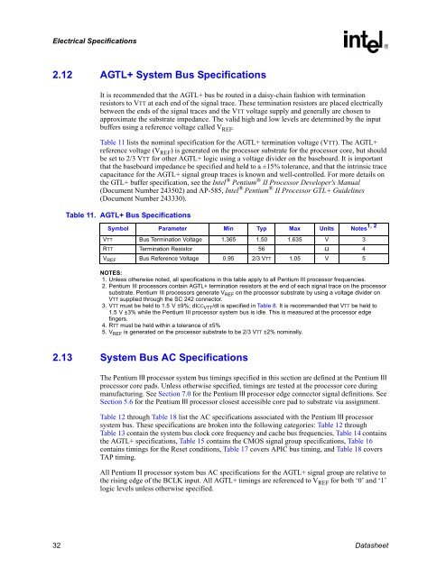
Electrical Specific<strong>at</strong>ions2.12 AGTL+ System Bus Specific<strong>at</strong>ionsIt is recommended th<strong>at</strong> <strong>the</strong> AGTL+ bus be routed in a daisy-chain fashion with termin<strong>at</strong>ionresis<strong>to</strong>rs <strong>to</strong> VTT <strong>at</strong> each end of <strong>the</strong> signal trace. These termin<strong>at</strong>ion resis<strong>to</strong>rs are placed electricallybetween <strong>the</strong> ends of <strong>the</strong> signal traces and <strong>the</strong> VTT voltage supply and generally are chosen <strong>to</strong>approxim<strong>at</strong>e <strong>the</strong> substr<strong>at</strong>e impedance. The valid high and low levels are determined by <strong>the</strong> inputbuffers using a reference voltage called V REF .Table 11 lists <strong>the</strong> nominal specific<strong>at</strong>ion <strong>for</strong> <strong>the</strong> AGTL+ termin<strong>at</strong>ion voltage (VTT). The AGTL+reference voltage (V REF ) is gener<strong>at</strong>ed on <strong>the</strong> processor substr<strong>at</strong>e <strong>for</strong> <strong>the</strong> processor core, but shouldbe set <strong>to</strong> 2/3 VTT <strong>for</strong> o<strong>the</strong>r AGTL+ logic using a voltage divider on <strong>the</strong> baseboard. It is importantth<strong>at</strong> <strong>the</strong> baseboard impedance be specified and held <strong>to</strong> a ±15% <strong>to</strong>lerance, and th<strong>at</strong> <strong>the</strong> intrinsic tracecapacitance <strong>for</strong> <strong>the</strong> AGTL+ signal group traces is known and well-controlled. For more details on<strong>the</strong> GTL+ buffer specific<strong>at</strong>ion, see <strong>the</strong> <strong>Intel</strong> ® <strong>Pentium</strong> ® II <strong>Processor</strong> Developer's Manual(Document Number 243502) and AP-585, <strong>Intel</strong> ® <strong>Pentium</strong> ® II <strong>Processor</strong> GTL+ Guidelines(Document Number 243330).Table 11. AGTL+ Bus Specific<strong>at</strong>ionsSymbol Parameter Min Typ Max Units Notes 1, 2VTT Bus Termin<strong>at</strong>ion Voltage 1.365 1.50 1.635 V 3RTT Termin<strong>at</strong>ion Resis<strong>to</strong>r 56 Ω 4V REF Bus Reference Voltage 0.95 2/3 VTT <strong>1.0</strong>5 V 5NOTES:1. Unless o<strong>the</strong>rwise noted, all specific<strong>at</strong>ions in this table apply <strong>to</strong> all <strong>Pentium</strong> <strong>III</strong> processor frequencies.2. <strong>Pentium</strong> <strong>III</strong> processors contain AGTL+ termin<strong>at</strong>ion resis<strong>to</strong>rs <strong>at</strong> <strong>the</strong> end of each signal trace on <strong>the</strong> processorsubstr<strong>at</strong>e. <strong>Pentium</strong> <strong>III</strong> processors gener<strong>at</strong>e V REF on <strong>the</strong> processor substr<strong>at</strong>e by using a voltage divider onVTT supplied through <strong>the</strong> SC 242 connec<strong>to</strong>r.3. VTT must be held <strong>to</strong> 1.5 V ±9%; dICC VTT /dt is specified in Table 8. It is recommended th<strong>at</strong> VTT be held <strong>to</strong>1.5 V ±3% while <strong>the</strong> <strong>Pentium</strong> <strong>III</strong> processor system bus is idle. This is measured <strong>at</strong> <strong>the</strong> processor edgefingers.4. RTT must be held within a <strong>to</strong>lerance of ±5%5. V REF is gener<strong>at</strong>ed on <strong>the</strong> processor substr<strong>at</strong>e <strong>to</strong> be 2/3 VTT ±2% nominally.2.13 System Bus AC Specific<strong>at</strong>ionsThe <strong>Pentium</strong> <strong>III</strong> processor system bus timings specified in this section are defined <strong>at</strong> <strong>the</strong> <strong>Pentium</strong> <strong>III</strong>processor core pads. Unless o<strong>the</strong>rwise specified, timings are tested <strong>at</strong> <strong>the</strong> processor core duringmanufacturing. See Section 7.0 <strong>for</strong> <strong>the</strong> <strong>Pentium</strong> <strong>III</strong> processor edge connec<strong>to</strong>r signal definitions. SeeSection 5.6 <strong>for</strong> <strong>the</strong> <strong>Pentium</strong> <strong>III</strong> processor closest accessible core pad <strong>to</strong> substr<strong>at</strong>e via assignment.Table 12 through Table 18 list <strong>the</strong> AC specific<strong>at</strong>ions associ<strong>at</strong>ed with <strong>the</strong> <strong>Pentium</strong> <strong>III</strong> processorsystem bus. These specific<strong>at</strong>ions are broken in<strong>to</strong> <strong>the</strong> following c<strong>at</strong>egories: Table 12 throughTable 13 contain <strong>the</strong> system bus clock core frequency and cache bus frequencies, Table 14 contains<strong>the</strong> AGTL+ specific<strong>at</strong>ions, Table 15 contains <strong>the</strong> CMOS signal group specific<strong>at</strong>ions, Table 16contains timings <strong>for</strong> <strong>the</strong> Reset conditions, Table 17 covers APIC bus timing, and Table 18 coversTAP timing.All <strong>Pentium</strong> II processor system bus AC specific<strong>at</strong>ions <strong>for</strong> <strong>the</strong> AGTL+ signal group are rel<strong>at</strong>ive <strong>to</strong><strong>the</strong> rising edge of <strong>the</strong> BCLK input. All AGTL+ timings are referenced <strong>to</strong> V REF <strong>for</strong> both ‘0’ and ‘1’logic levels unless o<strong>the</strong>rwise specified.32 D<strong>at</strong>asheet