<strong>Intel</strong> ® <strong>Pentium</strong> ® <strong>III</strong> <strong>Processor</strong> Signal DescriptionTable 41. Signal Description (Sheet 4 of 7)Name Type DescriptionEMIFERR#FLUSH#HIT#HITM#IERR#IGNNE#INIT#LINT[1:0]IOII/OI/OO<strong>III</strong>EMI pins should be connected <strong>to</strong> baseboard ground and/or <strong>to</strong> chassis groundthrough zero ohm (0 Ω) resis<strong>to</strong>rs. The 0 Ω resis<strong>to</strong>rs should be placed in closeproximity <strong>to</strong> <strong>the</strong> processor connec<strong>to</strong>r. The p<strong>at</strong>h <strong>to</strong> chassis ground should be short inlength and have a low impedance. These pins are used <strong>for</strong> EMI managementpurposes.The FERR# (Flo<strong>at</strong>ing-point Error) signal is asserted when <strong>the</strong> processor detects anunmasked flo<strong>at</strong>ing-point error. FERR# is similar <strong>to</strong> <strong>the</strong> ERROR# signal on <strong>the</strong><strong>Intel</strong> 387 coprocessor, and is included <strong>for</strong> comp<strong>at</strong>ibility with systems usingMS-DOS*-type flo<strong>at</strong>ing-point error reporting.When <strong>the</strong> FLUSH# input signal is asserted, processors write back all d<strong>at</strong>a in <strong>the</strong>Modified st<strong>at</strong>e from <strong>the</strong>ir internal caches and invalid<strong>at</strong>e all internal cache lines. At<strong>the</strong> completion of this oper<strong>at</strong>ion, <strong>the</strong> processor issues a Flush Acknowledgetransaction. The processor does not cache any new d<strong>at</strong>a while <strong>the</strong> FLUSH# signalremains asserted.FLUSH# is an asynchronous signal. However, <strong>to</strong> ensure recognition of this signalfollowing an I/O write instruction, it must be valid along with <strong>the</strong> TRDY# assertion of<strong>the</strong> corresponding I/O Write bus transaction.On <strong>the</strong> active-<strong>to</strong>-inactive transition of RESET#, each processor samples FLUSH#<strong>to</strong> determine its power-on configur<strong>at</strong>ion. See <strong>the</strong> P6 Family of <strong>Processor</strong>s HardwareDeveloper’s Manual (Document Number 244001) <strong>for</strong> details.The HIT# (Snoop Hit) and HITM# (Hit Modified) signals convey transaction snoopoper<strong>at</strong>ion results, and must connect <strong>the</strong> appropri<strong>at</strong>e pins of all processor systembus agents. Any such agent may assert both HIT# and HITM# <strong>to</strong>ge<strong>the</strong>r <strong>to</strong> indic<strong>at</strong>eth<strong>at</strong> it requires a snoop stall, which can be continued by reasserting HIT# andHITM# <strong>to</strong>ge<strong>the</strong>r.The IERR# (Internal Error) signal is asserted by a processor as <strong>the</strong> result of aninternal error. Assertion of IERR# is usually accompanied by a SHUTDOWNtransaction on <strong>the</strong> processor system bus. This transaction may optionally beconverted <strong>to</strong> an external error signal (e.g., NMI) by system core logic. Theprocessor will keep IERR# asserted until <strong>the</strong> assertion of RESET#, BINIT#, orINIT#.The IGNNE# (Ignore Numeric Error) signal is asserted <strong>to</strong> <strong>for</strong>ce <strong>the</strong> processor <strong>to</strong>ignore a numeric error and continue <strong>to</strong> execute noncontrol flo<strong>at</strong>ing-pointinstructions. If IGNNE# is deasserted, <strong>the</strong> processor gener<strong>at</strong>es an exception on anoncontrol flo<strong>at</strong>ing-point instruction if a previous flo<strong>at</strong>ing-point instruction caused anerror. IGNNE# has no effect when <strong>the</strong> NE bit in control register 0 is set.IGNNE# is an asynchronous signal. However, <strong>to</strong> ensure recognition of this signalfollowing an I/O write instruction, it must be valid along with <strong>the</strong> TRDY# assertion of<strong>the</strong> corresponding I/O Write bus transaction.The INIT# (Initializ<strong>at</strong>ion) signal, when asserted, resets integer registers inside allprocessors without affecting <strong>the</strong>ir internal (L1 or L2) caches or flo<strong>at</strong>ing-pointregisters. Each processor <strong>the</strong>n begins execution <strong>at</strong> <strong>the</strong> power-on Reset vec<strong>to</strong>rconfigured during power-on configur<strong>at</strong>ion. The processor continues <strong>to</strong> handlesnoop requests during INIT# assertion. INIT# is an asynchronous signal and mustconnect <strong>the</strong> appropri<strong>at</strong>e pins of all processor system bus agents.If INIT# is sampled active on <strong>the</strong> active <strong>to</strong> inactive transition of RESET#, <strong>the</strong>n <strong>the</strong>processor executes its Built-in Self-Test (BIST).The LINT[1:0] (Local APIC Interrupt) signals must connect <strong>the</strong> appropri<strong>at</strong>e pins ofall APIC Bus agents, including all processors and <strong>the</strong> core logic or I/O APICcomponent. When <strong>the</strong> APIC is disabled, <strong>the</strong> LINT0 signal becomes INTR, amaskable interrupt request signal, and LINT1 becomes NMI, a nonmaskableinterrupt. INTR and NMI are backward comp<strong>at</strong>ible with <strong>the</strong> signals of those nameson <strong>the</strong> <strong>Pentium</strong> processor. Both signals are asynchronous.Both of <strong>the</strong>se signals must be software configured via BIOS programming of <strong>the</strong>APIC register space <strong>to</strong> be used ei<strong>the</strong>r as NMI/INTR or LINT[1:0]. Because <strong>the</strong> APICis enabled by default after Reset, oper<strong>at</strong>ion of <strong>the</strong>se pins as LINT[1:0] is <strong>the</strong> defaultconfigur<strong>at</strong>ion.96 D<strong>at</strong>asheet
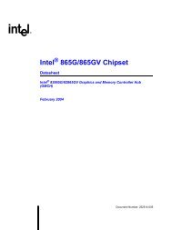
<strong>Intel</strong> ® <strong>Pentium</strong> ® <strong>III</strong> <strong>Processor</strong> Signal DescriptionTable 41. Signal Description (Sheet 5 of 7)Name Type DescriptionLOCK#PICCLKPICD[1:0]PRDY#PREQ#PWRGOODI/OII/OOIIThe LOCK# signal indic<strong>at</strong>es <strong>to</strong> <strong>the</strong> system th<strong>at</strong> a transaction must occur <strong>at</strong>omically.This signal must connect <strong>the</strong> appropri<strong>at</strong>e pins of all processor system bus agents.For a locked sequence of transactions, LOCK# is asserted from <strong>the</strong> beginning of<strong>the</strong> first transaction end of <strong>the</strong> last transaction.When <strong>the</strong> priority agent asserts BPRI# <strong>to</strong> arbitr<strong>at</strong>e <strong>for</strong> ownership of <strong>the</strong> processorsystem bus, it will wait until it observes LOCK# deasserted. This enables symmetricagents <strong>to</strong> retain ownership of <strong>the</strong> processor system bus throughout <strong>the</strong> bus lockedoper<strong>at</strong>ion and ensure <strong>the</strong> <strong>at</strong>omicity of lock.The PICCLK (APIC Clock) signal is an input clock <strong>to</strong> <strong>the</strong> processor and core logic orI/O APIC which is required <strong>for</strong> oper<strong>at</strong>ion of all processors, core logic, and I/O APICcomponents on <strong>the</strong> APIC bus.The PICD[1:0] (APIC D<strong>at</strong>a) signals are used <strong>for</strong> bidirectional serial messagepassing on <strong>the</strong> APIC bus, and must connect <strong>the</strong> appropri<strong>at</strong>e pins of all processorsand core logic or I/O APIC components on <strong>the</strong> APIC bus.The PRDY (Probe Ready) signal is a processor output used by debug <strong>to</strong>ols <strong>to</strong>determine processor debug readiness.The PREQ# (Probe Request) signal is used by debug <strong>to</strong>ols <strong>to</strong> request debugoper<strong>at</strong>ion of <strong>the</strong> processors.The PWRGOOD (Power Good) signal is a 2.5 V <strong>to</strong>lerant processor input. Theprocessor requires this signal <strong>to</strong> be a clean indic<strong>at</strong>ion th<strong>at</strong> <strong>the</strong> clocks and powersupplies (VCC CORE , etc.) are stable and within <strong>the</strong>ir specific<strong>at</strong>ions. Clean impliesth<strong>at</strong> <strong>the</strong> signal will remain low (capable of sinking leakage current), without glitches,from <strong>the</strong> time th<strong>at</strong> <strong>the</strong> power supplies are turned on until <strong>the</strong>y come withinspecific<strong>at</strong>ion. The signal must <strong>the</strong>n transition mono<strong>to</strong>nically <strong>to</strong> a high (2.5 V) st<strong>at</strong>e.The figure below illustr<strong>at</strong>es <strong>the</strong> rel<strong>at</strong>ionship of PWRGOOD <strong>to</strong> o<strong>the</strong>r system signals.PWRGOOD can be driven inactive <strong>at</strong> any time, but clocks and power must again bestable be<strong>for</strong>e a subsequent rising edge of PWRGOOD. It must also meet <strong>the</strong>minimum pulse width specific<strong>at</strong>ion in Table 15, and be followed by a 1 ms RESET#pulse.The PWRGOOD signal must be supplied <strong>to</strong> <strong>the</strong> processor; it is used <strong>to</strong> protectinternal circuits against voltage sequencing issues. It should be driven highthroughout boundary scan oper<strong>at</strong>ion.PWRGOOD Rel<strong>at</strong>ionship <strong>at</strong> Power-OnBCLKV CC,V CCP,V REFPWRGOODV IH,min1 msecRESET#REQ[4:0]#I/OD0026-00The REQ[4:0]# (Request Command) signals must connect <strong>the</strong> appropri<strong>at</strong>e pins ofall processor system bus agents. They are asserted by <strong>the</strong> current bus owner overtwo clock cycles <strong>to</strong> define <strong>the</strong> currently active transaction type.D<strong>at</strong>asheet 97