GREEN HOBBY Assembly Notes for "DAISY" - Green Hobby & Model
GREEN HOBBY Assembly Notes for "DAISY" - Green Hobby & Model
GREEN HOBBY Assembly Notes for "DAISY" - Green Hobby & Model

You also want an ePaper? Increase the reach of your titles
YUMPU automatically turns print PDFs into web optimized ePapers that Google loves.
Now fit the flat stabiliser -elevator onto the rearward tapped holes with two nylon bolts. You can now<br />
see the clear space required under the vertical fin <strong>for</strong> flat stabiliser's free movement in flight. Trial fit fin<br />
again until completely satisfied.<br />
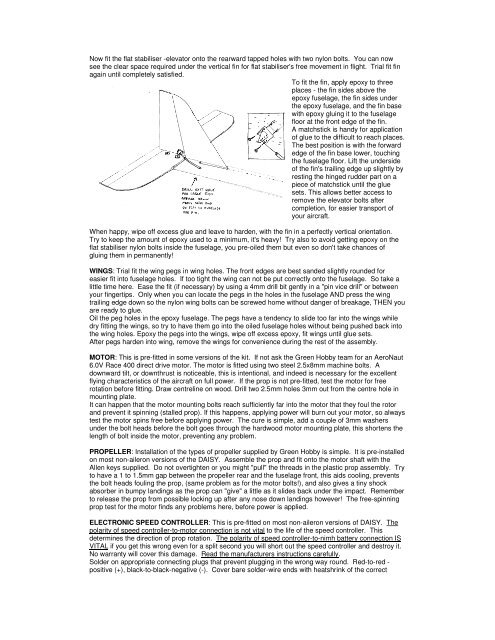
To fit the fin, apply epoxy to three<br />
places - the fin sides above the<br />
epoxy fuselage, the fin sides under<br />
the epoxy fuselage, and the fin base<br />
with epoxy gluing it to the fuselage<br />
floor at the front edge of the fin.<br />
A matchstick is handy <strong>for</strong> application<br />
of glue to the difficult to reach places.<br />
The best position is with the <strong>for</strong>ward<br />
edge of the fin base lower, touching<br />
the fuselage floor. Lift the underside<br />
of the fin's trailing edge up slightly by<br />
resting the hinged rudder part on a<br />
piece of matchstick until the glue<br />
sets. This allows better access to<br />
remove the elevator bolts after<br />
completion, <strong>for</strong> easier transport of<br />
your aircraft.<br />
When happy, wipe off excess glue and leave to harden, with the fin in a perfectly vertical orientation.<br />
Try to keep the amount of epoxy used to a minimum, it's heavy! Try also to avoid getting epoxy on the<br />
flat stabiliser nylon bolts inside the fuselage, you pre-oiled them but even so don't take chances of<br />
gluing them in permanently!<br />
WINGS: Trial fit the wing pegs in wing holes. The front edges are best sanded slightly rounded <strong>for</strong><br />
easier fit into fuselage holes. If too tight the wing can not be put correctly onto the fuselage. So take a<br />
little time here. Ease the fit (if necessary) by using a 4mm drill bit gently in a "pin vice drill" or between<br />
your fingertips. Only when you can locate the pegs in the holes in the fuselage AND press the wing<br />
trailing edge down so the nylon wing bolts can be screwed home without danger of breakage, THEN you<br />
are ready to glue.<br />
Oil the peg holes in the epoxy fuselage. The pegs have a tendency to slide too far into the wings while<br />
dry fitting the wings, so try to have them go into the oiled fuselage holes without being pushed back into<br />
the wing holes. Epoxy the pegs into the wings, wipe off excess epoxy, fit wings until glue sets.<br />
After pegs harden into wing, remove the wings <strong>for</strong> convenience during the rest of the assembly.<br />
MOTOR: This is pre-fitted in some versions of the kit. If not ask the <strong>Green</strong> <strong>Hobby</strong> team <strong>for</strong> an AeroNaut<br />
6.0V Race 400 direct drive motor. The motor is fitted using two steel 2.5x8mm machine bolts. A<br />
downward tilt, or downthrust is noticeable, this is intentional, and indeed is necessary <strong>for</strong> the excellent<br />
flying characteristics of the aircraft on full power. If the prop is not pre-fitted, test the motor <strong>for</strong> free<br />
rotation be<strong>for</strong>e fitting. Draw centreline on wood. Drill two 2.5mm holes 3mm out from the centre hole in<br />
mounting plate.<br />
It can happen that the motor mounting bolts reach sufficiently far into the motor that they foul the rotor<br />
and prevent it spinning (stalled prop). If this happens, applying power will burn out your motor, so always<br />
test the motor spins free be<strong>for</strong>e applying power. The cure is simple, add a couple of 3mm washers<br />
under the bolt heads be<strong>for</strong>e the bolt goes through the hardwood motor mounting plate, this shortens the<br />
length of bolt inside the motor, preventing any problem.<br />
PROPELLER: Installation of the types of propeller supplied by <strong>Green</strong> <strong>Hobby</strong> is simple. It is pre-installed<br />
on most non-aileron versions of the DAISY. Assemble the prop and fit onto the motor shaft with the<br />
Allen keys supplied. Do not overtighten or you might "pull" the threads in the plastic prop assembly. Try<br />
to have a 1 to 1.5mm gap between the propeller rear and the fuselage front, this aids cooling, prevents<br />
the bolt heads fouling the prop, (same problem as <strong>for</strong> the motor bolts!), and also gives a tiny shock<br />
absorber in bumpy landings as the prop can "give" a little as it slides back under the impact. Remember<br />
to release the prop from possible locking up after any nose down landings however! The free-spinning<br />
prop test <strong>for</strong> the motor finds any problems here, be<strong>for</strong>e power is applied.<br />
ELECTRONIC SPEED CONTROLLER: This is pre-fitted on most non-aileron versions of DAISY. The<br />
polarity of speed controller-to-motor connection is not vital to the life of the speed controller. This<br />
determines the direction of prop rotation. The polarity of speed controller-to-nimh battery connection IS<br />
VITAL if you get this wrong even <strong>for</strong> a split second you will short out the speed controller and destroy it.<br />
No warranty will cover this damage. Read the manufacturers instructions carefully.<br />
Solder on appropriate connecting plugs that prevent plugging in the wrong way round. Red-to-red -<br />
positive (+), black-to-black-negative (-). Cover bare solder-wire ends with heatshrink of the correct