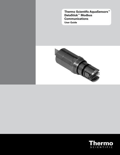
Thermo Scientific AquaSensors™ DataStick™ Modbus ...
Thermo Scientific AquaSensors™ DataStick™ Modbus ...
Thermo Scientific AquaSensors™ DataStick™ Modbus ...

You also want an ePaper? Increase the reach of your titles
YUMPU automatically turns print PDFs into web optimized ePapers that Google loves.
<strong>Thermo</strong> <strong>Scientific</strong> AquaSensors <br />
DataStick <strong>Modbus</strong><br />
Communications<br />
User Guide
ROSS and the COIL trade dress are trademarks of <strong>Thermo</strong> Fisher <strong>Scientific</strong> Inc. U.S. patent 6,793,787.<br />
AQUAfast, Cahn, ionplus, KNIpHE, No Cal, ORION, perpHect, PerpHecT, PerpHecTion, pHISA, pHuture, Pure Water, Sage, Sensing the Future, SensorLink,<br />
ROSS, ROSS Ultra, Sure-Flow, Titrator PLUS and TURBO2 are registered trademarks of <strong>Thermo</strong> Fisher.<br />
1-888-pHAX-ION, A+, All in One, Aplus, AQUAsnap, AssuredAccuracy, AUTO-BAR, AUTO-CAL, AUTO DISPENSER, Auto-ID, AUTO-LOG, AUTO-READ,<br />
AUTO-STIR, Auto-Test, BOD AutoEZ, Cable-Free, CERTI-CAL, CISA, DataCOLLECT, DataPLUS, digital LogR, DirectCal, DuraProbe, Environmental Product<br />
Authority, Extra Easy/Extra Value, FAST QC, GAP, GLPcal, GLPcheck, GLPdoc, ISEasy, KAP, LabConnect, LogR, Low Maintenance Triode, Minimum Stir<br />
Requirement, MSR, NISS, One-Touch, One-Touch Calibration, One-Touch Measurement, Optimum Results, Orion Star, Pentrode, pHuture MMS, pHuture<br />
Pentrode, pHuture Quatrode, pHuture Triode, Quatrode, QuiKcheK, rf link, ROSS Resolution, SAOB, SMART AVERAGING, Smart CheK, SMART STABILITY,<br />
Stacked, Star Navigator 21, Stat Face, The Enhanced Lab, ThermaSense, Triode, TRIUMpH, Unbreakable pH, Universal Access are trademarks of<br />
<strong>Thermo</strong> Fisher.<br />
Guaranteed Success and The Technical Edge are service marks of <strong>Thermo</strong> Fisher.<br />
PerpHecT meters are protected by U.S. patent 6,168,707.<br />
PerpHecT ROSS electrodes are protected by U.S. patent 6,168,707.<br />
ORION Series A meters and 900A printer are protected by U.S. patents 5,198,093, D334,208 and D346,753.<br />
ionplus electrodes and Optimum Results solutions are protected by U.S. patent 5,830,338.<br />
ROSS Ultra electrodes are protected by U.S. patent 6,793,787.<br />
ORP standard is protected by U.S. patent 6,350,367.<br />
No Cal electrodes are protected by U.S. patent 7,276,142.<br />
© 2009 <strong>Thermo</strong> Fisher <strong>Scientific</strong> Inc. All rights reserved. All trademarks are the property of <strong>Thermo</strong> Fisher <strong>Scientific</strong> Inc. and its subsidiaries.<br />
The specifications, descriptions, drawings, ordering information and part numbers within this document are subject to change without notice.<br />
This publication supersedes all previous publications on this subject.
Table of Contents<br />
1 Introduction.................................................................................................................................. 2<br />
2 Hardware Setup ........................................................................................................................... 3<br />
3 Communications Parameter Configuration via Fieldbus........................................................... 6<br />
3.1 Default Communications Parameters...................................................................................... 6<br />
3.2 <strong>Modbus</strong> Slave Address ........................................................................................................... 6<br />
3.3 <strong>Modbus</strong> Baud Rate ................................................................................................................. 6<br />
3.4 <strong>Modbus</strong> Parity ........................................................................................................................ 7<br />
3.5 Restoring Default Slave Address, Baud Rate, and Parity......................................................... 8<br />
4 Function Codes............................................................................................................................. 9<br />
5 Register Numbers and Byte/Word Order ................................................................................. 10<br />
5.1 Variable Classes ................................................................................................................... 11<br />
5.1.1 Class Process Value...................................................................................................... 11<br />
5.1.2 Class Scale Factor......................................................................................................... 11<br />
5.1.3 Class Configuration Value ............................................................................................ 12<br />
5.1.4 Class Information ......................................................................................................... 12<br />
5.1.5 Class Calibration........................................................................................................... 12<br />
5.1.6 Class Status .................................................................................................................. 12<br />
6 <strong>Modbus</strong> Register Map................................................................................................................ 14<br />
6.1 Embedded in an AV38 ......................................................................................................... 20<br />
7 References................................................................................................................................... 20<br />
8 Limited Warranty...................................................................................................................... 21<br />
9 Terms and Conditions................................................................................................................ 22<br />
Contact Information<br />
To contact <strong>Thermo</strong> <strong>Scientific</strong> AquaSensors Technical Support:<br />
Within the United States call 1.800.225.1480 or fax 978-232-6015.<br />
Outside the United States call 978.232.6000 or fax 978.232.6031.<br />
In Europe, the Middle East and Africa, contact your local authorized dealer.<br />
Visit us on the web at www.thermo.com/processwater<br />
<strong>Modbus</strong> Adapter Part Numbers:<br />
• CA12B: 316 Stainless Steel Housing<br />
• CA22B: CPVC Housing<br />
• CA32B: PEEK® Housing<br />
• CA42B: Ryton® Housing<br />
<strong>Thermo</strong> <strong>Scientific</strong> AquaSensors DataStick <strong>Modbus</strong> Communications User Guide 1
1 Introduction<br />
The <strong>Thermo</strong> <strong>Scientific</strong> AquaSensors <strong>Modbus</strong> Adapter is a gateway between any DataStick measurement<br />
system and a <strong>Modbus</strong> master. It regulates external power and provides full-featured interactive<br />
measurement, calibration, configuration, and diagnostic features without the need for an intermediate<br />
analyzer or controller.<br />
The Adapter register map can be used for direct access to measure, calibrate, configure, and diagnose<br />
information, even when the sensor head is changed from one type of analytical measurement to another<br />
with power applied. The registers support both floating-point and integer variables. Some status<br />
information is passed as an ASCII string. Open protocol ASCII commands and responses are also<br />
supported for applications that require direct control of message traffic.<br />
The <strong>Modbus</strong> Adapter must be configured with the correct Baud rate, parity, and station address. This<br />
can be done at the factory or in the field. The configured station address, Baud rate, and parity stay with<br />
the Adapter even when the DataStick is removed from the system.<br />
Table 1: Register Map Overview<br />
Start End Description<br />
40001 40016 ASCII Command up to 32 bytes is directly passed to the DataStick.<br />
40017 40032<br />
40033 40048 ASCII Response up to 32 bytes in response to an ASCII command.<br />
40049 41000<br />
41001 41006 Operational status registers. Integer.<br />
41007 42000<br />
42001 42004 Read process values. Floating point.<br />
42005 42010 Write sample calibration values. Floating point.<br />
42011 42022<br />
42023 42032 Write configuration data. Floating point.<br />
42033 43000<br />
43001 43027 Read/Write Measure, Calibration and Configuration data. Integers.<br />
43028 44000<br />
44001 44005 Read Scale Factors. Integers.<br />
44006 45000<br />
45001 45020 Read/Write Sensor Information as ASCII.<br />
45021 45024 Read/Write Sensor Information as Integer.<br />
The DataStick automatically supports multiple measurement types and, if all configuration and<br />
calibration registers are used, all sensor heads can be automatically supported.<br />
Refer to the DataStick Manual for detailed information on installation, maintenance and operation.<br />
<strong>Thermo</strong> <strong>Scientific</strong> AquaSensors DataStick <strong>Modbus</strong> Communications User Guide 2
2 Hardware Setup<br />
The DataStick consists of three parts that are assembled at the factory:<br />
1. Plug-in <strong>Modbus</strong> Adapter<br />
2. Universal Sensor Module<br />
3. Plug-in Sensor Head<br />
The following is excerpted from “Ten Ways to Bulletproof RS-485 Interfaces”, National Semiconductor<br />
Application Note 1057:<br />
The optimal configuration for the RS-485 bus is the daisy-chain connection from node 1 to<br />
node 2 to node 3 to node n. The bus must form a single continuous path, and the nodes in the<br />
middle of the bus must not be at the ends of long branches, spokes, or stubs. Connecting a<br />
node to the cable creates a stub, and, therefore, every node has a stub. Minimizing the stub<br />
length minimizes transmission-line problems. A good rule is to make the stubs as short as<br />
possible.<br />
There are several options for terminating an RS-485 bus. The first option is no termination.<br />
This option is feasible if the cable is short and if the data rate is low. Reflections occur, but<br />
they settle after about three round-trip delays. For a short-cable, the round-trip delay is<br />
short and, if the data rate is low, the unit interval is long. Under these conditions, the<br />
reflections settle out before sampling, which occurs at the middle of the bit interval.<br />
The most popular termination option is to connect a single resistor across the conductor pair<br />
at each end. The resistor value matches the cable’s differential-mode characteristic<br />
impedance. If the bus is terminated in this way, no reflections occur, and the signal fidelity is<br />
excellent. The problem with this termination option is the power dissipated in the<br />
termination resistors.<br />
If power dissipation must be minimized, an RC termination may be the solution. In place of<br />
the single resistor, a resistor in series with a capacitor is used. The capacitor appears as a<br />
short circuit during transitions, and the resistor terminates the line. Once the capacitor<br />
charges, it blocks the DC loop current and presents a light load to the driver. Low-pass<br />
effects limit the use of the RC termination to lower data-rate applications, however.<br />
<strong>Thermo</strong> <strong>Scientific</strong> AquaSensors DataStick <strong>Modbus</strong> Communications User Guide 3
The characteristic impedance of the cable supplied with the <strong>Modbus</strong> Communications Adapter is 120 .<br />
A <strong>Modbus</strong> Communications Adapter does not have an integral termination resistor, so the stub created<br />
by its integral cable must be kept as short as possible. This can be accomplished by locating the junction<br />
box as close as possible to the <strong>Modbus</strong> Communications Adapter.<br />
For applications involving a single <strong>Modbus</strong> Communications Adapter, a termination resistor should be<br />
placed across the bus at the master and also across the bus in a junction box located as close as possible<br />
to the <strong>Modbus</strong> Communications Adapter.<br />
For applications involving multiple <strong>Modbus</strong> Communications Adapters, a termination resistor should be<br />
placed across the bus at each end.<br />
The standard cable length for a <strong>Modbus</strong> Adapter is 10 feet, and it comes with wires that are stripped and<br />
tinned for use with terminal blocks. A water-resistant label is placed at the end of the cable that<br />
provides a chart of wire colors and functions for use with <strong>Modbus</strong> running on RS-485 (Part number<br />
CA22B) or RS-232 (Part number CA22A). Be sure the correct model is being used.<br />
Any Class II power supply that provides 10 to 30 volts may be used to power the DataStick<br />
measurement system. The power ground and the signal ground MUST be connected together at the<br />
power source for the <strong>Modbus</strong> Adapter to operate correctly.<br />
The shield wire must be connected to ensure proper electromagnetic immunity from other electrical<br />
equipment.<br />
Table 2: <strong>Modbus</strong> Wiring<br />
RS-485 RS-232 Wire Color<br />
Hardware Hardware<br />
10 to 30 VDC 10 to 30 VDC RED<br />
Signal Ground Signal Ground BLACK<br />
Comms (–) Comms (Rx) BLUE<br />
Comms (+) Comms (Tx) WHITE<br />
Earth Earth SHIELD<br />
<strong>Thermo</strong> <strong>Scientific</strong> AquaSensors DataStick <strong>Modbus</strong> Communications User Guide 4
The <strong>Modbus</strong> Adapter can be removed and replaced in the field. This may be desirable for any number<br />
of reasons, some of which include:<br />
• Diagnostics: Temporarily plug in a USB adapter for PC diagnostics<br />
• Feature Upgrade: Temporarily plug in a programming adapter to load new code<br />
• Repair: Replace a damaged DataStick assembly without rewiring<br />
• Change Measurement: Quick sensor swap<br />
The <strong>Modbus</strong> Adapter is keyed and plugs into the end of the DataStick Universal Sensor Module that is<br />
marked “Communications Adapter”.<br />
Insert the <strong>Modbus</strong> Adapter until it bottoms out. Rotate the Adapter until it engages with the connector.<br />
Push the adapter in gently, and then tighten the retaining ring with a 15/16-inch wrench. It is very<br />
important to tighten the retaining ring to ensure a reliable connection.<br />
Retaining ring. Rotate clockwise to<br />
tighten. Use a 15/16-inch wrench.<br />
Potted Serial Number and<br />
Part Number.<br />
O-Ring seal should be free of<br />
dirt when inserted into the<br />
DataStick.<br />
<strong>Thermo</strong> <strong>Scientific</strong> AquaSensors DataStick <strong>Modbus</strong> Communications User Guide 5
3 Communications Parameter Configuration via Fieldbus<br />
Communications parameter configuration involves setting the slave address, Baud rate, and parity of the<br />
<strong>Modbus</strong> Adapter’s fieldbus port using a freely available tool such as ModScan32 from WinTECH<br />
Software Design (http://www.win-tech.com/html/modscan32.htm).<br />
NOTE: New communications settings for slave address, Baud rate, and parity do not take effect<br />
until power to the <strong>Modbus</strong> Adapter is cycled!<br />
3.1 Default Communications Parameters<br />
The default communications parameters are:<br />
• Slave address: 1<br />
• Baud Rate: 19.2 kbps<br />
• Data Bits: 8<br />
• Stop Bits: 1<br />
• Parity: Odd<br />
These parameters are set at the factory unless custom parameters have been requested. If the parameters<br />
are customized, the <strong>Modbus</strong> Adapter will be accompanied by a paper tag that indicates the custom<br />
parameters.<br />
3.2 <strong>Modbus</strong> Slave Address<br />
Register Address: 43022<br />
Default Value: 1<br />
Supported Slave Values: 1 to 247<br />
Units: N/A<br />
This slave address specifies the station number of the DataStick on the <strong>Modbus</strong> network. It must be a<br />
unique station number on the network and can be any value from 1 to 247. Read register 43022 to<br />
obtain the current station number. Write to the same register to change it.<br />
3.3 <strong>Modbus</strong> Baud Rate<br />
Register Address: 43023<br />
Default Value: 0 (19.2 kbps)<br />
Supported Values: 1.2 kbps to 230.4 kbps<br />
Units: kbps (kilobits per second)<br />
The Baud rate specifies the speed at which data is transferred between the <strong>Modbus</strong> master and the<br />
<strong>Modbus</strong> adapter. Read register 43023 to obtain the current Baud rate. Write to the same register to<br />
change it using the integer value in the following table.<br />
<strong>Thermo</strong> <strong>Scientific</strong> AquaSensors DataStick <strong>Modbus</strong> Communications User Guide 6
Table 3: Supported Baud Rates<br />
Baud Rate Integer Value<br />
19.2 kbps (Default) 0<br />
1.2 kbps 1<br />
2.4 kbps 2<br />
4.8 kbps 3<br />
9.6 kbps 4<br />
14.4 kbps 5<br />
19.2 kbps 6<br />
28.8 kbps 7<br />
38.4 kbps 8<br />
57.6 kbps 9<br />
76.8 kbps 10<br />
115.2 kbps 11<br />
230.4 kbps 12<br />
3.4 <strong>Modbus</strong> Parity<br />
Register Address: 43024<br />
Default Value: 0 (Odd)<br />
Supported Values: Odd, None and Even.<br />
Units: N/A<br />
The parity specifies the parity between the <strong>Modbus</strong> master and the <strong>Modbus</strong> Adapter. Read register<br />
43024 to obtain the current parity. Write to the same register to change it using the integer values in the<br />
following table.<br />
Table 4: Parity<br />
Parity Integer Value<br />
Odd (Default) 0<br />
None 1<br />
Odd 2<br />
Even 3<br />
<strong>Thermo</strong> <strong>Scientific</strong> AquaSensors DataStick <strong>Modbus</strong> Communications User Guide 7
3.5 Restoring Default Slave Address, Baud Rate, and Parity<br />
In the event that the slave address, Baud rate, and parity of a <strong>Modbus</strong> Communications Adapter is<br />
unknown, its communications settings can be restored to factory default values by following the<br />
procedure below:<br />
Pin 1<br />
Pin 2<br />
Pin 5 Pin 9<br />
Figure 1: The pin numbering of the DataStick-end of the Adapter.<br />
1. Disconnect the Adapter from the network. Attention: Determine how your control system<br />
will respond before disconnecting an Adapter from the network.<br />
2. Detach the Adapter from the DataStick.<br />
3. Make an electrical connection between pins 5 and 9 on the DataStick-side of the Adapter using a<br />
clip lead or equivalent as shown in Figure 1. Be careful to make the connection only between<br />
pins 5 and 9.<br />
4. Apply power to the Adapter and wait at least 10 seconds.<br />
5. Disconnect the power from the Adapter and remove the electrical connection between pins 5 and<br />
9. Re-attach the Adapter to the DataStick.<br />
6. Establish communications with the Adapter using a protocol of <strong>Modbus</strong> RTU, a slave address of<br />
1, a Baud rate of 19.2 kbps, and a parity of odd.<br />
<strong>Thermo</strong> <strong>Scientific</strong> AquaSensors DataStick <strong>Modbus</strong> Communications User Guide 8
4 Function Codes<br />
The <strong>Modbus</strong> Adapter supports the Remote Terminal Unit (RTU) mode of serial transmission. Further, it<br />
supports the <strong>Modbus</strong> Function Codes shown in Table 5.<br />
Table 5: Supported <strong>Modbus</strong> Function Codes<br />
Code Name<br />
03 Read Holding Registers<br />
06 Preset Single Register<br />
16 Preset Multiple Registers<br />
<strong>Modbus</strong> Function Codes are defined in the <strong>Modbus</strong> Application Protocol Specification, V1.1. If the<br />
function code contained in a query is not supported, the <strong>Modbus</strong> Adapter will respond with an Exception<br />
Code of 01 indicating an illegal function.<br />
<strong>Thermo</strong> <strong>Scientific</strong> AquaSensors DataStick <strong>Modbus</strong> Communications User Guide 9
5 Register Numbers and Byte/Word Order<br />
According to the Modicon Compact 984 Ladder Logic Manual, 043503387, the I/O Reference<br />
Numbering System defines reference number 4XXXX as “an output or holding register. A 4X register<br />
may be used to store numerical data (binary or decimal) in state RAM or to send the data from the CPU<br />
to an output unit in the control system.” For this reason, the register map for the <strong>Modbus</strong> Adapter is<br />
defined to begin at 40,001. The <strong>Modbus</strong> Adapter is the CPU in the above statement, and the customer’s<br />
<strong>Modbus</strong> master is the output unit in the control system.<br />
As defined, some registers are read/write; some are read-only, and some are write-only. If a write-only<br />
register is read by the <strong>Modbus</strong> master, the register’s value will be 0.<br />
The defined registers are grouped into banks so that all registers in a bank can be read with a single<br />
<strong>Modbus</strong> read request. If the register number received in a query is outside the range of the defined<br />
banks, the <strong>Modbus</strong> Adapter will respond with an Exception Code of 02 indicating an illegal data<br />
address. The legality of some register numbers depends on the type of Sensor Head installed in the<br />
DataStick. For example, the Cell Constant register is legal only if a Contacting Conductivity or<br />
Electrodeless Conductivity Sensor Head is installed in the DataStick. DataStick commands and<br />
responses are defined in Section 7 of this document. If the register number received in a query is<br />
invalid, the <strong>Modbus</strong> Adapter will respond with a value of 0. It is the responsibility of the PLC<br />
programmer to know which register numbers are valid based on the Sensor Type.<br />
For consistency, all values of data type float are aligned at even-numbered registers.<br />
Values of type float are represented in 32-bit IEEE 754 floating-point format. This requires two<br />
registers per value. By default, the lower register number contains the upper 16 bits and the higher<br />
register number contains the lower 16 bits as shown in Table 6. This is known as “Big-Endian” word<br />
order. Floats can be made Little-Endian in their word order by changing the value of the PLC Data<br />
Type accordingly as shown in Table 7. The byte order can also be affected by PLC Data Type. For<br />
compatibility with <strong>Thermo</strong> <strong>Scientific</strong> AquaSensors products such as AquaComm and the AV38, set PLC<br />
Data Type to Big Endian (2).<br />
Table 6: Word order of values of type float<br />
42001<br />
42002<br />
Upper 16 bits<br />
Lower 16 bits<br />
Sensor Value (float)<br />
FPConvert can be used to determine hexadecimal representations of floating-point values (and vice<br />
versa). This utility can be obtained from http://www.61131.com.<br />
Table 7: Defines the valid values for PLC Data Type.<br />
Value Type<br />
0 Little Endian – ControlLogix<br />
1 (default) Little Endian Word Swap – SLC<br />
2 Big Endian<br />
3 Big Endian Word Swap<br />
<strong>Thermo</strong> <strong>Scientific</strong> AquaSensors DataStick <strong>Modbus</strong> Communications User Guide 10
The <strong>Modbus</strong> adapter responds with an exception if both registers of a float data type are not read or<br />
written in the same request. This will reduce the likelihood of data corruption within the <strong>Modbus</strong><br />
Master.<br />
There exist three banks of registers that deserve further discussion. They are banks 42XXX, 43XXX,<br />
and 44XXX. Register bank 42XXX contains Process Value, Calibration, and Configuration variables of<br />
type float. Register bank 43XXX contains the same Process Value, Calibration, and Configuration<br />
variables, but of type integer. Register bank 44XXX contains the corresponding Scale Factors for the<br />
integer variables in bank 43XXX. The order of the variables in banks 43XXX and 44XXX is identical<br />
so that a <strong>Modbus</strong> master can access the Scale Factor for an integer Process Value simply by adding<br />
1,000 to the integer Process Value register number.<br />
5.1 Variable Classes<br />
The class of each variable is shown in the register map in Section 6 of this manual. Please note that<br />
there is not a one-to-one correspondence between variables and registers. This is because variables of<br />
type float each occupy two registers.<br />
To make <strong>Modbus</strong> master programming easier, variables of each class are grouped together in the register<br />
map in banks. Each bank is 1,000 registers in size, but the number of variables defined in each bank is<br />
restricted to fewer than 100 so they can all be read/written by a single <strong>Modbus</strong> read/write request.<br />
5.1.1 Class Process Value<br />
This class of variable represents the current value of the process that is being measured by the DataStick.<br />
For example, a pH sensor installed at a wastewater treatment plant might measure the pH of the treated<br />
water leaving the plant. The Sensor Value may be monitored continuously by the plant operator and<br />
may be recorded to demonstrate compliance with applicable EPA regulations.<br />
This class of variable originates in the DataStick and exists in two types; float and integer. The former<br />
is for <strong>Modbus</strong> masters that support floating-point math, and the latter is for <strong>Modbus</strong> masters that do not.<br />
5.1.2 Class Scale Factor<br />
Variables of this class are of type integer.<br />
5.1.2.1 Integer representation of Floating Point numbers<br />
Not all PLC’s support floating-point math. For this reason all values of type float are also available as<br />
type integer.<br />
Integer data types include a corresponding Scale Factor that defines the relationship between the integer<br />
type of the value and the float type.<br />
The <strong>Modbus</strong> Adapter calculates the integer type of the value from the float type by multiplying the float<br />
type by the scale factor. For example, for a Sensor Type of pH, the Scale Factor for the Sensor Value is<br />
100. If the float Sensor Value is 7.04, then the integer Sensor Value is 7.04 x 100 = 704.<br />
<strong>Thermo</strong> <strong>Scientific</strong> AquaSensors DataStick <strong>Modbus</strong> Communications User Guide 11
5.1.2.2 Scale Factors<br />
Most Scale Factors are fixed, e.g., the Cell Constant Scale Factor is fixed at 1000, but some depend on<br />
the type of Sensor Head installed in the DataStick. The Sensor Value Scale Factor is one of these. For<br />
example, when the installed Sensor Head is pH, the Sensor Value Scale Factor is 100, but when the<br />
installed Sensor Head is ORP, the Sensor Value Scale Factor is 1.<br />
5.1.3 Class Configuration Value<br />
This class of variable represents a value that configures some aspect of the operation of the DataStick,<br />
e.g., Sensor Units, or the <strong>Modbus</strong> Adapter. Variables of this class are static, non-volatile, and are stored<br />
in the DataStick or the <strong>Modbus</strong> Adapter.<br />
This class of variable exists in two types: integer and float.<br />
5.1.4 Class Information<br />
This class of variable is used for informational purposes only. Variables of this class are static, nonvolatile,<br />
and are stored in the DataStick, e.g., Main Serial Number.<br />
This class of variable exists in two types: integer and ASCII. All of them have been grouped into a<br />
single register bank.<br />
5.1.5 Class Calibration<br />
This class of variable instructs the DataStick to perform the action of calibrating itself. All calibrations<br />
involve a multi-step procedure, and one of the steps involves writing a calibration variable.<br />
5.1.6 Class Status<br />
All variables of class Status have been grouped into a single register bank.<br />
5.1.6.1 Originating in the DataStick<br />
This class of variable is used for indicating the status of the DataStick, e.g., Calibration Status.<br />
However, variables of this class are not static.<br />
Variables of this class are of type integer.<br />
5.1.6.2 Originating in the <strong>Modbus</strong> Adapter<br />
There is a unique Status variable that originates in the <strong>Modbus</strong> Adapter itself called Communications<br />
Status. The values that this variable can take on are defined in Table 8. On power-up, when<br />
communication has started but before the <strong>Modbus</strong> Adapter has read the Sensor and Temperature Values<br />
from the DataStick, Communications Status is Okay; while the DataStick is absent, Communications<br />
Status is “Communications error”; and, while the <strong>Modbus</strong> Adapter is communicating with the<br />
DataStick, Communications Status is “Data is valid”.<br />
This variable is of type integer.<br />
<strong>Thermo</strong> <strong>Scientific</strong> AquaSensors DataStick <strong>Modbus</strong> Communications User Guide 12
Table 8: Communications Status variable values and their meaning<br />
Value Meaning<br />
0 Okay<br />
1 Communications error<br />
2 Data is valid<br />
<strong>Thermo</strong> <strong>Scientific</strong> AquaSensors DataStick <strong>Modbus</strong> Communications User Guide 13
6 <strong>Modbus</strong> Register Map<br />
Table 9: <strong>Modbus</strong> Adapter Register Map Definition<br />
Register<br />
Number<br />
Description Data<br />
Type<br />
Access DataStick<br />
Command<br />
Example Variable<br />
Class<br />
40001 Command01 ASCII[2] W see Example column "GS" N/A<br />
40002 Command02 ASCII[2] W see Example column "NS" N/A<br />
40003 Command03 ASCII[2] W see Example column "R" N/A<br />
40004 Command04 ASCII[2] W see Example column N/A<br />
40005 Command05 ASCII[2] W see Example column N/A<br />
40006 Command06 ASCII[2] W see Example column N/A<br />
40007 Command07 ASCII[2] W see Example column N/A<br />
40008 Command08 ASCII[2] W see Example column N/A<br />
40009 Command09 ASCII[2] W see Example column N/A<br />
40010 Command10 ASCII[2] W see Example column N/A<br />
40011 Command11 ASCII[2] W see Example column N/A<br />
40012 Command12 ASCII[2] W see Example column N/A<br />
40013 Command13 ASCII[2] W see Example column N/A<br />
40014 Command14 ASCII[2] W see Example column N/A<br />
40015 Command15 ASCII[2] W see Example column N/A<br />
40016 Command16 ASCII[2] W see Example column N/A<br />
40017 Reserved01<br />
40018 Reserved02<br />
40019 Reserved03<br />
40020 Reserved04<br />
40021 Reserved05<br />
40022 Reserved06<br />
40023 Reserved07<br />
40024 Reserved08<br />
40025 Reserved09<br />
40026 Reserved10<br />
40027 Reserved11<br />
40028 Reserved12<br />
40029 Reserved13<br />
40030 Reserved14<br />
40031 Reserved15<br />
40032 Reserved16<br />
40033 Response01 ASCII[2] R N/A "7." N/A<br />
40034 Response02 ASCII[2] R N/A "04" N/A<br />
40035 Response03 ASCII[2] R N/A N/A<br />
40036 Response04 ASCII[2] R N/A N/A<br />
40037 Response05 ASCII[2] R N/A N/A<br />
40038 Response06 ASCII[2] R N/A N/A<br />
40039 Response07 ASCII[2] R N/A N/A<br />
<strong>Thermo</strong> <strong>Scientific</strong> AquaSensors DataStick <strong>Modbus</strong> Communications User Guide 14
Register<br />
Number<br />
Description Data<br />
Type<br />
Access DataStick<br />
Command<br />
Example Variable<br />
Class<br />
40040 Response08 ASCII[2] R N/A N/A<br />
40041 Response09 ASCII[2] R N/A N/A<br />
40042 Response10 ASCII[2] R N/A N/A<br />
40043 Response11 ASCII[2] R N/A N/A<br />
40044 Response12 ASCII[2] R N/A N/A<br />
40045 Response13 ASCII[2] R N/A N/A<br />
40046 Response14 ASCII[2] R N/A N/A<br />
40047 Response15 ASCII[2] R N/A N/A<br />
40048 Response16 ASCII[2] R N/A N/A<br />
40049 Reserved17<br />
40050 Reserved18<br />
40051 Reserved19<br />
40052 Reserved20<br />
40053 Reserved21<br />
40054 Reserved22<br />
40055 Reserved23<br />
40056 Reserved24<br />
40057 Reserved25<br />
40058 Reserved26<br />
40059 Reserved27<br />
40060 Reserved28<br />
40061 Reserved29<br />
40062 Reserved30<br />
40063 Reserved31<br />
40064<br />
…<br />
Reserved32<br />
41001 Communications<br />
Status<br />
integer R N/A Status<br />
41002 Calibration Status integer R CALSTATUS 1 Status<br />
41003 Sensor Memory<br />
Status<br />
integer R GSTATUS 1 Status<br />
41004 Configuration<br />
Memory Status<br />
integer R GSTATUS 1 Status<br />
41005 Calibration Memory<br />
Status<br />
integer R GSTATUS 1 Status<br />
41006<br />
…<br />
Run Status integer R GSTATUS 1 Status<br />
42001 Sensor Value float R GSNSR 7.04 Process<br />
Value<br />
42002 "<br />
42003 Temperature Value float R GTEMP 25.1 Process<br />
Value<br />
<strong>Thermo</strong> <strong>Scientific</strong> AquaSensors DataStick <strong>Modbus</strong> Communications User Guide 15
Register<br />
Number<br />
Description Data<br />
Type<br />
42004 "<br />
42005 Cal Sensor 1-Point<br />
Sample Value<br />
42006 "<br />
42007 Cal Sensor 2-Point<br />
Sample Value<br />
42008 "<br />
42009 Cal Temperature 1-<br />
Point Sample Value<br />
Access DataStick<br />
Command<br />
Example Variable<br />
Class<br />
float W CALS1PS 7.02 Calibration<br />
float W CALS2PS 10.04 Calibration<br />
float W CALST1PS 25.3 Calibration<br />
42010<br />
42011<br />
42012<br />
42013<br />
42014<br />
42015<br />
42016<br />
42017<br />
42018<br />
42019<br />
42020<br />
42021<br />
42022<br />
"<br />
42023 DO Salinity float R/W GSALT/SSALT 232.1 Configuration<br />
42024 "<br />
42025 DO Pressure float R/W GPRESS/SPRESS 764.2 Configuration<br />
42026 "<br />
42027 Conductivity<br />
Reference<br />
float R/W GCRTEMP/SCRTEMP 25.1 Configuration<br />
Temperature<br />
42028 "<br />
42029 Conductivity<br />
Compensation<br />
Slope<br />
float R/W GCCSLOPE/SCCSLOPE 2.01 Configuration<br />
42030 "<br />
42031 Cell Constant float R/W GCELL/SCELL 1.001 Configuration<br />
42032 "<br />
42033<br />
42034<br />
42035<br />
42036<br />
42037<br />
42038<br />
42039<br />
42040<br />
<strong>Thermo</strong> <strong>Scientific</strong> AquaSensors DataStick <strong>Modbus</strong> Communications User Guide 16
Register<br />
Number<br />
42041<br />
42042<br />
42043<br />
42044<br />
…<br />
Description Data<br />
Type<br />
Access DataStick<br />
Command<br />
Example Variable<br />
Class<br />
43001 Sensor Value integer R GSNSR 704 Process<br />
Value<br />
43002 Temperature Value integer R GTEMP 251 Process<br />
Value<br />
43003 Cal Sensor 1-Point<br />
Sample Value<br />
integer W CALS1PS 702 Calibration<br />
43004 Cal Sensor 2-Point<br />
Sample Value<br />
integer W CALS2PS 0 1004 Calibration<br />
43005 Cal Temperature 1-<br />
Point Sample Value<br />
integer W CALST1PS 253 Calibration<br />
43006 Cal Sensor 1-Point<br />
Buffer<br />
integer W CALS1PB N/A Calibration<br />
43007 Cal Sensor 2-Point<br />
Buffer<br />
integer W CALS2PB 0 Calibration<br />
43008 Cal Sensor 2-Point integer R/W N/A 0 Calibration<br />
Sample Point<br />
43009 Cal Sensor in Air integer W CALSAIR N/A Calibration<br />
43010 Cal Sensor Zero integer W CALSZERO N/A Calibration<br />
43011 Cal Abort integer W CALABORT N/A Calibration<br />
43012 DO Salinity integer R/W GSALT/SSALT 2321 Configuration<br />
43013 DO Pressure integer R/W GPRESS/SPRESS 7642 Configuration<br />
43014 Conductivity Ref integer R/W GCRTEMP/SCRTEMP 251 Configuration<br />
Temperature<br />
43015 Conductivity<br />
Compensation<br />
Slope<br />
integer R/W GCCSLOPE/SCCSLOPE 201 Configuration<br />
43016 Cell Constant integer R/W GCELL/SCELL 1001 Configuration<br />
43017 Sensor Units integer R/W GSUNITS/SSUNITS 0 Configuration<br />
43018 Sensor Filter integer R/W GSFIL/SSFIL 1 Configuration<br />
43019 Temperature Units integer R/W GTUNITS/STUNITS 0 Configuration<br />
43020 Temperature Filter integer R/W GTFIL/STFIL 1 Configuration<br />
43021 pH Buffer Type integer R/W GPHBUF/SPHBUF 0 Configuration<br />
43022 Slave Address integer R/W N/A 1 Configuration<br />
43023 Baud Rate integer R/W N/A 6 Configuration<br />
43024 Parity integer R/W N/A 2 Configuration<br />
43025 PLC Data Type integer R/W N/A 1 Configuration<br />
43026 Timeout integer R/W N/A 50 Configuration<br />
43027 Factor integer R/W N/A 0 Configuration<br />
<strong>Thermo</strong> <strong>Scientific</strong> AquaSensors DataStick <strong>Modbus</strong> Communications User Guide 17
Register<br />
Number<br />
…<br />
Description Data<br />
Type<br />
Access DataStick<br />
Command<br />
Example Variable<br />
Class<br />
44001 Sensor Value S.F. integer R N/A 100 Scale Factor<br />
44002 Temperature Value<br />
S.F.<br />
integer R N/A 10 Scale Factor<br />
44003 Cal Sensor 1-Point<br />
Sample Value S.F.<br />
integer R N/A 100 Scale Factor<br />
44004 Cal Sensor 2-Point<br />
Sample Value S.F.<br />
integer R N/A 100 Scale Factor<br />
44005<br />
44006<br />
44007<br />
44008<br />
44009<br />
44010<br />
44011<br />
Cal Temperature 1-<br />
Point Sample Value<br />
S.F.<br />
integer R N/A 10 Scale Factor<br />
44012 DO Salinity S.F. integer R N/A 10 Scale Factor<br />
44013 DO Pressure S.F. integer R N/A 10 Scale Factor<br />
44014 Conductivity<br />
Reference<br />
Temperature S.F.<br />
integer R N/A 10 Scale Factor<br />
44015 Conductivity<br />
Compensation<br />
Slope S.F.<br />
integer R N/A 100 Scale Factor<br />
44016<br />
44017<br />
44018<br />
44019<br />
44020<br />
44021<br />
44022<br />
44023<br />
44024<br />
44025<br />
44026<br />
44027<br />
…<br />
Cell Constant S.F. integer R N/A 1000 Scale Factor<br />
45001 Main Serial<br />
Number01<br />
ASCII[2] R/W GMSNO/SMSNO "00" Information<br />
45002 Main Serial<br />
Number02<br />
ASCII[2] R/W " "00" Information<br />
45003 Main Serial ASCII[2] R/W " "03" Information<br />
<strong>Thermo</strong> <strong>Scientific</strong> AquaSensors DataStick <strong>Modbus</strong> Communications User Guide 18
Register<br />
Number<br />
Description Data<br />
Type<br />
Access DataStick<br />
Command<br />
Example Variable<br />
Class<br />
45004<br />
Number03<br />
Main Serial<br />
Number04<br />
ASCII[2] R/W " "79" Information<br />
45005 Main Serial<br />
Number05<br />
ASCII[2] R/W " Information<br />
45006 Main Serial<br />
Number06<br />
ASCII[2] R/W " Information<br />
45007 Main Serial<br />
Number07<br />
ASCII[2] R/W " Information<br />
45008 Main Serial<br />
Number08<br />
ASCII[2] R/W " Information<br />
45009 Main Serial<br />
Number09<br />
ASCII[2] R/W " Information<br />
45010 Main Serial<br />
Number10<br />
ASCII[2] R/W " Information<br />
45011 Main Serial<br />
Number11<br />
ASCII[2] R/W " Information<br />
45012 Main Serial<br />
Number12<br />
ASCII[2] R/W " Information<br />
45013 Main Serial<br />
Number13<br />
ASCII[2] R/W " Information<br />
45014 Main Serial<br />
Number14<br />
ASCII[2] R/W " Information<br />
45015 Main Serial<br />
Number15<br />
ASCII[2] R/W " Information<br />
45016 Main Serial<br />
Number16<br />
ASCII[2] R/W " Information<br />
45017 DataStick Code<br />
Version01<br />
ASCII[2] R GCVSN "D2" Information<br />
45018 DataStick Code<br />
Version02<br />
ASCII[2] R " ".5" Information<br />
45019 DataStick Code<br />
Version03<br />
ASCII[2] R " "1" Information<br />
45020 DataStick Code<br />
Version04<br />
ASCII[2] R " Information<br />
45021 Node Address integer R/W GADDR/SADDR 321 Information<br />
45022 Sensor Type integer R GSTYPE 1 Information<br />
45023 Calibration Type integer R CALSTATUS 4 Information<br />
45024 Comms Adapter<br />
Code Version<br />
…<br />
6001 1 DataStick Slave<br />
Address<br />
integer R N/A 0x0303 Information<br />
Integer R/W GDSA/SDSA 2 AV38<br />
Configuration<br />
1 See Section 6.1, “Embedded in an AV38,” for more information about register number 6001.<br />
<strong>Thermo</strong> <strong>Scientific</strong> AquaSensors DataStick <strong>Modbus</strong> Communications User Guide 19
Register Map Notes:<br />
1. If no DataStick is connected to the <strong>Modbus</strong> Adapter, Sensor Value (float) and Temperature Value<br />
(float) will read “Not a Number” (NaN). NaN = FFFF FFFFH.<br />
2. The Main Serial Number must be read/written with a single read/write command.<br />
3. DataStick Code Version must be read with a single read command.<br />
4. Some values provided by the DataStick can exceed a register’s ability to represent them. In such<br />
cases, the value is limited to 32,767 or -32,768 as appropriate. For example, if the Sensor Type is<br />
pH and the Sensor Units are mV, the Sensor Value can exceed 400.00 mV. At a resolution of 0.01<br />
mV the corresponding integer value would be 40,000 which would exceed the register’s ability to<br />
represent it. In this case the resolution is decreased to 0.1 mV, and the integer value becomes 4,000<br />
which is representable.<br />
5. When calibrating sensors, use the primary unit of measure.<br />
6.1 Embedded in an AV38<br />
When the <strong>Modbus</strong> option is present in the AV38 Local Display, register 6001 is available and can be<br />
used to change the address of the DataStick with which the AV38 is communicating. In this way, a PLC<br />
on the host-side of the AV38 can access a DataStick that’s connected to the other side of the AV38.<br />
For example, to communicate with the DataStick whose station address is 3, the PLC would write 3 to<br />
register number 6001 in the AV38. Then, when the PLC reads registers 2001:2002, the Sensor Value of<br />
the DataStick whose station address is 3 would be returned. The range of acceptable values is 1-247.<br />
In the case of the AquaChlor Free Chlorine Measurement System, the range of acceptable values is 1-<br />
2. This is because one channel on the AV38 is dedicated to the Chlorine DataStick and the other is<br />
dedicated to the pH DataStick and no other DataSticks are on the network.<br />
7 References<br />
1. Modicon Compact 984 Ladder Logic Manual, 043503387,<br />
http://www.telemecanique.com/C1256FDB0057F465/all/C1256EDE0038AFB2C12570C200338EE<br />
2/$File/43503387_eng.pdf<br />
2. IEEE Standard for Binary Floating-Point Arithmetic, IEEE Std 754-1985,<br />
http://shop.ieee.org/ieeestore/Product.aspx?product_no=SH10116<br />
3. <strong>Modbus</strong> Application Protocol Specification, V1.1, http://www.modbus.org<br />
4. DataStick Measurement System Instruction Manual, Catalog Number MAN011DS<br />
5. TIA-485-A (March 1998) Electrical Characteristics of Generators and Receivers for Use in Balanced<br />
Digital Multipoint Systems, http://www.tiaonline.org<br />
6. Ten Ways to Bulletproof RS-485 Interfaces, National Semiconductor, Application Note 1057, John<br />
Goldie, October 1996<br />
7. FAILSAFE Biasing of Differential Buses, National Semiconductor, Application Note 847, John<br />
Goldie, July 1992<br />
<strong>Thermo</strong> <strong>Scientific</strong> AquaSensors DataStick <strong>Modbus</strong> Communications User Guide 20
8 Limited Warranty<br />
WARRANTY/REPLACEMENT PLAN<br />
<strong>Thermo</strong> Fisher <strong>Scientific</strong> warrants its Smart Communications Adapters against material and<br />
workmanship defect for a period of one year from the date of shipment.<br />
In the event that a defect is discovered during the warranty period, <strong>Thermo</strong> Fisher <strong>Scientific</strong> agrees, at<br />
its option, to repair or replace the defective product. Any product repaired or replaced under this<br />
warranty will be warranted only for the remainder of the original product warranty period.<br />
This warranty does not apply to consumable products associated with this product including, but not<br />
limited to, chemical reagents and salt bridges.<br />
Products may not be returned without authorization from <strong>Thermo</strong> Fisher <strong>Scientific</strong>. To obtain<br />
authorization, please call <strong>Thermo</strong> Fisher <strong>Scientific</strong> for a return material authorization number.<br />
Limitations:<br />
This warranty does not cover:<br />
1. Damage caused by misuse, neglect (lack of appropriate maintenance), alteration, accident or<br />
improper application or installation.<br />
2. Damage caused by any repair or attempted repair not authorized by <strong>Thermo</strong> Fisher <strong>Scientific</strong>.<br />
3. Any product not used in accordance with the instructions furnished by <strong>Thermo</strong> Fisher <strong>Scientific</strong>.<br />
4. Damage caused by acts of God, natural disaster, acts of war (declared or undeclared), acts of<br />
terrorism, work actions, or acts of any governmental jurisdiction.<br />
5. Freight charges to return merchandise to <strong>Thermo</strong> Fisher <strong>Scientific</strong>.<br />
6. Travel fees associated with on-site warranty repair.<br />
This warranty is the sole expressed warranty made by <strong>Thermo</strong> Fisher <strong>Scientific</strong> in connection with its<br />
products. All other warranties, whether expressed or implied, including without limitation, the warranties<br />
of merchantability and fitness for a particular purpose, are expressly disclaimed.<br />
The liability of <strong>Thermo</strong> Fisher <strong>Scientific</strong> shall be limited to the cost of the item giving rise to the claim. In<br />
no event shall <strong>Thermo</strong> Fisher <strong>Scientific</strong> be liable for incidental or consequential damages.<br />
This warranty is the sole and complete warranty for <strong>Thermo</strong> Fisher <strong>Scientific</strong>. No person is authorized to<br />
make any warranties or representations on behalf of <strong>Thermo</strong> Fisher <strong>Scientific</strong>.<br />
<strong>Thermo</strong> Fisher <strong>Scientific</strong> reserves the right to change or modify this warranty at any time.<br />
<strong>Thermo</strong> <strong>Scientific</strong> AquaSensors DataStick <strong>Modbus</strong> Communications User Guide 21
9 Terms and Conditions<br />
Terms and Conditions of Sale<br />
The following terms and conditions will be presumed acceptable unless changes are made in writing and<br />
accepted by both parties in a reasonable amount of time.<br />
Any standard or boilerplate terms and conditions supplied with a written purchase order will not be<br />
applicable unless accepted in writing by both parties.<br />
Quotations: All quotations shall be in writing. Written quotations shall be valid for 30 days from the<br />
date issued. Verbal quotations or price lists are not valid.<br />
Pricing: All pricing is in US Dollars. <strong>Thermo</strong> Fisher <strong>Scientific</strong> reserves the right to change pricing<br />
without notice.<br />
Terms: Payment terms are net 30 days from the date of invoice with approved credit. <strong>Thermo</strong> Fisher<br />
<strong>Scientific</strong> reserves the right to deny credit or revoke previously extended credit. Past due accounts are<br />
subject to interest charges. Other acceptable payment terms are cash, certified check, money order,<br />
credit card or letter of credit confirmed by any United States of America bank. Other payment terms are<br />
not valid unless accepted in writing.<br />
Sales taxes shall be included on the invoice unless a valid tax exemption certificate is supplied.<br />
Return Material Authorization: Contact <strong>Thermo</strong> Fisher <strong>Scientific</strong> Customer Service for a Return<br />
Material Authorization (RMA) number. Items returned without an RMA number will be rejected.<br />
All returned merchandise must be in unused, resalable condition, and must not be contaminated with<br />
hazardous materials.<br />
Cancelled orders must be returned within 30 days of the date on the invoice and shall be subject to<br />
expenses incurred that may include, but are not limited to, inspection and restocking fees. Items<br />
returned within 60 days shall be subject to a restocking charge that is equal to 15% of the purchase<br />
price. Items returned after more than 60 days shall be subject to a restocking charge equal to 25% of<br />
the purchase price. <strong>Thermo</strong> Fisher <strong>Scientific</strong> reserves the right to reject any return that is not under<br />
warranty after 60 days. Non-stock items are normally not returnable.<br />
Transportation: Orders are shipped FOB <strong>Thermo</strong> Fisher <strong>Scientific</strong>, or factory, by the most efficient<br />
means available. Appropriate charges, such as freight and insurance will be added to invoices. All<br />
shipments will be insured. Goods damaged in shipment must be reported by the recipient to the freight<br />
carrier for claims.<br />
<strong>Thermo</strong> <strong>Scientific</strong> AquaSensors DataStick <strong>Modbus</strong> Communications User Guide 22
<strong>Thermo</strong> Fisher <strong>Scientific</strong><br />
Environmental Instruments<br />
Process Water Instruments<br />
North America<br />
166 Cummings Center<br />
Beverly, MA 01915 USA<br />
Toll Free: 1-800-225-1480<br />
Tel: 1-978-232-6000<br />
Dom. Fax: 1-978-232-6015<br />
Int’l Fax: 978-232-6031<br />
Europe<br />
P.O. Box 254, 3860 AG Nijkerk<br />
Wallerstraat 125K, 3862 BN Nijkerk,<br />
Netherlands<br />
Tel: (31) 033-2463887<br />
Fax: (31) 033-2460832<br />
Asia Pacific<br />
Blk 55, Ayer Rajah Crescent<br />
#04-16/24, Singapore 139949<br />
Tel: 65-6778-6876<br />
Fax: 65-6773-0836<br />
www.thermo.com/processwater<br />
© 2009 <strong>Thermo</strong> Fisher <strong>Scientific</strong> Inc. All rights reserved.<br />
258481-001 Rev. A 01-09