Thermo Scientific AquaSensors™ DataStick™ Modbus ...
Thermo Scientific AquaSensors™ DataStick™ Modbus ...
Thermo Scientific AquaSensors™ DataStick™ Modbus ...

Create successful ePaper yourself
Turn your PDF publications into a flip-book with our unique Google optimized e-Paper software.
The characteristic impedance of the cable supplied with the <strong>Modbus</strong> Communications Adapter is 120 .<br />
A <strong>Modbus</strong> Communications Adapter does not have an integral termination resistor, so the stub created<br />
by its integral cable must be kept as short as possible. This can be accomplished by locating the junction<br />
box as close as possible to the <strong>Modbus</strong> Communications Adapter.<br />
For applications involving a single <strong>Modbus</strong> Communications Adapter, a termination resistor should be<br />
placed across the bus at the master and also across the bus in a junction box located as close as possible<br />
to the <strong>Modbus</strong> Communications Adapter.<br />
For applications involving multiple <strong>Modbus</strong> Communications Adapters, a termination resistor should be<br />
placed across the bus at each end.<br />
The standard cable length for a <strong>Modbus</strong> Adapter is 10 feet, and it comes with wires that are stripped and<br />
tinned for use with terminal blocks. A water-resistant label is placed at the end of the cable that<br />
provides a chart of wire colors and functions for use with <strong>Modbus</strong> running on RS-485 (Part number<br />
CA22B) or RS-232 (Part number CA22A). Be sure the correct model is being used.<br />
Any Class II power supply that provides 10 to 30 volts may be used to power the DataStick<br />
measurement system. The power ground and the signal ground MUST be connected together at the<br />
power source for the <strong>Modbus</strong> Adapter to operate correctly.<br />
The shield wire must be connected to ensure proper electromagnetic immunity from other electrical<br />
equipment.<br />
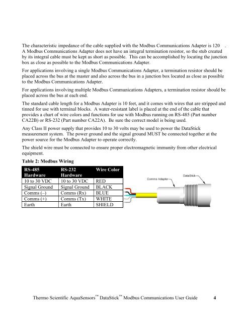
Table 2: <strong>Modbus</strong> Wiring<br />
RS-485 RS-232 Wire Color<br />
Hardware Hardware<br />
10 to 30 VDC 10 to 30 VDC RED<br />
Signal Ground Signal Ground BLACK<br />
Comms (–) Comms (Rx) BLUE<br />
Comms (+) Comms (Tx) WHITE<br />
Earth Earth SHIELD<br />
<strong>Thermo</strong> <strong>Scientific</strong> AquaSensors DataStick <strong>Modbus</strong> Communications User Guide 4