Thermo Scientific AquaSensors™ DataStick™ Modbus ...
Thermo Scientific AquaSensors™ DataStick™ Modbus ...
Thermo Scientific AquaSensors™ DataStick™ Modbus ...

Create successful ePaper yourself
Turn your PDF publications into a flip-book with our unique Google optimized e-Paper software.
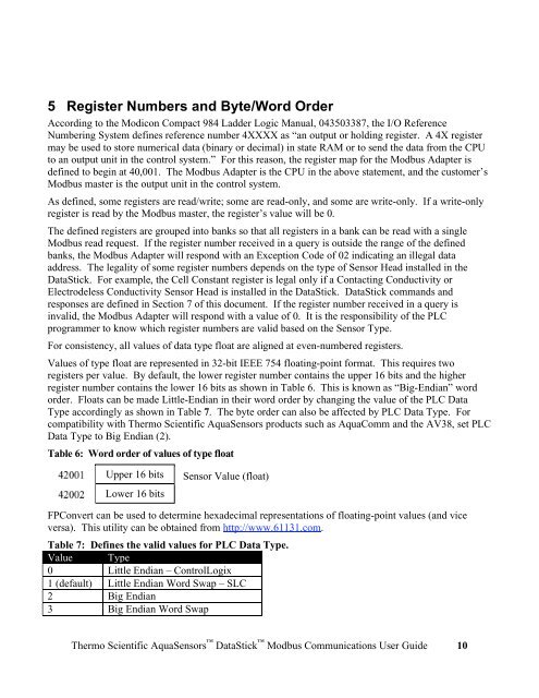
5 Register Numbers and Byte/Word Order<br />
According to the Modicon Compact 984 Ladder Logic Manual, 043503387, the I/O Reference<br />
Numbering System defines reference number 4XXXX as “an output or holding register. A 4X register<br />
may be used to store numerical data (binary or decimal) in state RAM or to send the data from the CPU<br />
to an output unit in the control system.” For this reason, the register map for the <strong>Modbus</strong> Adapter is<br />
defined to begin at 40,001. The <strong>Modbus</strong> Adapter is the CPU in the above statement, and the customer’s<br />
<strong>Modbus</strong> master is the output unit in the control system.<br />
As defined, some registers are read/write; some are read-only, and some are write-only. If a write-only<br />
register is read by the <strong>Modbus</strong> master, the register’s value will be 0.<br />
The defined registers are grouped into banks so that all registers in a bank can be read with a single<br />
<strong>Modbus</strong> read request. If the register number received in a query is outside the range of the defined<br />
banks, the <strong>Modbus</strong> Adapter will respond with an Exception Code of 02 indicating an illegal data<br />
address. The legality of some register numbers depends on the type of Sensor Head installed in the<br />
DataStick. For example, the Cell Constant register is legal only if a Contacting Conductivity or<br />
Electrodeless Conductivity Sensor Head is installed in the DataStick. DataStick commands and<br />
responses are defined in Section 7 of this document. If the register number received in a query is<br />
invalid, the <strong>Modbus</strong> Adapter will respond with a value of 0. It is the responsibility of the PLC<br />
programmer to know which register numbers are valid based on the Sensor Type.<br />
For consistency, all values of data type float are aligned at even-numbered registers.<br />
Values of type float are represented in 32-bit IEEE 754 floating-point format. This requires two<br />
registers per value. By default, the lower register number contains the upper 16 bits and the higher<br />
register number contains the lower 16 bits as shown in Table 6. This is known as “Big-Endian” word<br />
order. Floats can be made Little-Endian in their word order by changing the value of the PLC Data<br />
Type accordingly as shown in Table 7. The byte order can also be affected by PLC Data Type. For<br />
compatibility with <strong>Thermo</strong> <strong>Scientific</strong> AquaSensors products such as AquaComm and the AV38, set PLC<br />
Data Type to Big Endian (2).<br />
Table 6: Word order of values of type float<br />
42001<br />
42002<br />
Upper 16 bits<br />
Lower 16 bits<br />
Sensor Value (float)<br />
FPConvert can be used to determine hexadecimal representations of floating-point values (and vice<br />
versa). This utility can be obtained from http://www.61131.com.<br />
Table 7: Defines the valid values for PLC Data Type.<br />
Value Type<br />
0 Little Endian – ControlLogix<br />
1 (default) Little Endian Word Swap – SLC<br />
2 Big Endian<br />
3 Big Endian Word Swap<br />
<strong>Thermo</strong> <strong>Scientific</strong> AquaSensors DataStick <strong>Modbus</strong> Communications User Guide 10