CKD series SMD2 compact cylinders - BIBUS France
CKD series SMD2 compact cylinders - BIBUS France
CKD series SMD2 compact cylinders - BIBUS France
- No tags were found...

You also want an ePaper? Increase the reach of your titles
YUMPU automatically turns print PDFs into web optimized ePapers that Google loves.
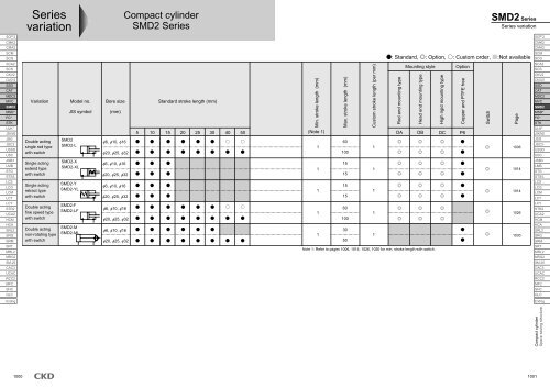
Variation and option selection tableCodeAccessory OptionPortthread VariationDouble acting basic typeSingle acting extend typeSingle acting retract typeNon-rotating typeWith cylinder switchFine speed typeNPTGCopper and PTFE free typeClean room specifications (exhaust treatment)Clean room specifications (vacuum treatment)Clean room specifications (exhaust treatment)Clean room specifications (vacuum treatment)Customized piston rod end formCylinder switchRod eyeRod clevisB1 bracketB2 bracketSymbolBlankYXMLFNGP6P7P71P72P73N**Listed onEndingIYB1B2: Option: Available (custom order): Available dipending on condition (consult with <strong>CKD</strong>)X: Not availableCode Variation Port thread OptionDouble acting basic typeSingle acting extend typeSingle acting retract typeNon-rotating typeWith cylinder switchFine speed typeNPTGCopper and PTFE free typeClean room specifications (exhaust treatment)Clean room specifications (vacuum treatment)Clean room specifications (exhaust treatment)Clean room specifications (vacuum treatment)Customized piston rod end formCautionsNote 1. If the size of the screw at the piston rod end is changed, this combination does not apply. Consult with <strong>CKD</strong>.Note 2. Refer to the "Clean Component System (catalog No. CB-033SA)" for clean room specifications P7*.Note 3. P6 specifications are available as standard. (Required no indication for P6 )Note 4: When combining the clean specifications with the nonrotating type, the guide bar will slide separately from the piston rod.There are dust generating sections other than the piston rod, so this will be handled with separate symbols (P72 (exhaust treatment) and P73 (vacuum sweep)).<strong>SMD2</strong> M L F DA 16 20 K0H DABCDEFGHModel no.VariationIndicate symbols from leftto right on the left table.Model no.: Compact cylinderA Mountingstyle B BoresizeNo X YD StrokelengthC Port threadtypeVariation: Non-rotating with switch fine speed typeMounting style : Rod end mounting typeBore size : 16 mmPort thread type : Rc threadStroke length : 20 mmSwitch model no. : Reed K0H switch, lead wire 1 mSwitch quantity : 2Option: NoneAccessory : NoneXM LFXXN G P6 P7 P71Note 3Note 3 XNote 3 XXE Switchmodel no.Note 3Note 3XNote 3Note 3XXNote 4XXXXXF SwitchquantityNote 4XXXXXXP72XXXXXXXXXXHP73XXXXXXXXXXXN**Note 1Note 1AccessoryG OptionIndicate symbols from leftto right on the left table.<strong>SMD2</strong> SeriesVariation and option selection table1003SCP*2CMK2CMA2SCMSCGSCA2SCSCKV2CA/OV2SSDCATMDC2MVC<strong>SMD2</strong>MSD*FC*STKULK*JSK/M2JSGJSC3USSDUSCJSB3LMBSTGSTS/LLCSLCGLCMLCTLCYSTR2UCA2HCMHCASRL2SRGSRMSRTMRL2MRG2SM-25CAC3UCACRCC2MFCSHCGLCEndingCompact cylinderSpace saving structure
SCP*2CMK2CMA2SCMSCGSCA2SCSCKV2CA/OV2SSDCATMDC2MVC<strong>SMD2</strong>MSD*FC*STKULK*JSK/M2JSGJSC3USSDUSCJSB3LMBSTGSTS/LLCSLCGLCMLCTLCYSTR2UCA2HCMHCASRL2SRGSRMSRTMRL2MRG2SM-25CAC3UCACRCC2MFCSHCGLCEndingPneumatic componentsSafety precautionsAlways read this section before starting use.Refer to Intro 71 for general details on the cylinder, and to Intro 78 for details on the cylinder.Compact cylinder <strong>SMD2</strong> Series1. Fine speed type <strong>SMD2</strong>-FCAUTIONUse with oil-free specifications.Lubrication may change characteristics.Assemble the flow control valve near the cylinder.Adjustments become unstable if assembled away from the cylinder.Use the SC-M3/M5, SC3W, SCD-M3/M5, SC3WU Seriesspeed control valve.Generally, the higher air pressure, and the smallerload pressure result in the more stable operation.Keep the load factor at 50% or less.Stable speed control is achieved with a meter-outcircuit.When driving the single rod cylinder at fine speed with theoperation direction set to PUSH, popping-out may occur if operationis started when load resistance is small. As a countermeasure,use (b), (c), or (d) circuit.Note that the (d) circuit isthe most stable.acPUSH: meter-outPULL: meter-outPUSH: meter-inPULL: meter-outbdPUSH: meter-inPULL: meter-inPUSH: meter-in/outPULL: meter-outDesign & Selection(Note 2) When installed vertically, the load will drop naturally if themeter-in circuit is used. Use the meter-out circuit in this case.Speed controlis unstableDrops naturallywhen lowering(Note 3) Connect the peed control valve in the parallel with the followingcircuit.(Cause of popping out)Reduce the flow rate to reach a fine speed at the exhaustside in a mater-out circuit. This results in the samepressure level on the both sides immediately after valveswitched. The thrust caused by the differential of pressurizedarea of piston is applied to the PUSH direction and apopping-out of piston rod occurs.(Guide for popping out occurrence)Popping out occurs when: the piston rod area x airpressure> load resistance.Do not apply lateral load a cylinder.Install the cylinder to avoid the sliding guide to betwisted.The presence of load or resistance variation may result in unstableoperations.Operation of a guide having a large difference in stationaryand moving friction may become unstable.d Speed adjustment method of PUSH operation of circuit:1. Set the speed with the x speed control valve2. Lower the flow rate with the y speed control valve until popping out no longer occurs3. Reconfirm speedAvoid use with vibration.The product would be adversely affected by vibration and operationmay become unstable.(Note 1) When b, c and d are compared, d circuit operation is most stable.1004
<strong>SMD2</strong> Series2 <strong>cylinders</strong> in parallel3 or more <strong>cylinders</strong> in parallel1. CommonCAUTIONThe cylinder may malfunction if a magnetic substance,such as a steel plate, is nearby. Move the magneticsubstance to at least 3.5mm from the cylinder.(Same clearance for all bore sizes)When installing <strong>cylinders</strong> adjacently, provide the followinginstallation pitch to prevent switches from malfunctioning.Adjacent conditions· Horizontalinstallation· Vertical installationInstall the switchon the oppositeside of the cylinderat the side.· Vertical installationInstall switch atside of adjacentcylinder.· Horizontalinstallation· Verticalinstallation2. Single acting <strong>SMD2</strong>-X/YCAUTIONABABABABAABABBSwitchABABABABABSwitchmodel no.K0, K5K2, K3K0, K5K2, K3K0, K5K2, K3K0, K5K2, K3K0, K5K2, K3K0, K5K2, K3K0, K5K2, K3K0, K5K2, K3K0, K5K2, K3K0, K5K2, K3Do not leave the single acting cylinder in the pressurizedstate.If left pressurized, the piston rod may not return with springpower when pressure is released.Installation & Adjustment6 10 16 20 25 3227 29 3718255.511.521285.512.525355.514.514 16 2127 29 3719276.513.522296.513.526356.514.54.50.54.545 55 6733406.514.541508.517.546555.514.527 33 4145 55 6734447.517.542519.518.53.5mm and over47566.515.53. Fine speed type <strong>SMD2</strong>-FMagnetized device suchas steel plate, etc.RemarksUnit: mmNote that when the cylinder isinstalled, the switch positioncannot be adjusted if thedriver length is longer than theB dimension.Note that when the cylinder isinstalled, the switch positioncannot be adjusted if thedriver length is longer thanthe B dimension.CAUTIONAdjust the core, etc., so lateral load is not applied tothe cylinder.Adjust and install so the sliding guide is not twisted.Operation may become unstable due to fluctuations andload resistance.Operation of a guide having a large difference in stationaryand moving friction may become unstable.SCP*2CMK2CMA2SCMSCGSCA2SCSCKV2CA/OV2SSDCATMDC2MVC<strong>SMD2</strong>MSD*FC*STKULK*JSK/M2JSGJSC3USSDUSCJSB3LMBSTGSTS/LLCSLCGLCMLCTLCYSTR2UCA2HCMHCASRL2SRGSRMSRTMRL2MRG2SM-25CAC3UCACRCC2MFCSHCGLCEnding1. Non-rotating type <strong>SMD2</strong>-MCAUTIONDo not place fingers between the baffle non-rotatingplate and cylinder tube.Fingers may get caught between the non-rotating plate andcylinder tube when the piston rod is pulled in. Do not placefingers here.During Use & Maintenance1005Compact cylinderSpace saving structure
SCP*2CMK2CMA2SCMSCGSCA2SCSCKV2CA/OV2SSDCATMDC2MVC<strong>SMD2</strong>MSD*FC*STKULK*JSK/M2JSGJSC3USSDUSCJSB3LMBSTGSTS/LLCSLCGLCMLCTLCYSTR2UCA2HCMHCASRL2SRGSRMSRTMRL2MRG2SM-25CAC3UCACRCC2MFCSHCGLCEndingSpecificationsDescriptionsBore size mmActuationWorking fluidMax. working pressure MPaMin. working pressure MPaWithstanding pressure MPaAmbient temperaturePort sizeStroke toleranceWorking piston speed mm/sCushionLubricationAllowable energy absorption JStroke lengthBore size (mm)61016202532<strong>SMD2</strong><strong>SMD2</strong>-L (with switch)6 10 16 20 25 32Double actingCompressed air0.70.150.11.05-10 to 60 (no freezing)M5Rc1/8+1.5050 to 500Rubber cushionedNot required (when lubricating, use turbine oil Class 1 ISO VG32.)0.005 0.036 0.1 0.1 0.19 0.5Standard stroke length (mm)5, 10, 15, 20, 25, 305, 10, 15, 20, 25, 30, 40, 50Min. stroke length with switchModel<strong>SMD2</strong>-L-DA<strong>SMD2</strong>-L-DB/DCmmNote 1: Custom stroke length is available per 1mm increment.Bore size6101620253261016202532Compact cylinder, double acting single rod type<strong>SMD2</strong> SeriesBore size: 6, 10, 16, 20, 25, 32JIS symbolMax. stroke length (mm)60100Double actingMin. stroke length (mm)11 color indicator type 2 color indicator type With preventive maintenance outputK*H K*V K*YH K*YV K*Y*H K*Y*V5 5 115 15 10 1010 15 10 1010 5 10 10 1010 10 5 55 5 5 55 5 5 51006
Switch specifications1 color/2 color indicatorProximity 2-wireProximity 3-wireReed 2-wireDescriptionsK2H/K2V K2YH/K2YV K3H/K3V K3PH/K3PV K3YH/K3YV(Custom order)K0H/K0VK5H/K5VApplicationsOutput methodProgrammable controller-Programmable controller, relayNPN output PNP output NPN output-Programmable Programmable controller, relaycontroller, relayIC circuit (w/o indicator light), serial connectionPower voltage-10 to 28 VDC-Load voltageLoad current10 to 30 VDC5 to 20mA (Note 1)30 VDC or less50mA or less12 VDC /24 VDC5 to 50mA110 VAC7 to 20mA5/12/24 VDC50mA or less110 VAC20mA or lessLightLED (ON lighting) Red/green LED (ON lighting) LED (ON lighting) Yellow LED (ON lighting) Red/green LED (ON lighting) LED (ON lighting)-Leakage current1mA or less10 A or less0mANote 1: Max. load current above: 20 mA at 25 . The current will be lower than 20 mA if ambient temperature around switch is higher than 25 . (5 to 10mA at 60 )With preventive maintenance outputDescriptionsProximity 3-wire Proximity 4-wire Proximity 3-wire Proximity 4-wireK2YFH/V K3YFH/V K2YMH/V K3YMH/VApplicationsOutput methodInstallation position adjustmentProgrammable controllerProgrammableProgrammableProgrammable controllercontroller, relaycontroller, relayNPN outputRed/green LED (ON lighting)Preventive maintenance output-Yellow LED (ON lighting)Power voltageLoad voltageLoad currentLeakage currentLoad voltage-10 to 30 VDC5 to 20mA1mA or less10 to 28 VDC30 VDC or less50mA or less10 A or less30 VDC or less-10 to 30 VDC5 to 20mA1.2mA or less10 to 28 VDC30 VDC or less50mA or less10 A or lessLoad currentLeakage current20mA or less50mA or less5 to 20mA or less10 A or less50mA or lessLightOutputPreventivemaintenanceoutputCylinder weightModel no.Bore size SupporttypeDA6 DBDCDA10 DBDCDA16 DBDCDA20 DBDCDA25 DBDCDA32 DBDCProduct weight when stroke length S = 0mm<strong>SMD2</strong>Double acting262534373648706897137131178229220291445427574Clean room specifications<strong>SMD2</strong><strong>SMD2</strong><strong>SMD2</strong>-LDouble acting/with switch2625343736488784113166160207275265337515497644346111726Unit (g)Additionalweight perS = 5mm(Catalog No. CB-033SA)Dust generation preventing structure for use in clean roomP7*P5*Discrete cylinder switch weightNameCylinder switch(Example) Product weight<strong>SMD2</strong>-L-DA-16-10-K2-DModel no.K0K2K3K51m18181818<strong>SMD2</strong> SeriesSpecificationsLead wire length3m52525252Unit (g)5m86868686Product weight at stroke length = 0mm ··· 87gAdditional weight when S=10mm ··· 6g x 10/5 = 12gWeigh of two cylinder switches ··· 18g x 2 = 36gProduct weight ··· 87g + 12g + 36g = 135gSCP*2CMK2CMA2SCMSCGSCA2SCSCKV2CA/OV2SSDCATMDC2MVC<strong>SMD2</strong>MSD*FC*STKULK*JSK/M2JSGJSC3USSDUSCJSB3LMBSTGSTS/LLCSLCGLCMLCTLCYSTR2UCA2HCMHCASRL2SRGSRMSRTMRL2MRG2SM-25CAC3UCACRCC2MFCSHCGLCEndingCompact cylinderSpace saving structure1007
<strong>SMD2</strong> SeriesSCP*2CMK2CMA2SCMSCGSCA2SCSCKV2CA/OV2SSDCATMDC2MVC<strong>SMD2</strong>MSD*FC*STKULK*JSK/M2JSGJSC3USSDUSCJSB3LMBSTGSTS/LLCSLCGLCMLCTLCYSTR2UCA2HCMHCASRL2SRGSRMSRTMRL2MRG2SM-25CAC3UCACRCC2MFCSHCGLCEndingHow to orderWithout switch<strong>SMD2</strong>With switch<strong>SMD2</strong>-LDA6<strong>SMD2</strong>-L-DA-6-15-K0H-R15 K2H RC Port thread typeNote on model no. selectionBoresize61016202532DA615D Stroke lengthDB (head end mounting type) DC (high rigid mounting type)5 mm stroke 10 mm stroke 5 mm stroke 10 mm strokeXXXXX XXXXXModel: Compact cylinderA Mounting style : Rod end mounting typeB Bore size : 6mmC Port thread type : Rc threadD Stroke length : 15mmE Switch model no. : Reed switch K0H, lead wire length 1mF Switch quantity : 1 on rod endHow to order switchSW K2HAMountingstyleB Bore sizeNote 1: For mounting style "DB" or "DC", if "X" indicated on"Switch selection table", K* H type (axial lead wire) cannotbe installed. Please use K*V type (radial lead wire).Switch selection tableNote 2: Refer to page 1006 for min. stroke length with switch.Note 3: Copper and PTFE free as standard.E Switch model no.Note 1F SwitchquantitySymbolDescriptionsA Mounting styleDA Rod end mounting typeDB Head end mounting typeDC High rigid mounting typeB Bore size (mm)C6101620253232) custom orderG thread (only 32) custom orderD Stroke length (mm)Bore size Stroke length Note 2 Custom stroke length6 to 16 1 to 60By 1 mm increment20 to 32 1 to 100Switch model no.EAxial leadwireK0H*K5H*K2H*K3H*K3PH*K2YH*K3YH*K2YFH*K3YFH*K2YMH*K3YMH*K0V*K5V*K2V*K3V*K3PV*K2YV*K3YV*K2YFV*K3YFV*K2YMV*K3YMV**Lead wire lengthBlank3561016202532Port thread typeBlankNNGNRc threadNPT thread (onlyRadial leadwire1m (standard)3m (option)5m (option)F Switch quantityR 1 on rod endH 1 on head endD TwoContact Indicator Lead wireReedProximity1 color indicator typeWithout indicator light1 color indicator type1 color indicator type (custom order)2 color indicator type2 color indicator type(W/o indicator light for preventivemaintenance output)2 color indicator type(W/ indicator light for preventivemaintenance output (1 color))2-wire2-wire3-wire3-wire2-wire3-wire3-wire4-wire3-wire4-wireSwitch model no.(Item E above)1008
Internal structure and parts listDouble acting/with switch, magnet built-in type <strong>SMD2</strong>-L6, 1016, 20, 25, 32Double acting <strong>SMD2</strong>6, 10 16, 20, 25, 321 18 2 3 4 5 6 7 10 8 9No.12Parts namePiston rodCapMaterialStainless steelAluminum alloy3 Rod packing seal Nitrile rubber456Rod bushingCylinder bodyGasketAluminum alloyAluminum alloyNitrile rubber7 Cushion rubber (R) Urethane rubber8 Piston Aluminum alloy9 Piston packing seal Nitrile rubberRepair parts listBore size (mm)610161 18 2 3 4 5 6 7 10 8 91 18 3 4 5 6 7 10 8 91616 171517Kit No.<strong>SMD2</strong>-6K<strong>SMD2</strong>-10K<strong>SMD2</strong>-16K11 1211 121313 1416 1715 11 12 1314RemarksNo.20, 25, 32 industrial chrome plating 101112Alumite13Hard alumite14151617181 18 3 4 5 6 7 8 9Parts nameSpacerMaterialAluminum alloyCushion rubber (H) Urethane rubberBase plate Aluminum alloyGasket Nitrile rubberC type snap ring SteelMagnet PlasticMount Aluminum alloyHexagon socket head cap bolt Alloy steelHexagon nut SteelRemarksChromatePhosphoric acid zincBlack alumiteBlackeningNickelingRepair parts numberBore size (mm) Kit No.Repair parts number20 <strong>SMD2</strong>-20K3 7 9 11 13 25 <strong>SMD2</strong>-25K3 7 9 11 1332 <strong>SMD2</strong>-32K1617<strong>SMD2</strong> SeriesDouble acting single rod type11 12131414SCP*2CMK2CMA2SCMSCGSCA2SCSCKV2CA/OV2SSDCATMDC2MVC<strong>SMD2</strong>MSD*FC*STKULK*JSK/M2JSGJSC3USSDUSCJSB3LMBSTGSTS/LLCSLCGLCMLCTLCYSTR2UCA2HCMHCASRL2SRGSRMSRTMRL2MRG2SM-25CAC3UCACRCC2MFCSHCGLCEndingCompact cylinderSpace saving structure1009
<strong>SMD2</strong> SeriesSCP*2CMK2CMA2SCMSCGSCA2SCSCKV2CA/OV2SSDCATMDC2MVC<strong>SMD2</strong>MSD*FC*STKULK*JSK/M2JSGJSC3USSDUSCJSB3LMBSTGSTS/LLCSLCGLCMLCTLCYSTR2UCA2HCMHCASRL2SRGSRMSRTMRL2MRG2SM-25CAC3UCACRCC2MFCSHCGLCEndingDimensionsDouble acting/with switch, rod end mounting type <strong>SMD2</strong>-(L)-DA6, 1016, 20, 25, 32GSymbolBore size (mm)61016202532SymbolBore size (mm)61016202532VFGAVKKWidth across flats BVVBFCVVDWEESKKWidth across flats BSWFTMNTCAGCMMXFXFMMHNNQQNQHHJ--12.55.57871011101010M5M5M513.4 22.415.4 24.420.4 32.4111110M2.5 depth 5M3 depth 5M4 depth 63.4 (penetrating) 5.9 spot face depth 5.33.4 (penetrating) 5.9 spot face depth 5.54.5 (penetrating) 7.5 spot face depth 7M3M4M5346--5777111115--579121.82.43.217182413.5 1017.5 131215.51010M5M526.4 40.432.4 50.41414M5 depth 8M5 depth 85.5 (penetrating) 9 spot face depth 8.55.5 (penetrating) 9 spot face depth 9.5M6M8810689101515121316203.65303821 17 19.5 11 Rc1/8 40.4 62.4 21 M6 depth 9 6.6 (penetrating) 10.5 spot face depth 12 M10 x 1.25 12 10 11 20 17 24 6 48LL X With switchV VV W XF W/o W/ W/o W/K0H/K5H K2H/K3H K0V/K5V K2V/K3VEswitch switch switch switch HD RD HD RD HD RD HD RD6.7 11.2 10 13 38 38 51 51 1.0 -2.0 5.0 -3.0 6.0 -5.0 5.0 -6.0 6.07.7 12.2 11 16 41 41 57 57 1.0 0.5 5.5 -1.0 7.0 -2.5 5.5 -4.0 7.010.2 16.2 14 16 40 50 56 66 0.5 1.5 10.0 0.5 11.0 -1.5 10.0 -2.5 11.013.2 20.2 16 19 46 56 65 75 0.5 5.5 12.5 4.5 13.5 2.5 12.5 1.5 13.516.2 25.2 20 23 50 60 73 83 0.5 8.5 12.5 7.5 13.5 5.5 12.5 4.5 13.520.2 31.2 24 27 62 72 89 99 0.5 9.0 19.0 8.0 20.0 6.0 19.0 5.0 20.0KAKKMM MNNote 1: HD and RD dimensions for 5, 10 stroke will differ from these due to manufacturing.Note 2: Negative dimension shows dimensions of projecting section of switch from main body.Note 3: Refer to page 1036 for HD, RD and dimensions of projecting section of 2 color indicator type preventive maintenance output switch.2-JH2-J4-KA2-EENQ RDLL + stroke lengthX + stroke lengthHRD2-J2-J4-KA2-EELL + stroke lengthX + stroke lengthDDEHDREHD2-HHUN2-HHQURSTU1010
DimensionsDouble acting/with switch, head end mounting type <strong>SMD2</strong>-(L)-DB6, 10SymbolBore size (mm)61016202532SymbolBore size (mm)6101620253216, 20, 25, 32U2-HHAB2-HHUKKWidth across flats BCDEEKKWidth across flats BFGHHHJKAKK<strong>SMD2</strong> SeriesDouble acting single rod typeMM MN MP- 5.5 7 10 M5 13.4 22.4 11 M2.5 depth 5 3.4 (penetrating) 5.9 spot face depth 5.3 M3 3 - 5 7 11 - 7 1.8 17-12.513.517.578101310111215.510101010M5M5M5M515.4 24.420.4 32.426.4 40.432.4 50.411101414M3 depth 5M4 depth 6M5 depth 8M5 depth 83.4 (penetrating)4.5 (penetrating)5.5 (penetrating)5.5 (penetrating)5.9 spot face depth 5.57.5 spot face depth 79 spot face depth 8.59 spot face depth 9.5M4M5M6M846810-5686812147791011151515-5121391216202.43.23.651824303821 17 19.5 11 Rc1/8 40.4 62.4 21 M6 depth 9 6.6 (penetrating) 10.5 spot face depth 12 M10 x 1.25 12 10 16 11 20 17 24 6 48LL X With switchV VV W XF Y W/o W/ W/o W/K0H/K5H K2H/K3H K0V/K5V K2V/K3VEswitch switch switch switch HD RD HD RD HD RD HD RD6.7 11.2 10 14 1 38 38 52 52 1.0 1.5 5.0 2.5 6.0 1.5 5.0 2.5 6.07.7 12.2 11 17 1 41 41 58 58 1.0 3.5 5.5 4.5 7.0 3.5 5.5 4.5 7.010.2 16.2 14 16 1 40 50 56 66 0.5 5.0 10.0 6.0 11.0 5.0 10.0 6.0 11.013.2 20.2 16 19 1.5 46 56 65 75 0.5 8.5 12.5 9.5 13.5 8.5 12.5 9.5 13.516.2 25.2 20 23 2 50 60 73 83 0.5 11.5 12.5 12.5 13.5 11.5 12.5 12.5 13.520.2 31.2 24 27 2 62 72 89 99 0.5 12.0 19.0 13.5 20.0 12.0 19.0 13.5 20.0Note 1: HD and RD dimensions for 5, 10 stroke will differ from these due to manufacturing.Note 2: Negative dimension indicates dimensions of projecting section of switch from main body.Note 3: For 5, 10 mm stroke <strong>cylinders</strong>, use K*V switch because K*H switch cannot be installed.Note 4: For 5 mm stroke cylinder, use K*V switch because K*H switch cannot be installed.TMNMP 0-0.1TCAECXFMMXFMP -0.10MMHRDYHRD2-EE 2-JDLL + stroke lengthX + stroke lengthHDNQQSWN2-J4-KA2-EE 2-JLL + stroke lengthX + stroke lengthDHDQQNNRE2-JWS4-KAGGVFNote 5: Refer to page 1037 for HD/RD and dimensions of projectingsection of 2 color indicator type preventive maintenanceoutput switch.VNVVFQVVRSTU1011SCP*2CMK2CMA2SCMSCGSCA2SCSCKV2CA/OV2SSDCATMDC2MVC<strong>SMD2</strong>MSD*FC*STKULK*JSK/M2JSGJSC3USSDUSCJSB3LMBSTGSTS/LLCSLCGLCMLCTLCYSTR2UCA2HCMHCASRL2SRGSRMSRTMRL2MRG2SM-25CAC3UCACRCC2MFCSHCGLCEndingCompact cylinderSpace saving structure
<strong>SMD2</strong> SeriesSCP*2CMK2CMA2SCMSCGSCA2SCSCKV2CA/OV2SSDCATMDC2MVC<strong>SMD2</strong>MSD*FC*STKULK*JSK/M2JSGJSC3USSDUSCJSB3LMBSTGSTS/LLCSLCGLCMLCTLCYSTR2UCA2HCMHCASRL2SRGSRMSRTMRL2MRG2SM-25CAC3UCACRCC2MFCSHCGLCEnding1012DimensionsDouble acting/with switch, high rigid mounting type <strong>SMD2</strong>-(L)-DC6, 10SymbolBore size (mm)61016202532SymbolBore size (mm)16, 20, 25, 32G61016202532VAFBVVCDGVEEFVVKKWidth across flats BWidth across flats BFGHHHJKAKKMM MN- 5.5 7 10 M5 13.4 22.4 11 M2.5 depth 5 3.4 (penetrating) 5.9 spot face depth 5.3 M3 3 - 7 11 - 7 1.8 17- 7 10 10 M5 15.4 24.4 11 M3 depth 5 3.4 (penetrating) 5.9 spot face depth 5.5 M4 4 - 7 11 - 9 2.4 1812.5 8 11 10 M5 20.4 32.4 10 M4 depth 6 4.5 (penetrating) 7.5 spot face depth 7 M5 6 5 7 15 5 12 3.2 2413.5 10 12 10 M5 26.4 40.4 14 M5 depth 8 5.5 (penetrating) 9 spot face depth 8.5 M6 8 6 9 15 12 16 3.6 3017.5 13 15.5 10 M5 32.4 50.4 14 M5 depth 8 5.5 (penetrating) 9 spot face depth 9.5 M8 10 8 10 15 13 20 5 3821 17 19.5 11 Rc1/8 40.4 62.4 21 M6 depth 9 6.6 (penetrating) 10.5 spot face depth 12 M10 x 1.25 12 10 11 20 17 24 6 48LL X With switchV VV W XF W/o W/ W/o W/K0H/K5H K2H/K3H K0V/K5V K2V/K3VEswitch switch switch switch HD RD HD RD HD RD HD RD6.7 11.27.7 12.210.2 16.213.2 20.216.2 25.21011141620131616192349525561654952657175626871808862688190981.01.00.50.50.51.53.55.08.511.55.05.510.012.512.52.54.56.09.512.56.07.011.013.513.51.53.55.08.511.55.05.510.012.512.52.54.56.09.512.56.07.011.013.513.520.2 31.2 24 27 82 92 109 119 0.5 12.0 19.0 13.5 20.0 12.0 19.0 13.5 20.0Note 1: HD and RD dimensions for 5, 10 stroke will differ from these due to manufacturing.Note 2: Negative dimension indicates dimensions of projecting section of switch from main body.Note 3: For 5, 10 mm stroke <strong>cylinders</strong>, use K*V switch because K*H switch cannot be installed.Note 4: For 5 mm stroke cylinder, use K*V switch because K*H switch cannot be installed.SWKKSWTCAMNXFMMTCXFNNNMMQQYQNQ2-JHRD2-J4-KA2-J2-EE 2-JH D Q2-J4-KAEHDRDLL + stroke lengthX + stroke lengthQSNWN2-EE 2-JLL + stroke lengthX + stroke lengthHDDPQNN2-J4-KARE2-JWS4-KANote 5: Refer to page 1038 for HD/RD and dimensions of projectingsection of 2 color indicator type preventive maintenanceoutput switch.NQRSTU
SCP*2CMK2CMA2SCMSCGSCA2SCSCKV2CA/OV2SSDCATMDC2MVC<strong>SMD2</strong>MSD*FC*STKULK*JSK/M2JSGJSC3USSDUSCJSB3LMBSTGSTS/LLCSLCGLCMLCTLCYSTR2UCA2HCMHCASRL2SRGSRMSRTMRL2MRG2SM-25CAC3UCACRCC2MFCSHCGLCEndingSpecificationsDescriptionsBore sizeActuationmm<strong>SMD2</strong>-X (L)<strong>SMD2</strong>-Y (L)Working fluidMax. working pressure MPaMin. workingpressureMPa <strong>SMD2</strong>-X (L)<strong>SMD2</strong>-Y (L)Withstanding pressure MPaAmbient temperaturePort sizeStroke toleranceWorking piston speedCushionmmmm/s<strong>SMD2</strong>-X (L)<strong>SMD2</strong>-Y (L)LubricationAllowable energy absorption JStroke lengthBore size (mm)61016202532Model<strong>SMD2</strong>-XL-DA<strong>SMD2</strong>-YL-DA<strong>SMD2</strong>-XL-DB/DC<strong>SMD2</strong>-YL-DB/DCBore size61016202532610162025326101620253260.30.35<strong>SMD2</strong>-X, <strong>SMD2</strong>-Y<strong>SMD2</strong>-XL, <strong>SMD2</strong>-YL (with switch)10 16 20 25Single acting, extend typeSingle acting, retract typeCompressed air0.71 color indicator type 2 color indicator type With preventive maintenance outputK*H K*V K*YH K*YV K*Y*H K*Y*V15101010551010555550.21.05-10 to 60 (no freezing)M5Rc1/8+1.5050 to 500Rubber cushioned at only retract sideRubber cushioned at only extend sideNot required (when lubricating, use turbine oil Class 1 ISO VG32.)0.005 0.036Note: Do not leave the single acting cylinder in the pressurized state. If left in the pressurized state, the pistonrod may not return with spring force when pressure is released.0.1550.1Standard stroke length (mm) Max. stroke length (mm)5, 10, 15Note 1: Custom stroke length is available per 1mm increment.Min. stroke length with switchCompact cylinder,<strong>SMD2</strong>- X Y SeriesBore size: 6, 10, 16, 20, 25, 32JIS symbolSingle acting, extend typesingle acting extend type/with switchsingle acting retract type/with switch0.1915 1151510105510105555Single acting, retract type320.150.5Min. stroke length (mm)5 51010105551010555510101055510555551014
Switch specifications1 color/2 color indicator<strong>SMD2</strong>- X Y cylinder weight(Weight with switch is with a 2 piece by cylinder switch lead wire length 1m.) Unit (g)Stroke length (mm) 5 10 15Bore size (mm) Supporttype W/o switch With switch W/o switch With switch W/o switch With switch61016202532DADBDCDADBDCDADBDCDADBDCDADBDCDADBDC333241464557858311216415820527326433551249464169687782819313813512822922327035534541761860074736354450496191891181751692162902813525386206671051041131181171291741711642652593063913814536546367833938475453659795124186180227307298369564546693141140149154153165210207200301295342427417489690672819<strong>SMD2</strong>-X/<strong>SMD2</strong>-Y spring loadBore size(mm)61016Stroke length(mm)510155101551015Stroke length03.422.832.256.135.033.9212.69.997.35Full stroke lengthduring operation4.027.2515.3Bore size(mm)202532Stroke length(mm)510155101551015Discrete cylinder switch weightCylinder switchStroke length013.711.79.733.328.724.034.429.424.5NameUnit: NFull stroke lengthduring operation15.838.039.5Model no.K0K2K3K51m18181818X<strong>SMD2</strong>- Y SeriesSpecificationsProximity 2-wireProximity 3-wireReed 2-wireDescriptionsK2H/K2V K2YH/K2YV K3H/K3V K3PH/K3PV K3YH/K3YV(Custom order)K0H/K0VK5H/K5VApplicationsOutput methodProgrammable controller-Programmable controller, relayNPN output PNP output NPN output-Programmable Programmable controller, relaycontroller, relayIC circuit (without indicator light), serial connectionPower voltage-10 to 28 VDC-Load voltage10 to 30 VDC30 VDC or less12 VDC /24 VDC 110 VAC 5/12/24 VDC 110 VACLoad current5 to 20mA (Note 1)50mA or less5 to 50mA 7 to 20mA 50mA or less 20mA or lessLightLED (ON lighting) Red/green LED (ON lighting) LED (ON lighting) Yellow LED (ON lighting) Red/green LED (ON lighting) LED (ON lighting)-Leakage current1mA or less10 A or less0mANote 1: Max. load current above: 20 mA at 25 . The current will be lower than 20 mA if ambient temperature around switch is higher than 25 . (5 to 10mA at 60 )With preventive maintenance outputDescriptionsProximity 3-wire Proximity 4-wire Proximity 3-wire Proximity 4-wireK2YFH/V K3YFH/V K2YMH/V K3YMH/VApplicationsOutput methodInstallation position adjustment sectionProgrammable controllerProgrammableProgrammableProgrammable controllercontroller, relaycontroller, relayNPN outputRed/green LED (ON lighting)Preventive maintenance output-Yellow LED (ON lighting)Power voltageLoad voltageLoad currentLeakage currentLoad voltage-10 to 30 VDC5 to 20mA1mA or less10 to 28 VDC30 VDC or less50mA or less10 A or less30 VDC or less-10 to 30 VDC5 to 20mA1.2mA or less10 to 28 VDC30 VDC or less50mA or less10 A or lessLoad currentLeakage current20mA or less50mA or less5 to 20mA or less10 A or less50mA or lessLightOutputPreventivemaintenanceoutputLead wire length3m52525252Unit (g)5m868686861015SCP*2CMK2CMA2SCMSCGSCA2SCSCKV2CA/OV2SSDCATMDC2MVC<strong>SMD2</strong>MSD*FC*STKULK*JSK/M2JSGJSC3USSDUSCJSB3LMBSTGSTS/LLCSLCGLCMLCTLCYSTR2UCA2HCMHCASRL2SRGSRMSRTMRL2MRG2SM-25CAC3UCACRCC2MFCSHCGLCEndingCompact cylinderSpace saving structure
X<strong>SMD2</strong>- Y SeriesSCP*2CMK2CMA2SCMSCGSCA2SCSCKV2CA/OV2SSDCATMDC2MVC<strong>SMD2</strong>MSD*FC*STKULK*JSK/M2JSGJSC3USSDUSCJSB3LMBSTGSTS/LLCSLCGLCMLCTLCYSTR2UCA2HCMHCASRL2SRGSRMSRTMRL2MRG2SM-25CAC3UCACRCC2MFCSHCGLCEndingHow to orderWithout switch<strong>SMD2</strong>-XWith switch<strong>SMD2</strong>-XLBoresize610162025AModel no.DADABNote on model no. selectionDB (head end mounting type)5 mm stroke 10 mm strokeX XXXX66Mounting styleC Bore size15DC (high rigid mounting type)5 mm stroke 10 mm strokeXXXXX32<strong>SMD2</strong>-YL (single acting retract type)Bore DB (head end mounting type) DC (high rigid mounting type)size 5 mm stroke 10 mm stroke 5 mm stroke 10 mm stroke61016202532XXXX15 K2H RD Port thread typeE Stroke lengthNote 1: For mounting style "DB" or "DC", if "X" indicated on"Switch selection table", K* H type (axial lead wire)cannot be installed. Please use K*V type (radiallead wire).Switch selection table<strong>SMD2</strong>-XL (single acting extend type with switch)Note 2: Refer to page 1014 for min. stroke length with switch.Note 3: Copper and PTFE free as standard.F Switch model no.Note 1GSwitchquantitySymbolDescriptionsA Model no.<strong>SMD2</strong>-X Single acting extend type<strong>SMD2</strong>-Y Single acting retract typeB Mounting styleDADBDCRod end mounting typeHead end mounting typeHigh rigid mounting typeC Bore size (mm)6 610 1016 1620 2025 2532 32D Port thread typeBlankNNGNE Stroke length (mm)Bore size Stroke length Note 26 to 32 1 to 15F Switch model no.Axial lead Radial leadwire wireContactK0H* K0V*K5H* K5V*K2H* K2V*K3H* K3V*K3PH* K3PV*K2YH* K2YV*K3YH* K3YV*K2YFH* K2YFV*K3YFH* K3YFV*K2YMH* K2YMV*K3YMH* K3YMV**Lead wire lengthBlank 1m (standard)3 3m (option)5 5m (option)G Switch quantityRHDRc threadNPT thread (only 32) custom orderG thread (only 32) custom order1 on rod end1 on head endTwoReedProximityProximityCustom stroke length1 mm incrementIndicator1 color indicator typeWithout indicator light1 color indicator type1 color indicator type (custom order)2 color indicator type2 color indicator type(W/o indicator light forpreventive maintenance output)2 color indicator type(W/ indicator light for preventivemaintenance output (1 color))Lead wire2-wire2-wire3-wire3-wire2-wire3-wire3-wire4-wire3-wire4-wireFG1016<strong>SMD2</strong>-XL-DA-6-15-K0H-RModel: Compact cylinderABCDEModel no.Mounting style: Single acting extend type: Rod end mounting typeBore size : 6mmPort thread type : Rc threadStroke length : 15mmSwitch model no. : Reed switch K0H, lead wire length 1mSwitch quantity : 1 on rod endHow to order switchSW K2HSwitch model no.(Item F above)
<strong>SMD2</strong>-X SeriesInternal structure and parts listInternal structure and parts listSingle acting extend type/with switch, magnet built-in type <strong>SMD2</strong>-XL6, 1016, 20, 25, 32Single acting extend type <strong>SMD2</strong>-X6, 10 16, 20, 25, 32No. Parts name1 Hexagon nut2 Rod bushing3 Cylinder body4 Spring5 Piston rod6781 2 3 4Spring holderSpacerMagnetRepair parts listBore size (mm)6101615161 2 3 41516MaterialSteelAluminum alloyAluminum alloySteelStainless steelAluminum alloyAluminum alloyPlastic5 6 7 8 9 101 2 3 411 12 13145 6 7 9 101 2 3 411 12 1314RemarksNickelingAlumiteHard alumiteElectrode position coating20, 25, 32 Industrialchrome plating15 1611 12 13 14No.910Parts namePiston packing sealPistonMaterialNitrile rubberAluminum alloy11 Cushion rubber (H) Urethane rubber1213GasketBase plateNitrile rubberAluminum alloy14 C type snap ring Steel15 Mount Aluminum alloy16 Hexagon socket head cap bolt Alloy steel7 8 9 1015 1611 12 13 14RemarksChromatePhosphoric acid zincBlack alumiteBlackeningKit No. Repair parts number Bore size (mm) Kit No. Repair parts number<strong>SMD2</strong>-X-6K20 <strong>SMD2</strong>-X-20K<strong>SMD2</strong>-X-10K<strong>SMD2</strong>-X-16K9 11 122532<strong>SMD2</strong>-X-25K<strong>SMD2</strong>-X-32K9 11 12559 10SCP*2CMK2CMA2SCMSCGSCA2SCSCKV2CA/OV2SSDCATMDC2MVC<strong>SMD2</strong>MSD*FC*STKULK*JSK/M2JSGJSC3USSDUSCJSB3LMBSTGSTS/LLCSLCGLCMLCTLCYSTR2UCA2HCMHCASRL2SRGSRMSRTMRL2MRG2SM-25CAC3UCACRCC2MFCSHCGLCEndingCompact cylinderSpace saving structure1017
<strong>SMD2</strong>-Y SeriesSCP*2CMK2CMA2SCMSCGSCA2SCSCKV2CA/OV2SSDCATMDC2MVC<strong>SMD2</strong>MSD*FC*STKULK*JSK/M2JSGJSC3USSDUSCJSB3LMBSTGSTS/LLCSLCGLCMLCTLCYSTR2UCA2HCMHCASRL2SRGSRMSRTMRL2MRG2SM-25CAC3UCACRCC2MFCSHCGLCEndingInternal structure and parts listNo.12345678Single acting retract type/with switch, magnet built-in type <strong>SMD2</strong>-YL6, 1016, 20, 25, 32Single acting, retract type <strong>SMD2</strong>-Y6, 10 16, 20, 25, 32Parts nameMaterialHexagon nut SteelCapAluminum alloyRod packing seal Nitrile rubberCylinder body Aluminum alloyRod bushing Aluminum alloyGasket Nitrile rubberPiston rod Stainless steelCushion rubber (R) Urethane rubberRepair parts listBore size (mm)1 2 3 41 2 3 46101616 17 11 12 13 14 15Kit No.5<strong>SMD2</strong>-Y-6K<strong>SMD2</strong>-Y-10K<strong>SMD2</strong>-Y-16K67 8 9 10RemarksNickelingHard alumiteAlumite20, 25, 32 industrialchrome platingRepair parts number3 8 111 3 45 6 7 8 91 3 416 17 11 12 13 14 15No.91011121314Parts nameSpacerMagnetPiston packing sealPistonSpringBase plateMaterialAluminum alloyPlasticNitrile rubberAluminum alloySteelAluminum alloy15 C type snap ring Steel16 Mount Aluminum alloy17 Hexagon socket head cap bolt Alloy steelBore size (mm)202532516 17 11 12 13 14 155Kit No.<strong>SMD2</strong>-Y-20K<strong>SMD2</strong>-Y-25K<strong>SMD2</strong>-Y-32K667 8 9 107 816 17 11 12 13 14 15RemarksElectrode position coatingChromatePhosphoric acid zincBlack alumiteBlackeningRepair parts number3 8 111018
DimensionsGSingle acting extend type/with switch, rod end mounting type <strong>SMD2</strong>-X(L)-DA6, 1016, 20, 25, 32SymbolBore size (mm)61016202532SymbolBore size (mm)61016202532VAFBGCVKKWidth across flats BVVDFEEVVWidth across flats BFGSWKKSWHHTCXFTCAMMMNXFNMMJKA--5.577101010M5M513.4 22.4 M2.5 depth 5 3.4 (penetrating) 5.9 spot face depth 5.315.4 24.4 M3 depth 5 3.4 (penetrating) 5.9 spot face depth 5.5M3M434--771111--791.82.417186.77.711.212.212.5 8 11 10 M5 20.4 32.4 M4 depth 6 4.5 (penetrating) 7.5 spot face depth 7 M5 6 5 7 15 5 12 3.2 24 10.2 16.213.5 10 12 10 M5 26.4 40.4 M5 depth 8 5.5 (penetrating) 9 spot face depth 8.5 M6 8 6 9 15 12 16 3.6 30 13.2 20.217.5 13 15.5 10 M5 32.4 50.4 M5 depth 8 5.5 (penetrating) 9 spot face depth 9.5 M8 10 8 10 15 13 20 5 38 16.2 25.221 17 19.5 11 Rc1/8 40.4 62.4 M6 depth 9 6.6 (penetrating) 10.5 spot face depth 12 M10 x 1.25 12 10 11 20 17 24 6 48 20.2 31.2LLXWith switchW5st 10st 15st 5st 10st 15st K0H/K5H K2H/K3H K0V/K5V K2V/K3VXFEW/o SW W/ SW W/o SW W/ SW W/o SW W/ SW W/o SW W/ SW W/o SW W/ SW W/o SW W/ SW HD RD HD RD HD RD HD RD10 13 48 48 53 53 58 58 61 61 66 66 71 71 1.0 -2.0 10.0 -3.0 11.0 -5.0 10.0 -6.0 11.011 16 51 51 56 56 61 61 67 67 72 72 77 77 1.0 0.5 10.5 -1.0 12.0 -2.5 10.5 -4.0 12.014 16 50 60 55 65 60 70 66 76 71 81 76 86 0.5 1.5 15.0 0.5 16.0 -1.5 15.0 -2.5 16.016 19 56 66 61 71 66 76 75 85 80 90 85 95 0.5 5.5 17.5 4.5 18.5 2.5 17.5 1.5 18.520 23 60 70 65 75 70 80 83 93 88 98 93 103 0.5 8.5 17.5 7.5 18.5 5.5 17.5 4.5 18.524 27 72 82 77 87 82 92 99 109 104 114 109 119 0.5 9.0 24.0 8.0 25.0 6.0 24.0 5.0 25.0Note 1: HD and RD dimensions for 5, 10 stroke will differ from these due to manufacturing.Note 2: Negative dimension indicates dimensions of projecting section of switch from main body.Note 3: Refer to page 1036 for HD, RD and dimensions of projecting section of 2 color indicator type preventive maintenance output switch.QNQNNQQ2-J2-J4-KARDX2-JLL2-J4-KARDXLLKKDEEMMHDDEMNREHDEENQ<strong>SMD2</strong>-X SeriesSingle acting extend typeR2-HHSUTU2-HHVUVV1019SCP*2CMK2CMA2SCMSCGSCA2SCSCKV2CA/OV2SSDCATMDC2MVC<strong>SMD2</strong>MSD*FC*STKULK*JSK/M2JSGJSC3USSDUSCJSB3LMBSTGSTS/LLCSLCGLCMLCTLCYSTR2UCA2HCMHCASRL2SRGSRMSRTMRL2MRG2SM-25CAC3UCACRCC2MFCSHCGLCEndingCompact cylinderSpace saving structure
<strong>SMD2</strong>-X SeriesSCP*2CMK2CMA2SCMSCGSCA2SCSCKV2CA/OV2SSDCATMDC2MVC<strong>SMD2</strong>MSD*FC*STKULK*JSK/M2JSGJSC3USSDUSCJSB3LMBSTGSTS/LLCSLCGLCMLCTLCYSTR2UCA2HCMHCASRL2SRGSRMSRTMRL2MRG2SM-25CAC3UCACRCC2MFCSHCGLCEnding1020DimensionsSingle acting extend type/with switch, head end mounting type <strong>SMD2</strong>-X(L)-DB6, 1016, 20, 25, 32SymbolBore size (mm)61016202532SymbolBore size (mm)61016202532U2-HHABC2-HHUDEEFGKKWidth across flats BWidth across flats BHHJKA- 5.5 7 10 M5 13.4 22.4 M2.5 depth 5 3.4 (penetrating) 5.9 spot face depth 5.3 M3 3 - 5 7 11 - 7 1.8 17 6.7 11.2- 7 10 10 M5 15.4 24.4 M3 depth 5 3.4 (penetrating) 5.9 spot face depth 5.5 M4 4 - 6 7 11 - 9 2.4 18 7.7 12.212.5 8 11 10 M5 20.4 32.4 M4 depth 6 4.5 (penetrating) 7.5 spot face depth 7 M5 6 5 8 7 15 5 12 3.2 24 10.2 16.213.5 10 12 10 M5 26.4 40.4 M5 depth 8 5.5 (penetrating) 9 spot face depth 8.5 M6 8 6 12 9 15 12 16 3.6 30 13.2 20.217.5 13 15.5 10 M5 32.4 50.4 M5 depth 8 5.5 (penetrating) 9 spot face depth 9.5 M8 10 8 14 10 15 13 20 5 38 16.2 25.221 17 19.5 11 Rc1/8 40.4 62.4 M6 depth 9 6.6 (penetrating) 10.5 spot face depth 12 M10 x 1.25 12 10 16 11 20 17 24 6 48 20.2 31.2LLXWith switchW XF 5st 10st 15st 5st 10st 15st K0H/K5H K2H/K3H K0V/K5V K2V/K3VEW/o SW W/ SW W/o SW W/ SW W/o SW W/ SW W/o SW W/ SW W/o SW W/ SW W/o SW W/ SW HD RD HD RD HD RD HD RD10111416141716194851505648516066535655615356657158616066586170766268667562687685677371806773819072787685727886951.01.00.50.51.53.55.08.510.010.515.017.52.54.56.09.511.012.016.018.51.53.55.08.510.010.515.017.52.54.56.09.511.012.016.018.520 23 60 70 65 75 70 80 83 93 88 98 93 103 0.5 11.5 17.5 12.5 18.5 11.5 17.5 12.5 18.524 27 72 82 77 87 82 92 99 109 104 114 109 119 0.5 12.0 24.0 13.5 25.0 12.0 24.0 13.5 25.0Note 1: HD and RD dimensions for 5, 10 stroke will differ from these due to manufacturing.Note 2: Negative dimension indicates dimensions of projecting section of switch from main body.Note 3: For 5, 10 mm stroke <strong>cylinders</strong>, use K*V switch because K*H switch cannot be installed.Note 4: For 5 mm stroke cylinder, use K*V switch because K*H switch cannot be installed.KKEMP 0-0.1TCXFMP 0-0.1TCMMMNAMMXFRDYYXRDXLLLLDHDDHDKKNQNQEE2-JSW2-J4-KAEE 2-JQQNNREMMS2-J4-KAMNMPGGNFQVFRVVNote 5: Refer to page 1037 for HD/RD and dimensions of projectingsection of 2 color indicator type preventive maintenanceoutput switch.VSVVTUVVV
DimensionsSingle acting extend type/with switch, high rigid mounting type <strong>SMD2</strong>-X(L)-DC6, 1016, 20, 25, 32GSymbolBore size (mm)61016202532SymbolBore size (mm)61016202532VAFBGCDVFEEVVFKKWidth across flats BVVWidth across flats BGHHJKA- 5.5 7 10 M5 13.4 22.4 M2.5 depth 5 3.4 (penetrating) 5.9 spot face depth 5.3 M3 3 - 7 11 - 7 1.8 17 6.7 11.2- 7 10 10 M5 15.4 24.4 M3 depth 5 3.4 (penetrating) 5.9 spot face depth 5.5 M4 4 - 7 11 - 9 2.4 18 7.7 12.212.5 8 11 10 M5 20.4 32.4 M4 depth 6 4.5 (penetrating) 7.5 spot face depth 7 M5 6 5 7 15 5 12 3.2 24 10.2 16.213.5 10 12 10 M5 26.4 40.4 M5 depth 8 5.5 (penetrating) 9 spot face depth 8.5 M6 8 6 9 15 12 16 3.6 30 13.2 20.217.5 13 15.5 10 M5 32.4 50.4 M5 depth 8 5.5 (penetrating) 9 spot face depth 9.5 M8 10 8 10 15 13 20 5 38 16.2 25.221 17 19.5 11 Rc1/8 40.4 62.4 M6 depth 9 6.6 (penetrating) 10.5 spot face depth 12 M10 x 1.25 12 10 11 20 17 24 6 48 20.2 31.2LLXWith switchW XF 5st 10st 15st 5st 10st 15st K0H/K5H K2H/K3H K0V/K5V K2V/K3VEW/o SW W/ SW W/o SW W/ SW W/o SW W/ SW W/o SW W/ SW W/o SW W/ SW W/o SW W/ SW HD RD HD RD HD RD HD RD101113165962596264676467697269727278727877837783828882881.01.01.53.510.010.52.54.511.012.01.53.510.010.52.54.511.012.014 16 65 75 70 80 75 85 81 91 86 96 91 101 0.5 5.0 15.0 6.0 16.0 5.0 15.0 6.0 16.01620192371758185768086908185919590 100 95 105 100 110 0.598 108 103 113 108 118 0.58.511.517.517.59.512.518.518.58.511.517.517.59.512.518.518.524 27 92 102 97 107 102 112 119 129 124 134 129 139 0.5 12.0 24.0 13.5 25.0 12.0 24.0 13.5 25.0Note 1: HD and RD dimensions for 5, 10 stroke will differ from these due to manufacturing.Note 2: Negative dimension indicates dimensions of projecting section of switch from main body.Note 3: For 5, 10 mm stroke <strong>cylinders</strong>, use K*V switch because K*H switch cannot be installed.Note 4: For 5 mm stroke cylinder, use K*V switch because K*H switch cannot be installed.SSWWKKTCXFTCAXFMMMNMMNQNQNNPQ2-JRD2-J4-KA2-J2-JX4-KARDELLLLXEHDKKDHDDEENQNQQPMMNN2-JS2-J4-KAWEE2-JMNR2-J4-KAWSNQ<strong>SMD2</strong>-X SeriesSingle acting extend typeRNote 5: Refer to page 1038 for HD/RD and dimensions of projectingsection of 2 color indicator type preventive maintenanceoutput switch.STUVVV1021SCP*2CMK2CMA2SCMSCGSCA2SCSCKV2CA/OV2SSDCATMDC2MVC<strong>SMD2</strong>MSD*FC*STKULK*JSK/M2JSGJSC3USSDUSCJSB3LMBSTGSTS/LLCSLCGLCMLCTLCYSTR2UCA2HCMHCASRL2SRGSRMSRTMRL2MRG2SM-25CAC3UCACRCC2MFCSHCGLCEndingCompact cylinderSpace saving structure
<strong>SMD2</strong>-Y SeriesSCP*2CMK2CMA2SCMSCGSCA2SCSCKV2CA/OV2SSDCATMDC2MVC<strong>SMD2</strong>MSD*FC*STKULK*JSK/M2JSGJSC3USSDUSCJSB3LMBSTGSTS/LLCSLCGLCMLCTLCYSTR2UCA2HCMHCASRL2SRGSRMSRTMRL2MRG2SM-25CAC3UCACRCC2MFCSHCGLCEndingDimensionsGSingle acting retract type/with switch, rod end mounting type <strong>SMD2</strong>-Y(L)-DA6, 10SymbolBore size (mm)61016202532SymbolBore size (mm)16, 20, 25, 3261016202532VFGVFVVKKWidth across flats BVVKKWidth across flats BSWSWTCMNTCAXFXFMMMMNA B C D EE F G H HH J KA KK MM MN N Q R S T U V VV WXF5st 10st 15st- 5.5 11 7 M5 13.4 22.4 11 M2.5 depth 5 3.4 (penetrating) 5.9 spot face depth 5.3 M3 3 - 7 11 - 7 1.8 17 6.7 11.2 10 18 23 28- 7 11 10 M5 15.4 24.4 11 M3 depth 5 3.4 (penetrating) 5.9 spot face depth 5.5 M4 4 - 7 11 - 9 2.4 18 7.7 12.2 11 21 26 3112.5 8 10 11 M5 20.4 32.4 10 M4 depth 6 4.5 (penetrating) 7.5 spot face depth 7 M5 6 5 7 15 5 12 3.2 24 10.2 16.2 14 21 26 3113.5 10 14 12 M5 26.4 40.4 14 M5 depth 8 5.5 (penetrating) 9 spot face depth 8.5 M6 8 6 9 15 12 16 3.6 30 13.2 20.2 16 24 29 3417.5 13 14 15.5 M5 32.4 50.4 14 M5 depth 8 5.5 (penetrating) 9 spot face depth 9.5 M8 10 8 10 15 13 20 5 38 16.2 25.2 20 38 33 3821 17 21 19.5 Rc1/8 40.4 62.4 21 M6 depth 9 6.6 (penetrating) 10.5 spot face depth 12 M10 x 1.25 12 10 11 20 17 24 6 48 20.2 31.2 24 32 37 42LLXWith switch5st 10st 15st 5st 10st 15stK0H/K5H K2H/K3H K0V/K5V K2V/K3VEW/o SW W/ SW W/o SW W/ SW W/o SW W/ SW W/o SW W/ SW W/o SW W/ SW W/o SW W/ SW HD RD HD RD HD RD HD RD4851485153565356586158616672667276827682869286921.01.03.05.55.05.52.04.06.07.00.02.55.05.5-1.01.06.07.050 60 55 65 60 70 71 81 81 91 91 101 0.5 6.5 10.0 5.5 11.0 3.5 10.0 2.5 11.0566060706165717566707680808890989098100 100 110 0.5108 108 118 0.510.513.512.512.59.512.513.513.57.510.512.512.56.59.513.513.572 82 77 87 82 92 104 114 114 124 124 134 0.5 14.0 19.0 13.0 20.0 11.0 19.0 10.0 20.0Note 1: HD and RD dimensions for 5, 10 stroke will differ from these due to manufacturing.Note 2: Negative dimension indicates dimensions of projecting section of switch from main body.Note 3: Refer to page 1036 for HD, RD and dimensions of projecting section of 2 color indicator type preventive maintenance output switch.QNQNQNQ2-JH2-JRDX4-KA2-JHRDX2-J4-KAELLLLEEEEDDHDHDRE2-HHU2-HHU1022
<strong>SMD2</strong>-Y SeriesSCP*2CMK2CMA2SCMSCGSCA2SCSCKV2CA/OV2SSDCATMDC2MVC<strong>SMD2</strong>MSD*FC*STKULK*JSK/M2JSGJSC3USSDUSCJSB3LMBSTGSTS/LLCSLCGLCMLCTLCYSTR2UCA2HCMHCASRL2SRGSRMSRTMRL2MRG2SM-25CAC3UCACRCC2MFCSHCGLCEndingDimensionsSingle acting retract type with switch, high rigid mounting type <strong>SMD2</strong>-Y(L)-DCG6, 10SymbolBore size (mm)61016202532SymbolBore size (mm)16, 20, 25, 3261016202532VFGVFVVKKWidth across flats BVVWidth across flats BKKSWSA B C EE F G H HH J KA KK MM MN N Q R S T U V VV WXF5st 10st 15st- 5.5 7 M5 13.4 22.4 11 M2.5 depth 5 3.4 (penetrating) 5.9 spot face depth 5.3 M3 3 - 7 11 - 7 1.8 17 6.7 11.2 10 18 23 28- 7 10 M5 15.4 24.4 11 M3 depth 5 3.4 (penetrating) 5.9 spot face depth 5.5 M4 4 - 7 11 - 9 2.4 18 7.7 12.2 11 21 26 3112.5 8 11 M5 20.4 32.4 10 M4 depth 6 4.5 (penetrating) 7.5 spot face depth 7 M5 6 5 7 15 5 12 3.2 24 10.2 16.2 14 21 26 3113.5 10 12 M5 26.4 40.4 14 M5 depth 8 5.5 (penetrating) 9 spot face depth 8.5 M6 8 6 9 15 12 16 3.6 30 13.2 20.2 16 24 29 3417.5 13 15.5 M5 32.4 50.4 14 M5 depth 8 5.5 (penetrating) 9 spot face depth 8.5 M8 10 8 10 15 13 20 5 38 16.2 25.2 20 28 33 3821 17 19.5 Rc1/8 40.4 62.4 21 M6 depth 9 6.6 (penetrating) 10.5 spot face depth 12 M10 x 1.25 12 10 11 20 17 24 6 48 20.2 31.2 24 32 37 42LLXWith switch5st 10st 15st 5st 10st 15stK0H/K5H K2H/K3H K0V/K5V K2V/K3VEW/o SW W/ SW W/o SW W/ SW W/o SW W/ SW W/o SW W/ SW W/o SW W/ SW W/o SW W/ SW HD RD HD RD HD RD HD RD59 59 64 64 69 69 77 77 87 87 97 97 1.0 6.5 5.0 7.5 6.0 6.5 5.0 7.5 6.062 62 67 67 72 72 83 83 93 93 103 103 1.0 8.5 5.5 9.5 7.0 8.5 5.5 9.5 7.065 75 70 80 75 85 86 96 96 106 106 116 0.5 10.0 10.0 11.0 11.0 10.0 10.0 11.0 11.071758185768086908185919595 105 105 115 115 125 0.5103 113 113 123 123 133 0.513.516.512.512.514.517.513.513.513.516.512.512.514.517.513.513.592 102 97 107 102 112 124 134 134 144 144 154 0.5 17.0 19.0 18.5 20.0 17.0 19.0 18.5 20.0Note 1: HD and RD dimensions for 5, 10 stroke will differ from these due to manufacturing.Note 2: Negative dimension indicates dimensions of projecting section of switch from main body.Note 3: For 5 mm stroke cylinder, use K*V switch because K*H switch cannot be installed.WTCCTXFMMMNXFMMNNQQNQNQ2-JH2-J4-KARDH2-JX2-J4-KARDXEE 2-JELLLLDHDNQQNS2-J4-KAWEE 2-JDHDNQQNRSE2-J4-KAWNote 4: Refer to page 1038 for HD/RD and dimensions of projectingsection of 2 color indicator type preventive maintenanceoutput switch.1024
SCP*2CMK2CMA2SCMSCGSCA2SCSCKV2CA/OV2SSDCATMDC2MVC<strong>SMD2</strong>MSD*FC*STKULK*JSK/M2JSGJSC3USSDUSCJSB3LMBSTGSTS/LLCSLCGLCMLCTLCYSTR2UCA2HCMHCASRL2SRGSRMSRTMRL2MRG2SM-25CAC3UCACRCC2MFCSHCGLCEndingSpecificationsDescriptionsBore size mmActuationWorking fluidMax. working pressure MPaMin. working pressure MPaWithstanding pressure MPaAmbient temperaturePort sizeStroke tolerancemmWorking piston speed mm/sCushionLubricationAllowable energy absorption JStroke lengthModel no.<strong>SMD2</strong>-F<strong>SMD2</strong>-LFNote 1: Custom stroke length is available per 1mm increment.Compact cylinder, fine speed type<strong>SMD2</strong>-F SeriesBore size: 6, 10, 16, 20, 25, 32JIS symbol<strong>SMD2</strong>Double acting<strong>SMD2</strong>-F/<strong>SMD2</strong>-LF (with switch)6 10 16 20 25 32Double actingCompressed air0.700.15 0.101.055 to 60M5+1.501 to 200Rubber cushionedMust be oil free0.005 0.036 0.1 0.1 0.19 0.56, 10, 1620, 25, 32Min. stroke length with switchModel<strong>SMD2</strong>-LF-DA<strong>SMD2</strong>-LF-DB/DC5, 10, 15,20, 25, 305, 10, 15, 20,25, 30, 40, 50601001Rc 1/8Bore size (mm) Standard stroke length (mm) Max. stroke length (mm) Min. stroke length (mm)Bore size61016202532610162025321 color indicator type 2 color indicator type With preventive maintenance outputK*H K*V K*YH K*YV K*Y*H K*Y*V5 5 115 15 10 1010 15 10 1010 5 10 10 1010 10 5 55 5 5 55 5 5 5Clean room specifications(Catalog No. CB-033SA)Dust generation preventing structure for use in clean room<strong>SMD2</strong>P7*1026
<strong>SMD2</strong>-F SeriesSpecificationsSwitch specifications1 color/2 color indicatorProximity 2-wireProximity 3-wireReed 2-wireDescriptionsK2H/K2V K2YH/K2YV K3H/K3V K3PH/K3PV K3YH/K3YV(Custom order)K0H/K0VK5H/K5VApplicationsOutput methodProgrammable controller-Programmable controller, relayNPN output PNP output NPN output-Programmable Programmable controller, relaycontroller, relayIC circuit (without indicator light), serial connectionPower voltage-10 to 28 VDC-Load voltageLoad current10 to 30 VDC5 to 20mA (Note 1)30 VDC or less50mA or less12 VDC /24 VDC5 to 50mA110 VAC7 to 20mA5/12/24 VDC50mA or less110 VAC20mA or lessLightLED (ON lighting) Red/green LED (ON lighting) LED (ON lighting) Yellow LED (ON lighting) Red/green LED (ON lighting) LED (ON lighting)-Leakage current1mA or less10 A or less0mANote 1: Max load current above: 20 mA at 25 . The current will be lower than 20 mA if ambient temperature around switch is higher than 25 . (5 to 10mA at 60 )With preventive maintenance outputDescriptionsProximity 3-wire Proximity 4-wire Proximity 3-wire Proximity 4-wireK2YFH/V K3YFH/V K2YMH/V K3YMH/VApplicationsOutput methodInstallation position adjustment sectionProgrammable controllerProgrammableProgrammableProgrammable controllercontroller, relaycontroller, relayNPN outputRed/green LED (ON lighting)Preventive maintenance output-Yellow LED (ON lighting)Power voltageLoad voltageLoad currentLeakage currentLoad voltage-10 to 30 VDC5 to 20mA1mA or less10 to 28 VDC30 VDC or less50mA or less10 A or less30 VDC or less-10 to 30 VDC5 to 20mA1.2mA or less10 to 28 VDC30 VDC or less50mA or less10 A or lessLoad current20mA or less50mA or less5 to 20mA or less50mA or lessLeakage current10 A or lessLightOutputPreventivemaintenanceoutputWeightSCP*2CMK2CMA2SCMSCGSCA2SCSCKV2CA/OV2SSDCATMDC2MVC<strong>SMD2</strong>MSD*FC*STKULK*JSK/M2JSGJSC3USSDUSCJSB3LMBSTGSTS/LLCSLCGLCMLCTLCYSTR2UCA2HCMHCASRL2SRGSRMSRTMRL2MRG2SM-25CAC3UCACRCC2MFCSHCGLCEndingCompact cylinderSpace saving structureIt is the same as the double acting/single rod type <strong>SMD2</strong> <strong>series</strong>. Refer to page 1007.DimensionsIt is the same as the double acting/single rod type <strong>SMD2</strong> <strong>series</strong>. Refer to pages 1010 to 1012.1027
<strong>SMD2</strong>-F SeriesSCP*2How to orderWithout switch<strong>SMD2</strong>-FCMK2CMA2DA 6 15SCMSCGSCA2SCSCKV2CA/OV2SSDWith switch<strong>SMD2</strong>-LF DA 6B Bore sizeK2HCATMDC2MVC<strong>SMD2</strong>A MountingstyleMSD*C Port thread typeFC*STKULK*JSK/M2D Stroke lengthJSGJSC3USSDUSCJSB3LMBSTGSTS/L Note on model no. selectionLCSNote 1: For mounting style "DB" or "DC", if "X" indicated onLCG"Switch selection table", K* H type (axial lead wire)LCMcannot be installed. Please use K*V type (radialLCTlead wire).LCYSTR2Switch selection tableBore DB (head end mounting type) DC (high rigid mounting type)UCA2size 5 mm stroke 10 mm stroke 5 mm stroke 10 mm strokeHCM6 X X X XHCASRL2SRGSRMSRT1016202532XXXXXXMRL2MRG2Note 2: Refer to page 1026 for min. stroke length withswitch.SM-25CAC3UCACRCC2<strong>SMD2</strong>-LF-DA-6-15-K0H-RMFCSHC Model: Compact cylinder fine speed typeGLCA Mounting style : Rod end mounting typeEndingB Bore size : 6mmC Port thread type : Rc threadD Stroke length : 15mmE Switch model no. : Reed switch K0H, lead wire length 1mF Switch quantity : 1 on rod endHow to order switchSW K2H15 RE Switch model no.Note 1F SwitchquantitySymbolDescriptionsA Mounting styleDA Rod end mounting typeDB Head end mounting typeDC High rigid mounting typeB Bore size (mm)F6101620253261016202532C Port thread typeBlank Rc threadNN NPT thread (only 32) (custom order)GN G thread (only 32) (custom order)D Stroke length (mm)Bore size Stroke length Note 2 Custom stroke length6 to 1620 to 32E Switch model no.Axial lead Radial leadwire wireK0H* K0V*K5H* K5V*K2H* K2V*K3H* K3V*K3PH* K3PV*K2YH* K2YV*K3YH* K3YV*K2YFH* K2YFV*K3YFH* K3YFV*K2YMH* K2YMV*K3YMH* K3YMV**Lead wire lengthBlank351 to 601 to 1001m (standard)3m (option)5m (option)Switch quantityR 1 on rod endH 1 on head endD TwoContactReedProximityProximity1 mm incrementIndicator1 color indicator typeWithout indicator light1 colorindicator type1 color indicator type (custom order)2 colorindicator type2 color indicator type(W/o indicator light forpreventive maintenance output)2 color indicator type(W/ indicator light for preventivemaintenance output (1 color))Lead wire2-wire2-wire3-wire3-wire2-wire3-wire3-wire4-wire3-wire4-wireSwitch model no.(Item E above)1028
SCP*2CMK2CMA2SCMSCGSCA2SCSCKV2CA/OV2SSDCATMDC2MVC<strong>SMD2</strong>MSD*FC*STKULK*JSK/M2JSGJSC3USSDUSCJSB3LMBSTGSTS/LLCSLCGLCMLCTLCYSTR2UCA2HCMHCASRL2SRGSRMSRTMRL2MRG2SM-25CAC3UCACRCC2MFCSHCGLCEndingSpecificationsDescriptionsBore size mmActuationWorking fluidMax. working pressure MPaMin. working pressure MPaWithstanding pressure MPaAmbient temperaturePort sizeStroke tolerance mmWorking piston speed mm/sCushionLubricationRevolvable angle tolerance NoteAllowable torque N·mAllowable energy absorption JStroke length<strong>SMD2</strong>-M<strong>SMD2</strong>-ML (with switch)6 10 16 20 25 32Double actingCompressed air0.70.150.11.05-10 to 60 (no freezing)M5Rc1/8+1.5050 to 500Rubber cushionedNot required (when lubricating, use turbine oil Class 1 ISO VG32.)0.8° 0.5°0.008 0.025 0.088 0.17 0.33 0.670.005 0.036 0.1 0.1 0.19 0.5Note: Value for stroke 0 (excluding piston rod deflection)Bore size (mm) Standard stroke length (mm) Max. stroke length (mm)6105, 10, 15, 20, 25, 30301620255, 10, 15, 20, 25, 30, 40, 505032Note 1: Custom stroke length is available per 1mm increment.Min. stroke length with switch<strong>SMD2</strong>-MLModelBore size61016202532Compact cylinder, double acting non-rotating type<strong>SMD2</strong>-M SeriesBore size: 6, 10, 16, 20, 25, 32JIS symbol<strong>SMD2</strong>-MDouble acting non-rotating typeMin. stroke length (mm)11 color indicator type 2 color indicator type With preventive maintenance outputK*H K*V K*YH K*YV K*Y*H K*Y*V15 15 10 1010 15 10 101010 10 10510 10 5 55 5 5 55 5 5 51030
Switch specifications1 color/2 color indicatorProximity 2-wireProximity 3-wireReed 2-wireCMK2CMA2DescriptionsSCMK2H/K2V K2YH/K2YV K3H/K3V K3PH/K3PV K3YH/K3YV K0H/K0VK5H/K5V(Custom order)SCGApplicationsProgrammable controller Programmable controller, relayProgrammable Programmable controller, relay SCA2controller, relayIC circuit (without indicator light), serial connection SCSOutput methodPower voltage--NPN output PNP output NPN output10 to 28 VDC--CKV2CA/OV2Load voltage10 to 30 VDC30 VDC or less12 VDC /24 VDC 110 VAC 5/12/24 VDC 110 VAC SSDLoad current5 to 20mA (Note 1)50mA or less5 to 50mA 7 to 20mA 50mA or less 20mA or less CATLightLED (ON lighting) Red/green LED (ON lighting) LED (ON lighting) Yellow LED (ON lighting) Red/green LED (ON lighting) LED (ON lighting)-MDC2Leakage current1mA or less10 A or less0mAMVCNote 1: Max. load current above: 20 mA at 25With preventive maintenance output. The current will be lower than 20 mA if ambient temperature around switch is higher than 25 . (5 to 10mA at 60 ) <strong>SMD2</strong>MSD*FC*DescriptionsProximity 3-wire Proximity 4-wire Proximity 3-wire Proximity 4-wire STKK2YFH/V K3YFH/V K2YMH/V K3YMH/VULK*ApplicationsProgrammable controllerProgrammableProgrammableJSK/M2Programmable controllercontroller, relaycontroller, relay JSGOutput methodInstallation position adjustment sectionNPN outputRed/green LED (ON lighting)JSC3USSDPreventive maintenance output-Yellow LED (ON lighting)USCPower voltageLoad voltageLoad currentLeakage currentLoad voltage-10 to 30 VDC5 to 20mA1mA or less10 to 28 VDC30 VDC or less50mA or less10 A or less30 VDC or less-10 to 30 VDC5 to 20mA1.2mA or less10 to 28 VDC30 VDC or less50mA or less10 A or lessJSB3LMBSTGSTS/LLCSLoad currentLeakage current20mA or less50mA or less5 to 20mA or less10 A or less50mA or less LCGLCMLCTCylinder weightLCYUnit (g) Discrete cylinder switch weightUnit (g) STR2Product weight when stroke length S = 0mmUCA2Model no.Additional weightLead wire length<strong>SMD2</strong>-M <strong>SMD2</strong>-MLName Model no.HCMBore size (mm) double acting double acting/with switchper S = 5mm1m 3m 5m HCA630303K0 18 52 86 SRL21043434K2 18 52 86Cylinder switchSRG1679957K3 18 52 86SRM2014617512K5 18 52 8625322514862965561826SRTMRL2(Example) Product weight<strong>SMD2</strong>-ML-16-10-K2-D Product weight when stroke length = 0mm ··· 95gAdditional weight when S=10mm ··· 7g x 10/5 = 14gWeigh of two cylinder switches ··· 18g x 2 = 36gProduct weight ··· 95g + 14g + 36g = 145gMRG2SM-25CAC3UCACRCC2MFCSHCGLCLightOutputSCP*2EndingCompact cylinderSpace saving structurePreventivemaintenanceoutput<strong>SMD2</strong>-M SeriesSpecifications1031
<strong>SMD2</strong>-M SeriesSCP*2CMK2CMA2SCMSCGSCA2SCSCKV2CA/OV2SSDCATMDC2MVC<strong>SMD2</strong>MSD*FC*STKULK*JSK/M2JSGJSC3USSDUSCJSB3LMBSTGSTS/LLCSLCGLCMLCTLCYSTR2UCA2HCMHCASRL2SRGSRMSRTMRL2MRG2SM-25CAC3UCACRCC2MFCSHCGLCEndingHow to orderWithout switch<strong>SMD2</strong>-MWith switch15<strong>SMD2</strong>-ML 6 15 K2H RNote on model no. selectionNote 1:For the item indicated by "X" on theswitch selection guide, K*H type(axial lead wire) switch cannot beinstalled. Use K*V type (radial leadwire) switch.Switch selection tableBore size 5 mm stroke 10 mm stroke61016202532XXXXX6<strong>SMD2</strong>-ML-6-15-K0H-RC Stroke lengthDSwitch model no.Note 1Model: Compact cylinderA Bore size : 6mmB Port thread type : Rc threadC Stroke length : 15mmD Switch model no. : Reed switch K0H, lead wire length 1mE Switch quantity : 1 on rod endHow to order switchSWA Bore sizeK2HB Port thread typeNote 2: Refer to page 1030 for min. strokelength with switch.Note 3: Copper and PTFE free as standard.ESwitch quantitySymbolA Bore size (mm)6 610 1016 1620 2025 2532 32BDescriptionsC Stroke length (mm)Bore size Stroke length Note 2 Custom stroke lengthD Switch model no.Axial lead Radial leadwire wireK0H* K0V*K5H* K5V*K2H* K2V*K3H* K3V*K3PH* K3PV*K2YH* K2YV*K3YH* K3YV*K2YFH* K2YFV*K3YFH* K3YFV*K2YMH* K2YMV*K3YMH* K3YMV**Lead wire lengthEPort thread typeBlankNNGN6 to 1620 to 32Blank35Rc threadNPT thread (only 32) (custom order)G thread (only 32) (custom order)1 to 301 to 501m (standard)3m (option)5m (option)Switch quantityR 1 on rod endH 1 on head endD TwoContactReedProximityProximity1 mm incrementIndicator1 color indicator typeWithout indicator light1 colorindicator type1 color indicator type (custom order)2 colorindicator type2 color indicator type(W/o indicator light forpreventive maintenance output)2 color indicator type(W/ indicator light for preventivemaintenance output (1 color))Lead wire2-wire2-wire2-wire3-wire2-wire3-wire3-wire4-wire3-wire4-wireSwitch model no.(Item D above)1032
Internal structure and parts listNo.1234567891011Double acting non-rotating type (with switch) <strong>SMD2</strong>-ML6, 10Double acting non-rotating type <strong>SMD2</strong>-M6, 10Parts nameHexagon nutHexagon socket head cap boltNon-rotating plateCapRod packing sealCylinder bodyRod bushingGasketPiston rodCushion rubber (R)SpacerRepair parts listBore size (mm)1 2 3 419 20 21 11 12 13 14 15 16 17 18 22 231 2 3 46101616, 20, 25, 325 6 7 8 9 101 2 3Note: Do not move the position of baffle plate (3) when using.Moving the position results in insufficient performance of non-rotation function.6, 20, 25, 32Note: Do not move the position of baffle plate (3) when using.Moving the position results in insufficient performance of non-rotation function.MaterialRemarksNo. Parts name MaterialSteelNickeling12 Magnet PlasticAlloy steel Blackening13 Piston packing seal Nitrile rubberAluminum alloy Chromate14 Piston Aluminum alloyAluminum alloy15 Cushion rubber (H) Urethane rubberNitrile rubber16 Gasket Nitrile rubberAluminum alloy Hard alumite17 Base plate Aluminum alloyAluminum alloy Alumite18 C type snap ring SteelNitrile rubber19 Hexagon socket set screw Alloy steelStainless steel 20, 25, 32 industrial 20 Guide bar Stainless steelchrome plating21 Non-rotating bush PlacentalUrethane rubber22 Mount Aluminum alloyAluminum alloy23 Hexagon socket head cap bolt Alloy steelKit No.<strong>SMD2</strong>-6K<strong>SMD2</strong>-10K<strong>SMD2</strong>-16KRepair parts number5 10 13 15 1619 20 21 11 12 135 6 7 8 9 101 2 319 20 21 1113 14 15 16 17 18 22 2319 20 2113Bore size (mm)2025325566Kit No.<strong>SMD2</strong>-20K<strong>SMD2</strong>-25K<strong>SMD2</strong>-32K<strong>SMD2</strong>-M SeriesInternal structure and parts list7 8 9 1014 15 16 17 18 22 237 8 9 1014 15 16 17 18 22 23RemarksChromatePhosphoric acid zincBlackening32 industrial chrome platingBlack alumiteBlackeningRepair parts number5 10 13 15 16SCP*2CMK2CMA2SCMSCGSCA2SCSCKV2CA/OV2SSDCATMDC2MVC<strong>SMD2</strong>MSD*FC*STKULK*JSK/M2JSGJSC3USSDUSCJSB3LMBSTGSTS/LLCSLCGLCMLCTLCYSTR2UCA2HCMHCASRL2SRGSRMSRTMRL2MRG2SM-25CAC3UCACRCC2MFCSHCGLCEndingCompact cylinderSpace saving structure1033
<strong>SMD2</strong>-M SeriesSCP*2CMK2CMA2SCMSCGSCA2SCSCKV2CA/OV2SSDCATMDC2MVC<strong>SMD2</strong>MSD*FC*STKULK*JSK/M2JSGJSC3USSDUSCJSB3LMBSTGSTS/LLCSLCGLCMLCTLCYSTR2UCA2HCMHCASRL2SRGSRMSRTMRL2MRG2SM-25CAC3UCACRCC2MFCSHCGLCEndingDimensionsDouble acting non-rotating type (with switch) <strong>SMD2</strong>-M (L)6, 10For 6 mm bore size and 5 and 10 mm stroke, K*H switch cannot be installed. Use K*V switch.For 10 mm bore size and 5 mm stroke, K*H switch cannot be installed. Use K*V switch.Double acting non-rotating type (with switch) <strong>SMD2</strong>-M (L)6, 20, 25, 32SymbolBore size (mm)61016202532SymbolBore size (mm)61016202532For 16, 20 mm bore size and 5 mm stroke, K*H switch cannot be installed. Use K*V switch.A--12.513.517.521MG(Penetrating)GMMG(Penetrating)GMMA MBB5.578101317VC710111215.519.5Without SW384140465062MA MBLLD101010101011VMCMEFEEFM5 13.4M5 15.4M5 20.4M5 26.4M5 32.4Rc1/8 40.4With SW384150566072MCMEFMDMDVVG22.424.432.440.450.462.4VVH111110141421Without SW5763667583104J3.4 (penetrating)3.4 (penetrating)4.5 (penetrating)5.5 (penetrating)5.5 (penetrating)6.6 (penetrating)XTKKKKWith SW5763768593114EWidth acrossflats BMMCP MF RDXFTMNWidth across flats BMMCAPXFKA5.9 spot face depth 5.35.9 spot face depth 5.57.5 spot face depth 79 spot face depth 8.59 spot face depth 9.510.5 spot face depth 12With switchE1.01.00.50.50.50.5MFKKM3M4M5M6M8M10 x 1.25M MA MB MC MD ME MF MG MM MN N20 10.5 9.522 11.5 10.530 15.5 14.533 19.5 13.5676814151820111213158888M3M3M4M43468--56777943.5 24.5 1951.5 30.5 2110122832202510 M5 1012 M5 128101011Note 1: HD and RD dimensions for 5, 10 stroke will differ from these due to manufacturing.Note 2: For 5 and 10 mm stroke, use K*V switch because K*H switch cannot be installed.Note 3: For 5 mm stroke, use K*V switch because K*H switch cannot be installed.Note 4: Refer to page 1035 for HD/RD and dimensions of projecting section of 2 color indicator type preventive maintenance output switch.HHD1.53.55.08.511.512.02-EEHDLL + stroke lengthX + stroke lengthHRD2-EEDHDQNNNQLL + stroke lengthX + stroke lengthD2-J2-J4-KAW SQNNNQREWP101317202229Q111115151520R--5121317S7912162024T1.82.43.23.656V VV W XF6.77.710.213.216.220.211.212.216.220.225.231.2K0H/K5H K2H/K3H K0V/K5V K2V/K3VRD HD RD HD RD HD5.05.510.012.512.519.02.54.56.09.512.513.56.07.011.013.513.520.01.53.55.08.511.512.05.05.510.012.512.519.02.54.56.09.512.513.5S2-J2-J4-KA101114162024192226293342RD6.07.011.013.513.520.01034
<strong>SMD2</strong>-M SeriesDimensions of types with switchesDimensions (2 color indicator type, preventive maintenance output switch)<strong>SMD2</strong>-ML (with switch: K2YH/V, K3YH/V)Bore size (mm)61016202532FAFA13.514.516.519.522.526.5FB8.08.08.08.08.08.0<strong>SMD2</strong>-ML (with switch: K2YFH/V, K3YFH/V, K2YMH/V, K3YMH/V)FAFBFBFCFCRDFC18.021.027.029.032.034.0RD<strong>CKD</strong>K2YHK2YH<strong>CKD</strong>HDRD4.05.09.012.012.018.5HDHD0.52.54.07.011.011.5SCP*2CMK2CMA2SCMSCGSCA2SCSCKV2CA/OV2SSDCATMDC2MVC<strong>SMD2</strong>MSD*FC*STKULK*JSK/M2JSGJSC3USSDUSCJSB3LMBSTGSTS/LLCSLCGLCMLCTLCYSTR2UCA2HCMHCASRL2SRGSRMSRTMRL2MRG2SM-25CAC3UCACRCC2MFCSHCGLCEndingBore size (mm)610162025FA19.020.022.025.028.0FB8.08.08.08.08.0FC18.021.027.029.032.0RD4.05.09.012.012.0HD0.52.54.07.011.0Compact cylinderSpace saving structure3232.08.034.018.511.51035
<strong>SMD2</strong> SeriesSCP*2CMK2CMA2SCMSCGSCA2SCSCKV2CA/OV2SSDCATMDC2MVC<strong>SMD2</strong>MSD*FC*STKULK*JSK/M2JSGJSC3USSDUSCJSB3LMBSTGSTS/LLCSLCGLCMLCTLCYSTR2UCA2HCMHCASRL2SRGSRMSRTMRL2MRG2SM-25CAC3UCACRCC2MFCSHCGLCEnding<strong>SMD2</strong> <strong>series</strong> common dimensions of types with switches (2 color indicator type, preventive maintenance output switch)<strong>SMD2</strong>-L-DA (with switch: K2YH/V, K3YH/V)-XL-YLBore size (mm)FA6101620253213.514.516.519.522.526.58.08.08.08.08.08.018.021.027.029.032.034.04.05.09.012.012.018.5Note: If the HD dimensions are negative, the lead-in dimensions from the cylinder end are indicated.<strong>SMD2</strong>-L-DA (with switch: K2YFH/V, K3YFH/V, K2YMH/V, K3YMH/V)-XL-YLFAFAFBFBFCFBFCFC15RD<strong>SMD2</strong>-L<strong>SMD2</strong>-YLRDRD<strong>CKD</strong>K2YH<strong>CKD</strong>K2YH<strong>SMD2</strong>-XL9.010.014.017.017.023.5HD<strong>SMD2</strong>-L<strong>SMD2</strong>-XL8.56.55.02.0-2.0-2.5HDHD<strong>SMD2</strong>-YL3.51.50.0-3.0-7.0-7.5Bore size (mm)FAFBFC<strong>SMD2</strong>-L<strong>SMD2</strong>-YLRD<strong>SMD2</strong>-XL<strong>SMD2</strong>-L<strong>SMD2</strong>-XLHD<strong>SMD2</strong>-YL6101620253219.020.022.025.028.032.08.08.08.08.08.08.018.021.027.029.032.034.04.05.09.012.012.018.59.010.014.017.017.023.57.55.54.01.0-3.0-3.52.50.5-1.0-4.0-8.0-8.5Note: If the HD dimensions are negative, the lead-in dimensions from the cylinder end are indicated.1036
<strong>SMD2</strong>-M SeriesDimensions of types with switches<strong>SMD2</strong> <strong>series</strong> common dimensions of types with switches (2 color indicator type, preventive maintenance output switch)<strong>SMD2</strong>-L-DB (with switch: K2YH/V , K3YH/V)-XL-YLBore size (mm)61016202532FA13.514.516.519.522.526.5<strong>SMD2</strong>-L-DB (with switch: K2YFH/V, K3YFH/V, K2YMH/V, K3YMH/V)-XL-YLFAFAFBFB8.08.08.08.08.08.0FBFCFCFC18.021.027.029.032.034.0RDRD<strong>CKD</strong>K2YH<strong>SMD2</strong>-L<strong>SMD2</strong>-YL4.05.09.012.012.018.5<strong>CKD</strong>K2YHRD<strong>SMD2</strong>-XL9.010.014.017.017.023.5HDHD<strong>SMD2</strong>-L<strong>SMD2</strong>-XL0.52.54.07.011.011.5HD<strong>SMD2</strong>-YL5.57.59.012.016.016.5SCP*2CMK2CMA2SCMSCGSCA2SCSCKV2CA/OV2SSDCATMDC2MVC<strong>SMD2</strong>MSD*FC*STKULK*JSK/M2JSGJSC3USSDUSCJSB3LMBSTGSTS/LLCSLCGLCMLCTLCYSTR2UCA2HCMHCASRL2SRGSRMSRTMRL2MRG2SM-25CAC3UCACRCC2MFCSHCGLCEndingBore size (mm)61016202532FA19.020.022.025.028.032.0FB8.08.08.08.08.08.0FC18.021.027.029.032.034.0<strong>SMD2</strong>-L<strong>SMD2</strong>-YL4.05.09.012.012.018.5RD<strong>SMD2</strong>-XL9.010.014.017.017.023.5<strong>SMD2</strong>-L<strong>SMD2</strong>-XL0.52.54.07.011.011.5HD<strong>SMD2</strong>-YL5.57.59.012.016.016.5Compact cylinderSpace saving structure1037
<strong>SMD2</strong> SeriesSCP*2CMK2CMA2SCMSCGSCA2SCSCKV2CA/OV2SSDCATMDC2MVC<strong>SMD2</strong>MSD*FC*STKULK*JSK/M2JSGJSC3USSDUSCJSB3LMBSTGSTS/LLCSLCGLCMLCTLCYSTR2UCA2HCMHCASRL2SRGSRMSRTMRL2MRG2SM-25CAC3UCACRCC2MFCSHCGLC<strong>SMD2</strong> <strong>series</strong> common dimensions of types with switches (2 color indicator type, preventive maintenance output switch)<strong>SMD2</strong>-L-DC (with switch: K2YH/V, K3YH/V)-XL-YLBore size (mm)61016202532FA13.514.516.519.522.526.5FA<strong>SMD2</strong>-L-DC (with switch: K2YFH/V, K3YFH/V, K2YMH/V, K3YMH/V)-XL-YLFAFBFBFCFB8.08.08.08.08.08.0FCFC18.021.027.029.032.034.0RD<strong>SMD2</strong>-L<strong>SMD2</strong>-YL4.05.09.012.012.018.5RD<strong>CKD</strong>K2YHRDK2YH<strong>CKD</strong><strong>SMD2</strong>-XL9.010.014.017.017.023.5HDHD<strong>SMD2</strong>-L<strong>SMD2</strong>-XL0.52.54.07.011.011.5HD<strong>SMD2</strong>-YL5.57.59.012.016.016.5EndingBore size (mm)FAFBFC<strong>SMD2</strong>-L<strong>SMD2</strong>-YLRD<strong>SMD2</strong>-XL<strong>SMD2</strong>-L<strong>SMD2</strong>-XLHD<strong>SMD2</strong>-YL6101620253219.020.022.025.028.032.08.08.08.08.08.08.018.021.027.029.032.034.04.05.09.012.012.018.59.010.014.017.017.023.50.52.54.07.011.011.55.57.59.012.016.016.51038