SRL3 Rodless cylinder - CKD
SRL3 Rodless cylinder - CKD
SRL3 Rodless cylinder - CKD
- No tags were found...

Create successful ePaper yourself
Turn your PDF publications into a flip-book with our unique Google optimized e-Paper software.
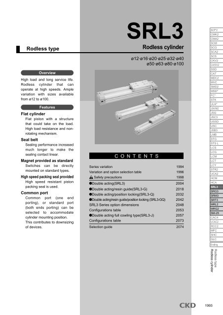
<strong>Rodless</strong> typeOverviewHigh load and long service life.<strong>Rodless</strong> <strong>cylinder</strong> that canoperate at high speeds. Amplevariation with sizes availablefrom ø12 to ø100.FeaturesFlat <strong>cylinder</strong>Flat piston with a structurethat could take on the load.High load resistance and nonrotatingmechanism.Seal beltSealing performance increasedmuch longer to make thesealing contact linear.Magnet provided as standardSwitches can be directlymounted on standard types.High speed packing seal providedHigh speed resistant pistonpacking seal is used.Common portCommon port (one endporting), or standard port(both ends porting) can beselected to accommodate<strong>cylinder</strong> mounting position.This contributes to downsizingof devices.<strong>SRL3</strong><strong>Rodless</strong> <strong>cylinder</strong>ø12·ø16·ø20·ø25·ø32·ø40ø50·ø63·ø80·ø100C O N T E N T SSeries variation 1994Variation and option selection table 1996Safety precautions 1998Double acting(<strong>SRL3</strong>) 2004Double acting/resin guide(<strong>SRL3</strong>-G) 2018Double acting/position locking(<strong>SRL3</strong>-Q) 2032Double acting/resin guide/position locking (<strong>SRL3</strong>-GQ) 2042<strong>SRL3</strong> Series option dimensions 2048Configurations table 2053Double acting·full cowling type(<strong>SRL3</strong>-J) 2057Configurations table 2073Selection guide 2074SCP*2CMK2CMA2SCMSCGSCA2SCSCKV2CA/OV2SSDCATMDC2MVCSMD2MSD*FC*STKULK*JSK/M2JSGJSC3USSDUSCJSB3LMBSTGSTS LLCSLCGLCMLCTLCYSTR2UCA2HCMHCA<strong>SRL3</strong>SRG3SRM3SRT3MRL2MRG2SM-25CAC4UCAC2RCC2MFCSHCGLCEnding<strong>Rodless</strong> type<strong>Rodless</strong> <strong>cylinder</strong>1993
Series variation<strong>Rodless</strong> <strong>cylinder</strong><strong>SRL3</strong> Series<strong>SRL3</strong> SeriesSeries variationSCP*2CMK2CMA2SCMSCGSCA2SCSCKV2CA/OV2SSDCATMDC2MVCSMD2MSD*FC*STKULK*JSK/M2JSGJSC3USSDUSCJSB3LMBSTGSTS LLCSLCGLCMLCTLCYSTR2UCA2HCMHCA<strong>SRL3</strong>SRG3SRM3SRT3MRL2MRG2SM-25CAC4UCAC2RCC2MFCSHCGLCVariationDouble actingstandard typeDouble actingresin guide typeDouble actingwithposition locking functionDouble acting withposition locking functionModel no.JIS symbol<strong>SRL3</strong><strong>SRL3</strong>-G<strong>SRL3</strong>-Q<strong>SRL3</strong>-GQBore size(mm)ø12, ø16, ø20ø25ø32ø40, ø50, ø63ø80, ø100ø12, ø16, ø20ø25ø32ø40, ø50, ø63ø80, ø100ø12, ø16, ø20ø25ø32ø40, ø50, ø63ø80, ø100ø12, ø16, ø20ø25ø32Standard stroke length (mm)200 300 400 500 600 700 800 900 1000Max. stroke lengthMin. stroke length(mm) (mm)500050001 500050005000500050001 500050005000500050001 500050005000500050001 5000Custom stroke length(mm)1111: Standard : Option : Custom order Not availableMounting style CushionOptionPageSwitchHeight adjustment plateTable mounting thread size upC mount brackeIntermediate support bracket LB1Intermediate support bracket 00Thin floating jointFloating jointAdjustable full stroke bracket to be installed laterAdjustable full-stroke L side with shock absorberAdjustable full-stroke R side with shock absorberAdjustable full-stroke both sides with shock absorberNo cushionL side cushionedR side cushionedBoth sides cushionedAxial foot typeAxial foot typeAxial foot typeBasic type00 LB LB1 LJ B R L N A A1 A2 A3 Y Y1 L* N* C H U2004201820322042SCP*2CMK2CMA2SCMSCGSCA2SCSCKV2CA/OV2SSDCATMDC2MVCSMD2MSD*FC*STKULK*JSK/M2JSGJSC3USSDUSCJSB3LMBSTGSTS LLCSLCGLCMLCTLCYSTR2UCA2HCMHCA<strong>SRL3</strong>SRG3SRM3SRT3MRL2MRG2SM-25CAC4UCAC2RCC2MFCSHCGLCEndingResin guide typeø40, ø50, ø635000EndingDouble actingfull cowling type<strong>SRL3</strong>-Jø80, ø100ø25ø32ø40, ø50, ø631500030003000300012057<strong>Rodless</strong> type<strong>Rodless</strong> <strong>cylinder</strong>19941995
<strong>SRL3</strong> G Q LB 20Model no.A Mounting styleVariationB Tube*Indicate symbols on the bore sizeleft table from left to rightModel no.: rodless <strong>cylinder</strong>C PipingscrewtypeBD Cushion200M0HE Stroke lengthF Switchmodel no.G Switch quantityVariation: Resin guide type, position lockingA Mounting style : Axial foot typeB Bore size : ø20mmC Port thread type : Rc threadD Cushion : Both sides cushionedE Stroke length : 200mmF Switch model no. : Reed MOH switch and lead wire 1mG Switch quantity : 2H Option : Adjustable full-stroke both sides, shock absorber and table mounting thread size upDA1H<strong>SRL3</strong> SeriesVariation and option selection tableH Option*Indicate symbols on the left table from left to rightSCP*2CMK2CMA2SCMSCGSCA2SCSCKV2CA/OV2SSDCATMDC2MVCSMD2MSD*FC*STKULK*JSK/M2JSGJSC3USSDUSCJSB3LMBSTGSTS LLCSLCGLCMLCTLCYSTR2UCA2HCMHCA<strong>SRL3</strong>SRG3SRM3SRT3MRL2MRG2SM-25CAC4UCAC2RCC2MFCSHCGLCEnding<strong>Rodless</strong> type<strong>Rodless</strong> <strong>cylinder</strong>1997
SCP*2CMK2CMA2SCMSCGSCA2SCSCKV2CA/OV2SSDCATMDC2MVCSMD2MSD*FC*STKULK*JSK/M2JSGJSC3USSDUSCJSB3LMBSTGSTS LLCSLCGLCMLCTLCYSTR2UCA2HCMHCA<strong>SRL3</strong>SRG3SRM3SRT3MRL2MRG2SM-25CAC4UCAC2RCC2MFCSHCGLCEndingIndividual precautions: rodless <strong>cylinder</strong> <strong>SRL3</strong> Series1.CommonCAUTIONPneumatic componentsSafety precautionsAlways read this section before starting use.Refer to Intro 71 for <strong>cylinder</strong>, and Intro 78 for <strong>cylinder</strong> switch.Please watch out when designing intermediate stop circuit.With a slit rodless <strong>cylinder</strong> such as the <strong>SRL3</strong>, some air leaksdue to the structure, so braking cannot be controlled with theall ports closed 3-position valve, and it may not be possible tohold the table stop position. Use a double sided pressurizedcontrol circuit having a P/A/B connection 3-position valve. If airpressure drops once and is then pressurized again unenergized,the table may move and the origin deviate.Basic circuit diagramHorizontal loadIf piping is as shown in Fig. 1, equal pressure is applied onboth sides of the piston when stopped, and the table will notpop out when restarting.Fig.1Vertical loadIf a vertical load is applied as shown in Fig. 2, the table will movein the direction of the load. Thus, install a regulator with check valveto reduce the thrust in the load direction and balance the load.Design & SelectionWith the slit rodless <strong>cylinder</strong>, such as the <strong>SRL3</strong>, externalair leaks at a level that does not affect speedcontrol.Do not use for applications that require constant pressurizationto only one side such as a balancer.2. Position locking type <strong>SRL3</strong>-QCAUTIONCylinder load factor must be 50% or less. If the loadfactor is high, the lock may not be released or thelock section could be damaged.When operating with 500mm/s or more, entry speedof position locking mechanism should be 500mm/sor less.Install an external shock absorber or deceleration circuit,etc. to decelerate.3. Full cowling type <strong>SRL3</strong>-JCAUTIONDo not use in an environment where it may contactwelding spatters, etc. Use the full cowling type superrodless <strong>cylinder</strong> (SR3-J) in this case.Precautions for full cowling type (<strong>SRL3</strong>-J)When installing a wall to keep dirt or coolant awayfrom the device, be sure the wall is nonmagnetic (aluminum,brass, etc.).For a magnetic material (steel plate, etc.), separatethe wall at least 20 mm from the switch edge.(all bore sizes)CylinderSwitch20mm and over1998Fig.2
1. CommonHow to adjust stroke adjustment unitStopper boltStopper boltsquare nutAdaptorfixing boltAdaptorWARNING(1) Moving the stroke adjustment unitThe stroke adjustment unit is moved by loosening the adapterfixing bolt (adapter fixing bolt and stroke adjustment plate fixingbolt for 12 to 25 mm bore).(2) Fixing the stroke adjustment unitAfter moving the stroke adjustment unit to the required position,tighten and fix the adapter fixing bolt (adapter fixing boltand stroke adjustment plate fixing bolt for 12 to 25 mm bore)using values in Table 8. If tightened at a lower value, the strokeadjustment unit may deviate.Table 1 Tightening torque for adapter fixing bolt and stroke adjustment plate fixing boltTightening torqueModel<strong>SRL3</strong>-12/16<strong>SRL3</strong>-20<strong>SRL3</strong>-25<strong>SRL3</strong>-32<strong>SRL3</strong>-40<strong>SRL3</strong>-50/63<strong>SRL3</strong>-80/100ø12 to ø25Adaptor fixing bolt(N/cm)100 to 120250 to 270520 to 5602200 to 24004400 to 48007700 to 830010000 to 11000Adjustable stroke platefixing boltAdjustable stroke plateShock absorbersquare nutShock absorber AdaptorInstallation & AdjustmentStopper boltsquare nutStopper boltAdjustable stroke plateFixing bolt(N/cm)50 to 70250 to 270––––(3)Stroke adjustment using stopper boltWith 12 to 20mm bore, clearance between the table andstroke adjustment plate is small, and fingers may be pinchedduring adjustment. The stroke must basically be adjustedby moving the stroke adjustment unit.Loosen the stopper bolt lock nut, turn the stopper bolt, andadjust the stroke.After adjusting the stroke, tighten and fix the stopper bolt locknut using values in Table 2.(4) Adjusting shock absorberShock absorber absorbed energy is adjusted by changing theworking stroke of the shock absorber.Adjust the shock absorber working stroke by loosening theshock absorber lock nut and turning the shock absorber. Afteradjusting, tighten the shock absorber fixing nut with the tighteningtorque shown below.{ }ø32 to ø63Adaptorfixing boltShock absorbersquare nutShock absorberTable 2 Tightening torque of stopper bolt fixing nut, shock absorber fixing nutTightening torqueModel<strong>SRL3</strong>-12/16<strong>SRL3</strong>-20<strong>SRL3</strong>-25<strong>SRL3</strong>-32<strong>SRL3</strong>-40<strong>SRL3</strong>-50<strong>SRL3</strong>-63<strong>SRL3</strong>-80/100Cylinder strokeendType type<strong>SRL3</strong>-12/16<strong>SRL3</strong>-20<strong>SRL3</strong>-25<strong>SRL3</strong>-32<strong>SRL3</strong>-40<strong>SRL3</strong>-50/63<strong>SRL3</strong>-80/100AdaptorStopper boltsquare nutStopper boltSlight marginat shock absorberstroke.Square nut(N/cm)110 to 120250 to 270880 to 9502200 to 24004400 to 48007700 to 830020000 to 2160021500 to 23500ø80 to ø100Adjust the position of theshock absorber untilthe rod end touches it.Cylinder strokeendAbsorbed energy (J)2.45.710185086143<strong>SRL3</strong> SeriesSpecific precautionsAdaptorfixing boltShock absorbersquare nutShock absorberSquare nut(N/cm)130 to 180290 to 390450 to 600750 to 10002200 to 30005500 to 70005500 to 700010000 to 13000(5)Precautions upon useThe shock absorber absorbs rated energy with the ratedstroke. When the product is shipped, the shock absorber isinstalled with a slight margin to the stroke at the <strong>cylinder</strong> strokelimit.Absorbed energy is smaller than allowable energy absorptionfor the individual shock absorber, so if rated absorbed energyis required, adjust so the full stroke for the shock absorberis used.(note) This is a descriptionof the shock absorberincluded in the full stroke adjustment type.Allowable energy absorption differs with collision speed, so if collisionspeed is 2000 mm/s, check that one-third of the maximum energyabsorption in Table 3 is not exceeded. If collision speed is 1000 mm/s,check that one-half of the maximum energy absorption is not exceeded.Table 3 Adjustable full-stroke shock absorber specifications (initial setpoint)Valid mm stroke (mm)5.5791316.52125SCP*2CMK2CMA2SCMSCGSCA2SCSCKV2CA/OV2SSDCATMDC2MVCSMD2MSD*FC*STKULK*JSK/M2JSGJSC3USSDUSCJSB3LMBSTGSTS LLCSLCGLCMLCTLCYSTR2UCA2HCMHCA<strong>SRL3</strong>SRG3SRM3SRT3MRL2MRG2SM-25CAC4UCAC2RCC2MFCSHCGLCEnding<strong>Rodless</strong> type<strong>Rodless</strong> <strong>cylinder</strong>1999
<strong>SRL3</strong> SeriesSCP*2CMK2CMA2SCMSCGSCA2SCSCKV2CA/OV2SSDCATMDC2MVCSMD2MSD*FC*STKULK*JSK/M2JSGJSC3USSDUSCJSB3LMBSTGSTS LLCSLCGLCMLCTLCYSTR2UCA2HCMHCA<strong>SRL3</strong>SRG3SRM3SRT3MRL2MRG2SM-25CAC4UCAC2RCC2MFCSHCGLCEndingCAUTIONAvoid electrical welding after installing the rodless<strong>cylinder</strong>.If the current flows into the <strong>cylinder</strong> and generates sparks betweenthe dust-proof belt and <strong>cylinder</strong> tube, the dust-proof beltmay be damaged.If a unit with excessive inertia, etc., is moved, the<strong>cylinder</strong> may be damaged or faulty operation occur.Use only within the allowable range.Do not apply shock or excessive moment on the table.Align before connecting to an load with an externalguide mechanism.Carefully consider connection (floating) so deviation isabsorbed.The longer the stroke, the greater the shaft centermay deviate.Check that moment, including inertia generated when movingor stopping the load, does not exceed the allowable load, ordamage may result. Exceeding this value will result in damage.(When the overhang is large)If overhang is large and the <strong>cylinder</strong> is stopped at both endswith the piston, the bending moment functions due to loadinertia even within internal cushion energy absorption.If kinetic energy is large and an external cushion, etc., is used,try contact with the work-piece center of gravity when possible.(When using an external stopper)When selecting an external stopper, consider the bendingmoment generated by <strong>cylinder</strong> thrust.Moment that functions when stopping with external stopperFM1=F/(When using an external guide)When an external guide is installed, if the center is not aligned,movement is not smooth and resistance caused by twistingfunctions as moment.Example of guide useF: Cylinder thrust: Distance from <strong>cylinder</strong>center to stopperPiping port position and operating directionBore size ø12 to 20.Option symbol (Blank, R, B, T)L2L0L sideL2L0L0R indicates R side pressurized port and L indicates L side pressurizedport. Before shipping, all ports other than 1 each at R and L are sealedwith plugs. Piping to other ports becomes possible by removing plug.Option symbol (D, S) are not available.Bore size ø25 to ø63.Option symbol (Blank, R, B, T)L3R0R0L1R1R sideR indicates R side pressurized port and L indicates L side pressurizedport. Before shipping, all ports other than 1 each at R and Lare sealed with plugs. Piping to other ports becomes possible byremoving plug. However, bottom side piping is not possible. Selectoptions (D, S) if such connection is necessary.For option symbols (D, S) (bottom piping)L2L0L sideL sideL0L0L2R indicates R side pressurized port and L indicates L side pressurized port.L here are no ports other than R2 or L2 , so pipes cannot be connected.R0R0R2L1R1R sideR sideR0L3R0L1R1L1R1R22000
<strong>SRL3</strong> SeriesSpecific precautionsBore size ø80 and 100.Option symbol (Blank, R, B, T)L0L sideL0L0R indicates R side pressurized port and L indicates L side pressurizedport. Before shipping, all ports other than 1 each at R and L are sealedwith plugs. Piping to other ports becomes possible by removing plug.For option symbols (D, S) (bottom piping)L3L sideL3L3L1R0L1R0R1L2R sideThere are no ports other than R2 or L3 , so pipes cannot be connected.R2R2R side<strong>CKD</strong> shock absorbers are consumables.Replace the shock absorber if energy absorptionperformance drops or if movement is no longersmooth.Mount the switch in parallel to the mounting grooveso that force is not applied on the lead wires.Cylinder switchCylinderR0R1Install on parallelL2L1R22. Position locking type <strong>SRL3</strong>-QWARNINGHow to adjust stroke adjustment unitPosition locking unitLock pinModel<strong>SRL3</strong>-Q-12/16<strong>SRL3</strong>-Q-20<strong>SRL3</strong>-Q-25<strong>SRL3</strong>-Q-32<strong>SRL3</strong>-Q-40<strong>SRL3</strong>-Q-50/63<strong>SRL3</strong>-Q-80/100AdaptorAdaptorFixing boltPosition locking unit can be moved by loosening the adaptorfixing bolt.Select shock absorber (A, A1, A2) in this case. If the stroke isfinely adjusted with the shock absorber, the position lockingunit deviates and the position cannot be completely locked.Finely adjust stroke with the adapter fixing bolt.After moving to the required position, tighten and fix theadapter fixing bolt using the values below. The position lockingunit may deviate if the bolt is not tightened to these values.Check that the locking mechanism works when a load is set.Adaptor fixing bolt tightening torque(N•cm)100 to 120250 to 280520 to 5602200 to 24004400 to 48007700 to 830010000 to 11000PipingPiping is required for the position locking unit.LoadPort RPosition locking unit portPort L (side without locking mechanism)Branch pipe to the rodless <strong>cylinder</strong> R side using a tee union,etc., and pipe to the position locking unit with similar piping.If the piping on the side where the locking mechanism is providedis long and thin, or if the speed controller is separatedfrom the <strong>cylinder</strong> port, the exhaust speed will drop and it maytake longer for the lock to be applied. This may also occur ifthe silencer on the valve's EXH port is clogged.SCP*2CMK2CMA2SCMSCGSCA2SCSCKV2CA/OV2SSDCATMDC2MVCSMD2MSD*FC*STKULK*JSK/M2JSGJSC3USSDUSCJSB3LMBSTGSTS LLCSLCGLCMLCTLCYSTR2UCA2HCMHCA<strong>SRL3</strong>SRG3SRM3SRT3MRL2MRG2SM-25CAC4UCAC2RCC2MFCSHCGLCEnding<strong>Rodless</strong> type<strong>Rodless</strong> <strong>cylinder</strong>Supply pressure above the minimum working pressureto the position locking unit port.2001
<strong>SRL3</strong> SeriesSCP*2CMK2CMA2SCMSCGSCA2SCSCKV2CA/OV2SSDCATMDC2MVCSMD2MSD*FC*STKULK*JSK/M2JSGJSC3USSDUSCJSB3LMBSTGSTS LLCSLCGLCMLCTLCYSTR2UCA2HCMHCA<strong>SRL3</strong>SRG3SRM3SRT3MRL2MRG2SM-25CAC4UCAC2RCC2MFCSHCGLCEndingUnlocking manuallyRelease the position locking pin with a rod-shaped object.Supply pressure to port L to check that load is not applied tothe locking mechanism before releasing the lock.If both ports R and L are exhausted and pressure is suppliedto port R while the piston is locked, the lock is released andthe table may suddenly move, creating a hazard.Lock pinValvesIf the <strong>cylinder</strong> is held while pressure is applied on the lockingmechanism, the locking pin may dislocate and cause danger.Do not use a 3-position closed center or P/A/B connectionvalve.If back pressure is applied while locked, the lock may bereleased. Use a discrete valve, or use an individual exhaustmanifold.Dropping speed is increased with a quick exhaust valve, the<strong>cylinder</strong> may move faster than the locking pin and preventproper release.Do not use quick exhaust valves for position locking <strong>cylinder</strong>s.3. Full cowling type <strong>SRL3</strong>-JCAUTIONTake care not to catch hands or fingers when adjustingthe switch.Avoid installing in reverse. Dirt may accumulate oroperation be inhibited by accumulated fluid.2002
1. Position locking type <strong>SRL3</strong>-QWARNINGFor safety purposes, prevent the load from droppingunder its own weight during maintenance.When using the <strong>cylinder</strong> with air cushion, if the aircushion needle on the lock mechanism side is tootight, the piston could bounce at the stroke end causingthe lock lever and lock pin to collide and damagethe locking mechanism. If the air cushion needle isopened too far, the piston could spring back at thestroke end and cause similar damage. Adjust the aircushion needle so that the piston does not bounce.When stopping with an external shock absorber, etc.,adjust in the same way to prevent bouncing.Regularly (once or twice a year) check that the holdingsection is not damaged by this symptom.CAUTIONIf the locking mechanism has been manually operated,check and then return it manually to the originalposition.Do not use a manual override exceptduring adjustment.Release the lock when installing or adjusting the <strong>cylinder</strong>.The lock could be damaged if the <strong>cylinder</strong> isinstalled while the lock is applied.Do not use multiple <strong>cylinder</strong>s synchronized. Do notmove more than one workpiece using more than two<strong>cylinder</strong>s with position locking mechanism simultaneously.One of the <strong>cylinder</strong>s may become unable tounlock.Use the speed control valve with meter-out control.Locks may not be released during meter-in control.Always use up to the stroke end of the side with thelock. If the <strong>cylinder</strong>'s piston does not reach the strokeend, the lock may not be applied or may not be released.Apply grease to sliding section of lock lever periodically.During Use & Maintenance2. Full cowling type <strong>SRL3</strong>-JCAUTIONSuspended particles such as fiber, feathers, or powdermay pass through the table adapter passage underthe cover and adhere to the <strong>cylinder</strong>, leading tooperation faults.If coolant (oil) or cutting chips scatter with force, or ifthey scatter from an inclined direction, provide anothercover on the <strong>cylinder</strong> and sides, etc.Do not let particles get stuck in the clearance of 2 to3mm between the sliding section(table adaptor) andthe cover.Regularly remove particles on top of the cover and inside thecover. The product may be damaged if this is left as is.This product provides clearance under the cover for passingthe table adapter through. Therefore, there is a risk of particlesentering the cover.Do not get on the cover. It could break.<strong>SRL3</strong> SeriesSpecific precautionsSCP*2CMK2CMA2SCMSCGSCA2SCSCKV2CA/OV2SSDCATMDC2MVCSMD2MSD*FC*STKULK*JSK/M2JSGJSC3USSDUSCJSB3LMBSTGSTS LLCSLCGLCMLCTLCYSTR2UCA2HCMHCA<strong>SRL3</strong>SRG3SRM3SRT3MRL2MRG2SM-25CAC4UCAC2RCC2MFCSHCGLCEnding<strong>Rodless</strong> type<strong>Rodless</strong> <strong>cylinder</strong>2003
SCP*2CMK2CMA2SCMSCGSCA2SCSCKV2CA/OV2SSDCATMDC2MVCSMD2MSD*FC*STKULK*JSK/M2JSGJSC3USSDUSCJSB3LMBSTGSTS LLCSLCGLCMLCTLCYSTR2UCA2HCMHCA<strong>SRL3</strong>SRG3SRM3SRT3MRL2MRG2SM-25CAC4UCAC2RCC2MFCSHCGLCEndingSpecificationsDescriptionsBore sizeActuationWorking fluidMax. working pressureMin. working pressureWithstanding pressureAmbient temperaturePort sizeStroke toleranceWorking piston speedCushionLubricationmmMPaMPaMPammmm/s<strong>SRL3</strong>ø12 ø16 ø20 ø25 ø32 ø40 ø50 ø63 ø80Double actingCompressed air0.70.2 0.10.051.055 to 60M5Rc 1 /8Rc 1 /4Rc 3 /8+ 2.0 + 2.50 (up to 1000), 0 (up to 3000), (up to 5000)Rc 1 /2ø10050 to 2000 (standard port piping) (note 1)Air cushionNot required (continuously lubricate using turbine oil class 1 ISOVG32 if lubricated.)Note 1: Piston speed used with common port piping differs depending on the stroke. Contact <strong>CKD</strong> for details.Allowable energy absorptionBore size(mm)ø12ø16ø20ø25ø32ø40ø50ø63ø80ø100CushionedNo cushionAllowable energy absorption (J) Cushion mm stroke (mm) Allowable energy absorption (J) Absorbed energy (J) Valid mm stroke (mm)0.030.220.591.402.574.279.1317.4406714.519.222.220.923.523.924.929.645.845.80.0030.0070.0100.0150.0300.0500.0720.1380.3930.6222.42.45.710185086861431435.55.5791316.521212525Note: The minimal stroke for full stroke adjustment models with switches are shown in ( ).+ 3.00With shock absorber (initial setpoint)M type switch quantity and min. stroke length (mm)Switch quantitySwitch model no.Bore size (mm)M*V1M*Hø1210 10 30 45(70) 60 90(120)ø1610 10 30 45(70) 60 90(120)ø2010 10 30 45(70) 60 90(120)ø2510 10 30 45(70) 60 90(120)ø3210 10 30 45 60 90ø4010 10 30 45 60 90ø5015 15 30 45 60 90ø6315 15 30 45 60 90ø802550100ø1002550100Note: The minimal stroke for full stroke adjustment models with switches are shown in ( ).Switch quantitySwitch model no.Bore size (mm)ø12ø16ø20ø25ø32ø40ø50ø63ø80ø100T*V555101010101015151T*H55510101010101515<strong>Rodless</strong> <strong>cylinder</strong><strong>SRL3</strong> SeriesBore size :JIS symbolM*V2M*HM*VT type switch quantity and min. stroke length (mm)T*V454545454545454545452T*H50(70)50(70)50(70)50(70)505050505050T*V85858585858585858585ø12, ø16, ø20, ø25, ø32ø40, ø50, ø63, ø80, ø10033M*HT*H100(120)100(120)100(120)100(120)100100100100100100Stroke lengthBore size(mm)ø12ø16ø20ø25ø32ø40ø50ø63ø80ø100M*V9090909090909090T*V12512512512512512512512512512541501504M*H135(170)135(170)135(170)135(170)135135135135T*H150(170)150(170)150(170)150(170)150150150150150150Standard stroke length(mm)200,300400,500600,700800,9001000M*V5Max. stroke length(mm)M*H5000120 180(220)120 180(220)120 180(220)120 180(220)120 180120 180120 180120 180200200T*V1651651651651651651651651651655T*H200(220)200(220)200(220)200(220)200200200200200200M*VMin. stroke length(mm)** The intermediate stroke can be manufactured in 1 mm increments.6M*H150 225(270)150 225(270)150 225(270)150 225(270)150 225150 225150 225150 225250250T*V20520520520520520520520520520561T*H250(270)250(270)250(270)250(270)2502502502502502502004
Switch specifications (M type switch)(1) 1color /2 color displayDescriptionsApplicationsOutput methodPower voltageLoad voltageLoad currentLightLeakage currentDescriptionsApplicationsPower voltageLoad voltageLoad currentLightLeakage currentSwitch specifications (T type switch)2 Color indicator typeDescriptionsApplicationsOutput methodPower voltageLoad voltageLoad currentLightLeakage currentStrong magnetic field proofDescriptionsApplicationsLightLoad voltageLoad currentInternal voltage dropLeakage currentCylinder weightBore size (mm)ø12ø16ø20ø25ø32ø40ø50ø63ø80ø100Proximity 2 wireM2WVM2V and M2H(2 color indicator type)PLC––10 to 30 VDC5 to 30mALED (ON lighting) Red/green LED (ON lighting)1mA or less12/24 VDC5 to 50mAM0V and M0HPLC, relay–110 VAC7 to 20mALED (ON lighting)Without indicator light0mANote 1: For M0* switch, if load current is within 7 to 20mA, this switch can be used with 24 VAC and 48 VAC.Note 2: Refer to Ending 1 for specifications of other switches.Proximity 2 wireT2YH/T2YVT2WH/T2WVPLC––10 to 30 VDC24 VDC ±10%5 to 20mARed/greenLED(ON lighting)1mA or lessProximity switchT2YD and T2YDTPLCRed/green LED (ON lighting)24 VDC ±10%5 to 20mA6V or less1.0mA or lessWeight when stroke length is 0mmBasic type Foot type Weight per switch(00) (LB) (LB1) (Including bracket)0.24 0.25 0.260.32 0.33 0.350.52 0.54 0.581.0 1.1 1.11.5 1.6 1.72.4 2.5 –0.023.5 3.6 –6.1 6.4 –18.4 19.0 –26.2 27.2 –Proximity 3 wireM3H/M3VM3PH/M3PV(Custom order)M3WVPLC, relay, IC circuit or small solenoid valveNPN output PNP outputNPN output4.5 to 28 VDC10 to 28 VDC30 VDC or less200mA or less 100mA or less150mA or lessLED (ON lighting) Yellow LED (ON lighting) Red/green LED (ON lighting)10µA or less 0.05mA or less 10µA or lessReed 2 wireM5V and M5HPLC, relay, IC circuit (w/o lamp), serial connection–Red/greenLED(ON lighting)5/12/24 VDC50mA or lessRed/greenLED(ON lighting)Unit: kgAdditionalweight perSt=100mm0.100.130.180.280.360.530.751.112.323.3810µA or less<strong>SRL3</strong> SeriesSpecifications110 VAC or less20mA or lessProximity 3 wireT3YH/T3YVT3WH/T3WVPLC, relayNPN outputNPN output10 to 28 VDC30 VDC or less50mA or lessRed/greenLED(ON lighting)SCP*2CMK2CMA2SCMSCGSCA2SCSCKV2CA/OV2SSDCATMDC2MVCSMD2MSD*FC*STKULK*JSK/M2JSGJSC3USSDUSCJSB3LMBSTGSTS LLCSLCGLCMLCTLCYSTR2UCA2HCMHCA<strong>SRL3</strong>SRG3SRM3SRT3MRL2MRG2SM-25CAC4UCAC2RCC2MFCSHCGLCEnding<strong>Rodless</strong> type<strong>Rodless</strong> <strong>cylinder</strong>2005
<strong>SRL3</strong> SeriesSCP*2CMK2CMA2SCMSCGSCA2SCSCKV2CA/OV2SSDCATMDC2MVCSMD2MSD*FC*STKULK*JSK/M2JSGJSC3USSDUSCJSB3LMBSTGSTS LLCSLCGLCMLCTLCYSTR2UCA2HCMHCA<strong>SRL3</strong>SRG3SRM3SRT3MRL2MRG2SM-25CAC4UCAC2RCC2MFCSHCGLCEnding2006How to orderWithout switch<strong>SRL3</strong> 00 12 B 200 BWith switch<strong>SRL3</strong>0012A Mounting styleNote 1B Bore sizeC Port thread typeD Cushion<strong>SRL3</strong>-00-12B-200-M0H-R-B200 M0HE Stroke lengthRBF Switch model no.Note 3Model: <strong>Rodless</strong> <strong>cylinder</strong>A Mounting style : Basic typeB Bore size : ø12mmC Port thread type : Rc threadD Cushion : Both sides cushionedE Stroke length : 200mmF Switch model no. : Reed switch M0H and lead wire 1mG Switch quantity : 1 on rod endH Option: Port position F, cushion needle position BBNote on model no. selectionNote 1: When bore size 12, 16, 20, 25, 32 and option symbol"R" and "T" is selected,mounting style will be "00"or "LB1".(Mounting style "LB" is not available for optionsymbol "R" and "T" because it can not be piped )Note 2: Refer to page 2004 for minimum stroke with switch.Note 3: Switches not listed on option "F" are also available.Refer to Ending 1 for more details (custom order)Note 4: The "*" mark on L* and N* indicates the quantity ofsets. If 2 sets are required, fill in "L2" for LB and"N2" for LB1. 2 pcs./setNote 5: Refer to dimensions on page 2026 to 2031for port,cushion needle position indication symbol.Note 6: Standard models of ø12 to ø15 needs to have theircover removed and full stroke adjustment mountedusing a plate nut afterwards."A3" is a option that will have a plate nut for mountinginstalled beforehand so that it can be mountedafterwards without removing the cover.Note 7: Thread size will be M4 for ø12 and ø16, and threadsize will be M5 for ø20 when "H" is selected.Note 8: Refer to "Optional combination table" on thefollowing page for available combinations.Note 9: Copper and PTFE free as standard.G Switch quantityH OptionNote 4, Note 5Note 6, Note 7Note 8SymbolA Mounting style00 Basic typeLB Axial foot typeLB1 Axial foot typeB Bore size (mm)121620253240506380100CBlankNGø12ø16ø20ø25ø32ø40ø50ø63ø80ø100*Lead wire lengthBlank 1m (standard)3 3m (option)5 5m (option)G Switch quantityR One on R sideL One on L sideD 2T 34 4 pieces (fill in switch quantity if 4 or more switches are required.)H Option Bore size (ø)Bore size(ø)Adjustable full-stroke R end only, with shock absorberAdjustable full-stroke L end only, with shock absorberAdjustable full-stroke bracket retrofittingFloating jointThin floating jointIntermediate support bracket (00, LB)With intermediate support bracket (LB1)C mount bracketTable mounting thread size upHeight adjustment plateF (standard)R (common port)FR (common port)DDF (common port)F (standard)FBBFDFDescriptionsD CushionBRLNBoth sides cushionedR side cushionedL side cushionedNo cushionE Stroke length (mm)Bore size Stroke length Note 2 Custom stroke lengthø12 to ø1001 to 5000 By 1 mm incrementF Switch model no.Lead wire Lead wireLeadIndicatorAxialRadialwireAA1A2A3YY1L*N*CHUBlankRBTDSXPort thread typeRc threadNPT thread (ø20 and over) (custom order)G thread (ø20 and over) (custom order)M0H*M5H*M2H*–M3H*–M3PH*T2WH*T2YH*T3WH*T3YH*T2YD*T2YDT*Port positionM0V*M5V*M2V*M2WV*M3V*M3WV*M3PV*T2WV*T2YV*T3WV*T3YV*––Cushion needle positionContact Reed Proximity1 color indicator typeWithout indicator light1 color indicator type2 color indicator type1 color indicator type2 color indicator type1 color indicator type (custom order)2 color indicator typeStrong magnetic field proof(AC magnetic field dedicated)2-wire2-wire3-wire3-wire2-wire3-wire2-wire12 16 20 25 32 40 50 63 80 100
Option combination table: Combination available : Combination not availableOptionSymbolAA1A2A3YY1L*N*CHUBlankRBTDSXOptionHeight adjustment plateTable mounting thread size upC mount bracketIntermediate support bracket (LB1)Intermediate support bracket (00, LB)Thin type floating jointFloating jointAdjustable full-stroke bracket retrofittingAdjustable full-stroke L end only, with shock absorberAdjustable full-stroke R end only, with shock absorberAdjustable full-stroke both ends, with shock absorberA A1 A2 A3Port position and cushion needle position F (common port)Port position D, cushion needle position DPort position D, cushion needle position FPort position R, cushion needle position B (common port)Port position F, cushion needle position BPort position R, cushion needle position F (common port)Port position F, cushion needle position F (standard)Y Y1 L* N* C H U Blank R B T D S XNote 1: Some combinations are not available depending on bore size. Confirm the conditions of options of H "How to order" on the previous page.Note 2: LB1 can not be used if port position is D. (ø25, ø32)<strong>SRL3</strong> SeriesHow to orderSCP*2CMK2CMA2SCMSCGSCA2SCSCKV2CA/OV2SSDCATMDC2MVCSMD2MSD*FC*STKULK*JSK/M2JSGJSC3USSDUSCJSB3LMBSTGSTS LLCSLCGLCMLCTLCYSTR2UCA2HCMHCA<strong>SRL3</strong>SRG3SRM3SRT3MRL2MRG2SM-25CAC4UCAC2RCC2MFCSHCGLCEnding<strong>Rodless</strong> type<strong>Rodless</strong> <strong>cylinder</strong>2007
<strong>SRL3</strong> SeriesSCP*2CMK2CMA2SCMSCGSCA2SCSCKV2CA/OV2SSDCATMDC2MVCSMD2MSD*FC*STKULK*JSK/M2JSGJSC3USSDUSCJSB3LMBSTGSTS LLCSLCGLCMLCTLCYSTR2UCA2HCMHCA<strong>SRL3</strong>SRG3SRM3SRT3MRL2MRG2SM-25CAC4UCAC2RCC2MFCSHCGLCEndingHow to order switchSwitch body + mounting bracket (Note 1)<strong>SRL3</strong>Switch model no.(Page 2006 F section)Only switch bodySWMounting bracket (Note 2)• M type switch<strong>SRL3</strong>Lead wire holder (Note 3)<strong>SRL3</strong>Discrete shock absorber model no.<strong>SRL3</strong>M0H*M0H*Switch model no.(Page 2006 section F )MMHNCKApplicable shock absorber model No.Model Shock absorber model no.<strong>SRL3</strong>-12 NCK-00-0.3-C<strong>SRL3</strong>-16 NCK-00-0.3-C<strong>SRL3</strong>-20 NCK-00-0.7-C<strong>SRL3</strong>-25 NCK-00-1.2<strong>SRL3</strong>-32 NCK-00-2.6<strong>SRL3</strong>-40 NCK-00-7<strong>SRL3</strong>-50 NCK-00-12<strong>SRL3</strong>-63 NCK-00-12<strong>SRL3</strong>-80 NCK-00-20<strong>SRL3</strong>-100 NCK-00-20C(Refer to page 2053 to 2055 for configurations )*Lead wire lengthBlank 1m (standard)33m (option)55m (option)"*" mark indicates length of lead wire.• T type switch<strong>SRL3</strong>Note 1: Lead wire holder is not included in the switch and its mounting bracket.When a lead wire holder is necessary, place an order separately.Note 2: M type switch and T type switch has different brackets.Note 3: Lead wire holder comes in a set of 10 pcs.(Square nut 1 pc., hex nut for fixing shock absorber 1pc.)Square nut for shock absorber for <strong>SRL3</strong>-40 is a special design.Discrete C mount bracket model no. (for ø12 to ø63)<strong>SRL3</strong>(C mount bracket and mounting bolt 4 pc.)Floating joint set model no.<strong>SRL3</strong>40Bore size(Page 2006 B section)40Bore size(Page 2006 section B )40YBore size(Page 2006 section B )(Mount, mount base, pin, plain washer, pan head machinescrew with spring washer and 4 mounting bolts)TDiscrete intermediate support bracket model no.LB<strong>SRL3</strong>LB1<strong>SRL3</strong>Adjustable full-stroke kit model no.<strong>SRL3</strong>Repair parts model no.<strong>SRL3</strong>KMounting bracket model no.<strong>SRL3</strong>Mounting style(LB and LB1)Bore size(Page 2006 section B )(Plate and mounting bolt 4 pc.)A1 (1 set)Height adjustment plate set model no.<strong>SRL3</strong>40Bore size(Page 2006 section B )A40Bore size(Page 2006 B section)324040LBore size(Page 2006 section B )Bore size(Page 2006 section B )U(2 piece/1 set)N (2 piece/1 set)200Stroke length(Page 2006 section E )40(Bracket 2 piece and mounting bolt 4 pc.)Bore size(Page 2006 section B )2008
<strong>SRL3</strong> SeriesInternal structure and parts listInternal structure and parts listParts listNo. Parts name Material Remarks12345Belt coverCover (L)Table coverSpringBelt tensionPolyamideAluminum alloyPolyacetal resinSteelPolyacetal resinBaking finishBlackening6Parallel pin (ø12 to ø20) Stainless steelShaft (ø25 to ø40) SteelGalvanizing7891011121314151617TableSeal beltDust-proof beltMagnetCushion adapterCover (R)Belt spacerHexagon socket set screwHexagon socket boltHexagon socket boltHexagon socket boltAluminum alloyUrethane rubberStainless steel + nitrile rubberSpecial alloyPolyacetal resinAluminum alloySteelAlloy steelAlloy steelStainless steelAlloy steelAlumiteNickelingBaking finishGalvanizingGalvanizingGalvanizingGalvanizingRepair parts listTubeBore size (mm)ø12ø16ø12 to ø40.28 15 18 16 19 17 1 2 21 3 4 5 22 6 23 7 8 9 10 29 30 31 24 25 11 26 12 13 14 27 20Kit No.<strong>SRL3</strong>-12K-*<strong>SRL3</strong>-16K-*Repair parts numberNo. Parts name Material Remarks1819Needle gasketCushion needleNitrile rubberSteelGalvanizing20Plug (ø12, ø16) BrassNickelingPlug (ø20 to ø40) SteelGalvanizing212223242526272829Cushion packing sealPiston packing sealYokePistonCylinder tubeCylinder gasketO ring for common portDust wiper2-side adhesive tapeUrethane rubberNitrile rubberAluminum alloyPolyacetal resinAluminum alloyNitrile rubberNitrile rubberPolyacetal resinStainless steel (ø12 to ø20)AlumiteAlumite3031PlateCross-recessed tapping screwAlloy steel (ø25 to ø40)Stainless steelGalvanizingSCP*2CMK2CMA2SCMSCGSCA2SCSCKV2CA/OV2SSDCATMDC2MVCSMD2MSD*FC*STKULK*JSK/M2JSGJSC3USSDUSCJSB3LMBSTGSTS LLCSLCGLCMLCTLCYSTR2UCA2HCMHCA<strong>SRL3</strong>SRG3SRM3SRT3MRL2MRG2SM-25CAC4UCAC2RCC2MFCSHCGLCø20<strong>SRL3</strong>-20K-*8 9 18 21Endingø25ø32ø40<strong>SRL3</strong>-25K-*<strong>SRL3</strong>-32K-*<strong>SRL3</strong>-40K-*22 26 27 28<strong>Rodless</strong> type<strong>Rodless</strong> <strong>cylinder</strong>Note: Specify the kit no. when placing an order.Specify the stroke length for *.2009
<strong>SRL3</strong> SeriesSCP*2CMK2CMA2SCMSCGSCA2SCSCKV2CA/OV2SSDCATMDC2MVCSMD2MSD*FC*STKULK*JSK/M2JSGJSC3USSDUSCJSB3LMBSTGSTS LLCSLCGLCMLCTLCYSTR2UCA2HCMHCA<strong>SRL3</strong>SRG3SRM3SRT3MRL2MRG2SM-25CAC4UCAC2RCC2MFCSHCGLCInternal structure and parts listParts listNo. Parts name Material Remarks12345678910111213141516Belt coverCover (L)Table coverSpringBelt tensionShaftTableSeal beltDust-proof beltMagnetCushion ringCover (R)Belt spacerHexagon socket set screwHexagon socket boltHexagon socket boltPolyamideAluminum alloyPolyacetal resinSteelPolyacetal resinSteelAluminum alloyUrethane rubberStainless steel + nitrile rubberSpecial alloyPolyacetal resinAluminum alloySteelAlloy steelAlloy steelStainless steelBaking finishBlackeningGalvanizingAlumiteNickelingBaking finishGalvanizingGalvanizingGalvanizingRepair parts listTubeBore size (mm)ø50ø63ø50 to ø63.28 16 15 18 19 17 1 2 3 4 5 6 7 8 9 10 23 24 29 30 31 22 21 25 11 26 27 12 13 14 32 20Kit No.<strong>SRL3</strong>-50K-*<strong>SRL3</strong>-63K-*Repair parts number8 9 18 21 2226 27 28 32Note: Specify the kit no. when placing an order Specify stroke length for "*".No. Parts name Material Remarks17181920212223242526272829303132Hexagon socket boltNeedle gasketCushion needlePlugCushion packing sealPiston packing sealYokePistonCylinder tubeCylinder gasketO ring for common portDust wiper2-side adhesive tapePlateCross-recessed tapping screwCushion ring gasketAlloy steelNitrile rubberSteelSteelUrethane rubberNitrile rubberAluminum alloyPolyacetal resinAluminum alloyNitrile rubberNitrile rubberPolyacetal resinAlloy steelStainless steelNitrile rubberGalvanizingGalvanizingGalvanizingAlumiteAlumiteGalvanizingEnding2010
Internal structure and parts listParts listNo. Parts name Material Remarks1234567891011121314151617Belt coverCover (L)Table coverSpringBelt tensionShaftTableSeal beltDust-proof beltMagnetCushion ringCover (R)Belt spacerHexagon socket set screwHexagon socket boltHexagon socket boltHexagon socket boltRepair parts listø80ø100ø80 to ø100.TubeBore size (mm)16 15 18 19 17 1Kit No.<strong>SRL3</strong>-80K-*<strong>SRL3</strong>-100K-*PolyamideAluminum alloyPolyacetal resinSteelPolyacetal resinSteelAluminum alloyUrethane rubberStainless steel + nitrile rubberSpecial alloyPolyacetal resinAluminum alloySteelAlloy steelAlloy steelStainless steelAlloy steelBaking finishBlackeningGalvanizingAlumiteNickelingBaking finishGalvanizingGalvanizingGalvanizingGalvanizingNote: Specify the kit no. when placing an order Specify stroke length for "*".2910Repair parts number8 9 18 21 22 2627 28 29 32 33No. Parts name Material Remarks1819202122232425262728293031323334Needle gasketCushion needlePlugCushion packing sealPiston packing sealYokePistonCylinder tubeCylinder gasketO ring for common portFelt (1)Felt (2)PlateCross-recessed tapping screwCushion ring gasket (1)Cushion ring gasket (2)Plug<strong>SRL3</strong> SeriesInternal structure and parts list2 28 3 4 5 6 7 8 9 23 30 31 24 22 21 25 11 26 13 14 12 32 2027 34 33Nitrile rubberSteelSteelUrethane rubberNitrile rubberAluminum alloyPolyacetal resinAluminum alloyNitrile rubberNitrile rubberWoolWoolAlloy steelStainless steelNitrile rubberNitrile rubberSteelGalvanizingGalvanizingAlumiteAlumiteGalvanizingGalvanizingSCP*2CMK2CMA2SCMSCGSCA2SCSCKV2CA/OV2SSDCATMDC2MVCSMD2MSD*FC*STKULK*JSK/M2JSGJSC3USSDUSCJSB3LMBSTGSTS LLCSLCGLCMLCTLCYSTR2UCA2HCMHCA<strong>SRL3</strong>SRG3SRM3SRT3MRL2MRG2SM-25CAC4UCAC2RCC2MFCSHCGLCEnding<strong>Rodless</strong> type<strong>Rodless</strong> <strong>cylinder</strong>2011
<strong>SRL3</strong> SeriesSCP*2CMK2CMA2SCMSCGSCA2SCSCKV2CA/OV2SSDCATMDC2MVCSMD2MSD*FC*STKULK*JSK/M2JSGJSC3USSDUSCJSB3LMBSTGSTS LLCSLCGLCMLCTLCYSTR2UCA2HCMHCA<strong>SRL3</strong>SRG3SRM3SRT3MRL2MRG2SM-25CAC4UCAC2RCC2MFCSHCGLCEndingDimensions (ø12 to ø20)<strong>SRL3</strong> with <strong>cylinder</strong> switch <strong>SRL3</strong>-**-**-***-M*V*(Radial lead wire)PQ<strong>SRL3</strong> with <strong>cylinder</strong> switch <strong>SRL3</strong>-**-**-***-M*H*(Axial lead wire)<strong>SRL3</strong>-**-**-***-T*H with <strong>cylinder</strong> switch (T*W, T*Y or T2YD)<strong>SRL3</strong>-**-**-***-T*V with <strong>cylinder</strong> switch (T*W and T*Y)RD: Max. sensitive position HD: Max. sensitive positionSymbolBore size (mm)ø12ø16ø20ATCTDDBA333744PPB10.51214BC4-MC333742HAGDB101416JHBEL sideDC111216E8.58.510.5HDKAG242731TATB4-TE depth TLHA668.5<strong>CKD</strong>HB141418.5J17.517.522LL + stroke lengthL + stroke length23.5 23.5Stroke lengthP + stroke length35.5PP HD 35.5 RDPAPPPAPP<strong>CKD</strong>M0VM0H<strong>CKD</strong>T2YHKA59.56674L136149169LL139152171.5LA332.5M2-QHD PB 3 RD<strong>CKD</strong>T2YVHDHD PB HDM0V<strong>CKD</strong><strong>CKD</strong>M0H<strong>CKD</strong>T2YH<strong>CKD</strong>T2YVM3 depth 5M3 depth 5M4 depth 6.5P119132148PQ192124.5JHBER sideQM5M5Rc 1 /8(LA)HAFTA8188100TB424860DCRTC293238BTD1315182-plug2-Q (plug)TEM3 depth 5M3 depth 5M4 depth 62012SymbolBore size (mm)ø12ø16ø20With switchHD RDM* T*Y* T*W M* T*Y* T*W PA PB PPT*Y* T2YD T*W* M*V M*H T*YV T*YH40.54752.536424832384460.56772.5657277Note 1: Refer to pages 2048 to 2052 for dimensions with options and dimensions of accessories.69768124.326.329.335353534343433.533.533.524.526.529.524.526.529.5262831232528T2YD T*WV T*WH28.430.433.420.722.725.717.219.222.2
Dimensions (ø12 to ø20)<strong>SRL3</strong> with foot bracket <strong>SRL3</strong>-LB-**-***SB4-øXSA<strong>SRL3</strong> with foot bracket <strong>SRL3</strong>-LB1-**-***SB4-øXSATFCTG CTYV UV U2-Q (plug)W + stroke lengthW + stroke lengthUUVV<strong>SRL3</strong> SeriesDouble acting2-QSCP*2CMK2CMA2SCMSCGSCA2SCSCKV2CA/OV2SSDCATMDC2MVCSMD2MSD*FC*STKULK*JSK/M2JSGJSC3USSDUSCJSB3LMBSTGSTS LLCSLCGLCMLCTLCYSTR2UCA2HCMHCA<strong>SRL3</strong>SRG3SRM3SRT3MRL2MRG2SM-25CAC4UCAC2RCC2MFCSHCGLCEndingSymbolBore size (mm)ø12ø16ø20With foot bracket (LB)With foot bracket (LB1)SA SB TF U V W X SA SB TG TY U V W X32354324263388106664461481611813.43.44.53235432426336683943506664461481611813.43.44.5<strong>Rodless</strong> type<strong>Rodless</strong> <strong>cylinder</strong>2013
<strong>CKD</strong>M0H<strong>CKD</strong>M0VM0V<strong>CKD</strong><strong>CKD</strong>M0H<strong>SRL3</strong> SeriesSCP*2CMK2CMA2SCMSCGSCA2SCSCKV2CA/OV2SSDCATMDC2MVCSMD2MSD*FC*STKULK*JSK/M2JSGJSC3USSDUSCJSB3LMBSTGSTS LLCSLCGLCMLCTLCYSTR2UCA2HCMHCA<strong>SRL3</strong>SRG3SRM3SRT3MRL2MRG2SM-25CAC4UCAC2RCC2MFCSHCGLCEndingDimensions (ø25 to ø63)<strong>SRL3</strong> with <strong>cylinder</strong> switch <strong>SRL3</strong>-**-**-***-M*V*(Radial lead wire)C4-M<strong>SRL3</strong> with <strong>cylinder</strong> switch <strong>SRL3</strong>-**-**-***-M*H*(Axial lead wire)<strong>SRL3</strong> with <strong>cylinder</strong> switch (T*W, T*Y, T2YD) <strong>SRL3</strong>-**-**-***-T*H<strong>SRL3</strong> with <strong>cylinder</strong> switch (T*W, T*Y) <strong>SRL3</strong>-**-**-***-T*VRD: Max. sensitive position HD: Max. sensitive positionSymbolBore size (mm)ø25ø32ø40ø50ø63TCTDDBAA53668096118PPB1718.5222835PPPAPPPAPPC5357678295BDBHAG2032364550EDCJ2627353539HBL sideL sideDDHC1921283542E1415172319HDKAG40.543.551.561744-TEHA7.510131515TATBHB2023.5263332LL + stroke lengthL + stroke length23.5 23.5Stroke lengthP + stroke lengthHD 35.5 RD<strong>CKD</strong>T2YHHC18.921.52735.343J2428313939KA8198105106129L19022624425829635.5HD PB 3 RD<strong>CKD</strong>T2YVLL192228.5246.5260.5298.5LAHDHD PB HD<strong>CKD</strong>T2YHT2YV<strong>CKD</strong>22.52.52.52.5HC2-QMM6 depth 9M6 depth 9M8 depth 12M8 depth 12M10 depth 15JHBR sideR sidePE162196210212258HAQRc 1 /8Rc 1 /4Rc 1 /4Rc 3 /8Rc 3 /8(LA)FTA122134148152168DCRDTB708090100110TC48566880102BTDDD20203030402-Q (plug)TEM5 depth 6M6 depth 7.5M6 depth 9M8 depth 10.5M8 depth 11.52014SymbolBore size (mm)ø25ø32ø40ø50ø63With switchHD RDM* T*Y* T*W M* T*Y* T*W PA PB PPT*Y* T2YD T*W* M*V M*H T*YV T*YH6074807998567076759452667271908296102101120861001061051249010411010912834.341.348.356.367.33535353535343434343433.533.533.533.533.5Note 1: Refer to pages 2048 to 2052 for dimensions with options and dimensions of accessories.34.541.548.556.567.534.541.548.556.567.536435058693340475566T2YD T*WV T*WH38.445.452.460.471.430.737.744.752.763.727.234.241.249.260.2
Dimensions (ø25 to ø63)<strong>SRL3</strong> with foot bracket <strong>SRL3</strong>-LB-**-***with foot bracketC<strong>SRL3</strong>-LB1-**-***with foot bracketTYTFCTG4-øX4-øXFSB V U 4-øXU VSAW + stroke lengthSB V U 2-Q (plug)U VSAW + stroke length<strong>SRL3</strong> SeriesDouble acting2-QSCP*2CMK2CMA2SCMSCGSCA2SCSCKV2CA/OV2SSDCATMDC2MVCSMD2MSD*FC*STKULK*JSK/M2JSGJSC3USSDUSCJSB3LMBSTGSTS LLCSLCGLCMLCTLCYSTR2UCA2HCMHCA<strong>SRL3</strong>SRG3SRM3SRT3MRL2MRG2SM-25CAC4UCAC2RCC2MFCSHCGLCEndingSymbolBore size (mm)With foot bracket (LB)With foot bracket (LB1)SA SB TF U V W X XF SA SB TG TY U V W X<strong>Rodless</strong> type<strong>Rodless</strong> <strong>cylinder</strong>ø25ø32ø40ø50ø6352648094116203236455012121520259911111311119912208244266280322779911––14 spot face depth 8.614 spot face depth 8.617.5 spot face depth 10.85064–––2032–––1010–––6367–––99–––1111–––208244–––77–––2015
<strong>SRL3</strong> SeriesSCP*2CMK2CMA2SCMSCGSCA2SCSCKV2CA/OV2SSDCATMDC2MVCSMD2MSD*FC*STKULK*JSK/M2JSGJSC3USSDUSCJSB3LMBSTGSTS LLCSLCGLCMLCTLCYSTR2UCA2HCMHCA<strong>SRL3</strong>SRG3SRM3SRT3MRL2MRG2SM-25CAC4UCAC2RCC2MFCSHCGLCEndingDimensions (ø80 to ø100)SRL with <strong>cylinder</strong> switch <strong>SRL3</strong>-**-**-***-M*V*(Radial lead wire)Eye bolt for mountingTap4-SCTCAPPBSRL with <strong>cylinder</strong> switch <strong>SRL3</strong>-**-**-***-M*H*(Axial lead wire)PP<strong>SRL3</strong> with <strong>cylinder</strong> switch (T*W, T*Y, T2YD) <strong>SRL3</strong>-**-**-***-T*HPAPPZAG4-MDBL side<strong>SRL3</strong> with <strong>cylinder</strong> switch (T*W, T*Y) <strong>SRL3</strong>-**-**-***-T*VZBHADEZCJHBEEZDHCHDKATBTA4-TEL + stroke length23.5 23.5Stroke lengthP+StrokeTDHD35.5HD 35.5 RDHD PB 3 RDHCZEJHBHAEZDDFZC2-QDEFQ (plug)2-R(Plug)R sideRDABDDDC2-Q (plug)RD: max. sensitive positionHD: max. sensitive positionPAPPHD PB HDSymbolBore size (mm)ø80ø100A162198B4961.5C130150DA6473DB93108DC5871.5DD3847.5DE6581.5DF3341.5E4243G106125HA3030HB5969HC64.576.5J7080KA208222L500530MM12 depth 18M12 depth 18P416444QRc 1 /2Rc 1 /2RRc 3 /8Rc 1 /2SM12 depth 23M12 depth 232016SymbolBore size (mm) TA TB TC TD TE ZAø80ø100228 150 146238 160 1705060M12 depth 15M12 depth 156060ZB2121ZC3236.5ZD5055ZE3030With foot bracketSA SB TF162 134198 1602530U1315V1215W526560Note 1: Refer to pages 2048 to 2052 for dimensions with options and dimensions of accessories.X1414
Dimensions (ø80 to ø100)<strong>SRL3</strong> with foot bracket <strong>SRL3</strong>-LB-**-***with foot bracketCTF4-øXSB V U U VSAW + stroke length<strong>SRL3</strong> SeriesDouble actingSCP*2CMK2CMA2SCMSCGSCA2SCSCKV2CA/OV2SSDCATMDC2MVCSMD2MSD*FC*STKULK*JSK/M2JSGJSC3USSDUSCJSB3LMBSTGSTS LLCSLCGLCMLCTLCYSTR2UCA2HCMHCA<strong>SRL3</strong>SRG3SRM3SRT3MRL2MRG2SM-25CAC4UCAC2RCC2MFCSHCGLCEndingSymbolBore size (mm)ø80ø100With switchHD RDM* T*Y* T*W M* T*Y* T*W PA PB PPT*Y* T2YD T*W* M*V M*H T*YV T*YH17017516517016116619019519520019920487.3105.33535343433.533.587.5105.587.5105.58910786104T2YD T*WV T*WH91.4109.483.7101.780.298.2<strong>Rodless</strong> type<strong>Rodless</strong> <strong>cylinder</strong>2017
SCP*2CMK2CMA2SCMSCGSCA2SCSCKV2CA/OV2SSDCATMDC2MVCSMD2MSD*FC*STKULK*JSK/M2JSGJSC3USSDUSCJSB3LMBSTGSTS LLCSLCGLCMLCTLCYSTR2UCA2HCMHCA<strong>SRL3</strong>SRG3SRM3SRT3MRL2MRG2SM-25CAC4UCAC2RCC2MFCSHCGLCEnding2018SpecificationsDescriptionsBore sizeActuationWorking fluidMax. working pressureMin. working pressureWithstanding pressureAmbient temperaturePort sizeStroke toleranceWorking piston speedCushionLubricationmmMPaMPaMPammmm/s<strong>SRL3</strong>-Gø12 ø16 ø20 ø25 ø32 ø40 ø50 ø63 ø80Double actingCompressed air0.70.25 0.150.11.055 to 60M5Rc 1 /8 Rc 1 /4 Rc 3 /8+ 2.0+ 2.5+ 3.00 (up to 1000), 0 (up to 3000), 0 (up to 5000)50 to 2000 (standard port piping) (note 1)Air cushionNot required (use turbine oil Class 1 ISO VG32 if lubricated)Note 1: Piston speed used with common port piping differs with the stroke. Contact <strong>CKD</strong> for details.Allowable energy absorptionBore size(mm)ø12ø16ø20ø25ø32ø40ø50ø63ø80ø100CushionedNo cushionWith shock absorber (initial setpoint)Allowable energy absorption (J) Cushion mm stroke (mm) Allowable energy absorption (J) Absorbed energy (J) Valid mm stroke (mm)0.030.220.591.402.574.279.1317.4406714.519.222.220.923.523.924.929.645.845.80.0030.0070.0100.0150.0300.0500.0720.1380.3930.6222.42.45.710185086861431435.55.5791316.521212525M type switch quantity and min. stroke length (mm)Switch quantitySwitch model no.Bore size (mm)M*V1M*HM*VM*HT type switch quantity and min. stroke length (mm)Note: The minimal stroke for full stroke adjustment models with switches are shown in ( ).2M*V3M*Hø1210 10 30 45 (70) 60 90 (120)ø1610 10 30 45 (70) 60 90 (120)ø2010 10 30 45 (70) 60 90 (120)ø2510 10 30 45 (70) 60 90 (120)ø3210 10 30 45 60 90ø4010 10 30 45 60 90ø5015 15 30 45 60 90ø6315 15 30 45 60 90ø802550100ø1002550100Note: The minimal stroke for full stroke adjustment models with switches are shown in ( ).Switch quantitySwitch model no.Bore size (mm)ø12ø16ø20ø25ø32ø40ø50ø63ø80ø100T*V555101010101015151T*H55510101010101515<strong>Rodless</strong> <strong>cylinder</strong>, resin guide type<strong>SRL3</strong>-G SeriesBore size ø: ø12, ø16, ø20, ø25, ø32ø40, ø50, ø63, ø80, ø100JIS symbolT*V454545454545454545452T*H50 (70)50 (70)50 (70)50 (70)505050505050T*V858585858585858585853T*H100 (120)100 (120)100 (120)100 (120)100100100100100100Rc 1 /2ø100Stroke lengthBore size(mm)ø12ø16ø20ø25ø32ø40ø50ø63ø80ø100Standard stroke length(mm)200,300400,500600,700800,9001000Max. stroke length(mm)5000Min. stroke length(mm)** The intermediate stroke can be manufactured in 1 mm increments.M*V9090909090909090T*V12512512512512512512512512512541501504M*H135 (170)135 (170)135 (170)135 (170)135135135135T*H150 (170)150 (170)150 (170)150 (170)150150150150150150M*V5M*H120 180 (220)120 180 (220)120 180 (220)120 180 (220)120 180120 180120 180120 180200200T*V1651651651651651651651651651655T*H200 (220)200 (220)200 (220)200 (220)200200200200200200M*V61M*H150 225 (270)150 225 (270)150 225 (270)150 225 (270)150 225150 225150 225150 225250250T*V2052052052052052052052052052056T*H250 (270)250 (270)250 (270)250 (270)250250250250250250
Switch specifications (M type switch)One color/bi-color indicatorProximity 2 wireDescriptionsM2WVM2V and M2H(2 color indicator type)ApplicationsPLCOutput method–Power voltage–Load voltage10 to 30 VDCLoad current5 to 30mALightLED (ON lighting) Red/green LED (ON lighting)Leakage current1mA or lessDescriptionsApplicationsPower voltageLoad voltageLoad currentLightLeakage currentSwitch specifications (T type switch)2 Color indicator typeDescriptionsApplicationsOutput methodPower voltageLoad voltageLoad currentLightLeakage currentStrong magnetic field proofDescriptionsApplicationsLightLoad voltageLoad currentInternal voltage dropLeakage currentCylinder weightBore size (mm)ø12ø16ø20ø25ø32ø40ø50ø63ø80ø10012/24 VDC5 to 50mAM0V and M0HPLC, relay–110 VAC7 to 20mALED (ON lighting)Without indicator light0mANote 1: For M0* switch, if load current is within 7 to 20mA, this switch can be used with 24 VAC and 48 VAC.Note 2: Refer to Ending 1 for other switch specifications.Proximity 2 wireT2YH/T2YVT2WH/T2WVPLC––10 to 30 VDC24 VDC ±10%5 to 20mA (Note 1)Red/greenLED(ON lighting)1mA or lessProximity 2 wireT2YD and T2YDTPLCRed/green LED (ON lighting)24 VDC ±10%5 to 20mA6V or less1.0mA or lessWeight when stroke length is 0mmBasic type Foot type Weight per switch(00) (LB) (LB1) (Including bracket)0.24 0.25 0.260.32 0.33 0.350.52 0.54 0.581.0 1.1 1.11.5 1.6 1.72.4 2.5 –0.023.5 3.6 –6.1 6.4 –18.8 19.4 –26.6 27.6 –Proximity 3 wireM3H/M3VM3PH/M3PV(Custom order)M3WVPLC, relay, IC circuit or small solenoid valveNPN output PNP outputNPN output4.5 to 28 VDC10 to 28 VDC30 VDC or less200mA or less 100mA or less150mA or lessLED (ON lighting) Yellow LED (ON lighting) Red/green LED (ON lighting)10µA or less 0.05mA or less 10µA or lessReed 2 wireM5V and M5HPLC, relay, IC circuit(w/o lamp), serial connection–Red/greenLED(ON lighting)5/12/24 VDC50mA or lessRed/greenLED(ON lighting)Unit: kgAdditionalweight perSt=100mm0.100.130.180.280.360.530.751.112.323.3810µA or less<strong>SRL3</strong>-G SeriesSpecifications110 VAC or less20mA or lessProximity 3 wireT3YH/T3YVT3WH/T3WVPLC, relayNPN outputNPN output10 to 28 VDC30 VDC or less50mA or lessRed/greenLED(ON lighting)SCP*2CMK2CMA2SCMSCGSCA2SCSCKV2CA/OV2SSDCATMDC2MVCSMD2MSD*FC*STKULK*JSK/M2JSGJSC3USSDUSCJSB3LMBSTGSTS LLCSLCGLCMLCTLCYSTR2UCA2HCMHCA<strong>SRL3</strong>SRG3SRM3SRT3MRL2MRG2SM-25CAC4UCAC2RCC2MFCSHCGLCEnding<strong>Rodless</strong> type<strong>Rodless</strong> <strong>cylinder</strong>2019
<strong>SRL3</strong>-G SeriesSCP*2CMK2CMA2SCMSCGSCA2SCSCKV2CA/OV2SSDCATMDC2MVCSMD2MSD*FC*STKULK*JSK/M2JSGJSC3USSDUSCJSB3LMBSTGSTS LLCSLCGLCMLCTLCYSTR2UCA2HCMHCA<strong>SRL3</strong>SRG3SRM3SRT3MRL2MRG2SM-25CAC4UCAC2RCC2MFCSHCGLCEndingHow to orderWithout switch<strong>SRL3</strong>-G 00 12 B 200 BWith switch<strong>SRL3</strong>-G0012A Mounting styleNote 1B Bore sizeNote on model no.BC Port thread type200 M0H R BD Cushion<strong>SRL3</strong>-G-00-12B-200-M0H-R-BE Stroke lengthNote 1: When bore size 12, 16, 20, 25, 32 and option symbol"R" and "T" is selected, mounting style will be "00"or "LB1".(Mounting style "LB" is not available for option symbol"R" and "T" because it can not be piped. )Note 2: Refer to page 2018 for the minimal stroke for modelswith a switch.Note 3: Switches other than switch model no. are alsoavailable to.(Custom order) Refer to Ending 1 for details.Note 4: The asterisk (*) following L* and N* indicates thenumber of brakets. Fill in "L2" for LB and "N2" for LB1when 2 sets are necessary.2 piece/1 setNote 5: For port and cushion needle position indicatingsymbol Refer pages 2026 to 2031 to dimensions.Note 6: Standard models of ø12 to ø15 needs to have theircover removed and full stroke adjustment mountedusing a plate nut afterwards."A3" is a option that will have a plate nut for mountinginstalled beforehand so that it can be mountedafterwards without removing the cover.Note 7: Thread size will be M4 for ø12 and ø16, and threadsize will be M5 for ø20 when "H" is selected.Note 8: Refer to "Optional combination table" on thefollowing page for available combinations.Note 9: Copper and PTFE free as standard.Model: <strong>Rodless</strong> <strong>cylinder</strong> guidedA Mounting style : Basic typeB Bore size : ø12mmC Port thread type : Rc threadD Cushion : Both sides cushionedE Stroke length : 200mmF Switch model no. : Reed switch M0H and lead wire 1mG Switch quantity : 1 on rod endH Option: Port position F, cushion needle position BF Switch model no.G SwitchquantityH OptionNote 3, Note 4Note 5, Note 6SymbolA Mounting style00 Basic typeLB Axial foot typeLB1 Axial foot typeB Bore size (mm)12 ø1216 ø1620 ø2025 ø2532 ø3240 ø4050 ø5063 ø6380 ø80100 ø100C Port thread typeBlankNGDBRLNE*Lead wire lengthBlank 1m (standard)3 3m (option)5 5m (option)AA1A2A3L*N*CHUBlankRBTDSXCushionBoth sides cushionedR side cushionedL side cushionedNo cushionStroke length (mm)Bore sizeø12 to ø100FLead wireAxialM0H*M5H*M2H*–M3H*–M3PH*T2WH*T2YH*T3WH*T3YH*T2YD*DescriptionsG Switch quantityR One on R sideL One on L sideD 2T 34 4 pieces (fill in switch quantity if 4 or more switches are required.)HRc threadNPT thread (ø20 and over) (custom order)G thread (ø20 and over) (custom order)OptionStroke length Note 21 to 5000Switch model no.Lead wireRadialM0V*M5V*M2V*M2WV*M3V*M3WV*M3PV*T2WV*T2YV*T3WV*T3YV*–T2YDT*–Bore size (ø)Adjustable full-stroke both sides and shock absorberAdjustable full-stroke R sides and shock absorberAdjustable full-stroke L sides and shock absorberAdjustable full-stroke bracket retrofittingIntermediate support bracket (00, LB)With intermediate support bracket (LB1)C mount bracketTable mounting thread size upHeight adjustment platePort positionF (standard)R (common port)FR (common port)DDF (common port)Cushion needle positionF (standard)FBBFDFContact Reed ProximityCustom stroke lengthBy 1 mm incrementIndicator1 color indicator typeWithout indicator light1 color indicator type2 color indicator type1 color indicator type2 color indicator type1 color indicator type (custom order)2 color indicator typeStrong magnetic field proof(AC magnetic field dedicated)LeadLine2-wire2-wire3-wire3-wire2-wire3-wire2-wire12 16 20 25 32 40 50 63 80 1002020
Option combination table: Combination possible : Combination not availableOptionSymbolAA1A2A3L*N*CHUBlankRBTDSXOptionHeight adjustment plateTable mounting thread size upC mount bracketIntermediate support bracket (LB1)Intermediate support bracket (00, LB)Adjustable full-stroke bracket retrofittingAdjustable full-stroke L end only, with shock absorberAdjustable full-stroke R end only, with shock absorberAdjustable full-stroke both ends, with shock absorberAA1A2A3Port position F, cushion needle position F (common port)Port position D, cushion needle position DPort position D, cushion needle position FPort position R, cushion needle position B (common port)Port position F, cushion needle position BPort position R, cushion needle position F (common port)Port position F, cushion needle position F (standard)L* N* C H U Blank R B T D S XNote 1: Some combinations are not available depending on bore size. Confirm the conditions of options ofon the previous page.Note 2: LB1 can not be used if port position is D. (ø25, ø32)<strong>SRL3</strong>-G SeriesHow to orderH "How to order"SCP*2CMK2CMA2SCMSCGSCA2SCSCKV2CA/OV2SSDCATMDC2MVCSMD2MSD*FC*STKULK*JSK/M2JSGJSC3USSDUSCJSB3LMBSTGSTS LLCSLCGLCMLCTLCYSTR2UCA2HCMHCA<strong>SRL3</strong>SRG3SRM3SRT3MRL2MRG2SM-25CAC4UCAC2RCC2MFCSHCGLCEnding<strong>Rodless</strong> type<strong>Rodless</strong> <strong>cylinder</strong>2021
<strong>SRL3</strong>-G SeriesSCP*2CMK2CMA2SCMSCGSCA2SCSCKV2CA/OV2SSDCATMDC2MVCSMD2MSD*FC*STKULK*JSK/M2JSGJSC3USSDUSCJSB3LMBSTGSTS LLCSLCGLCMLCTLCYSTR2UCA2HCMHCA<strong>SRL3</strong>SRG3SRM3SRT3MRL2MRG2SM-25CAC4UCAC2RCC2MFCSHCGLCEndingHow to order switchSwitch body + mounting bracket (Note 1)<strong>SRL3</strong>SWDiscrete shock absorber model no.<strong>SRL3</strong>M0H*Switch model no.(Page 2020 section F )Only switch bodyMounting bracket (Note 2)· M type switch<strong>SRL3</strong>Lead wire holder (Note 3)<strong>SRL3</strong>M0H*Switch model no.(Page 2020 section F )MMHNCKBore size(Page 2020 section B )(Square nut 1 pc., hex nut for fixing shock absorber 1pc.)Square nut for shock absorber for <strong>SRL3</strong>-40 is a special design.Discrete C mount bracket model no. (for ø12 to ø63)<strong>SRL3</strong>40C(C mount bracket and mounting bolt 4 pc.)(Refer to page 2053 to 2055 for configurations )· T type switch<strong>SRL3</strong>Note 1: Lead wire holder is not included in the switch and its mounting bracket. When a lead wire holder is necessary, place an order separately.Note 2: M type switch and T type switch has different brackets.Note 3. Lead wire holder comes in a set of 10 pieces.40Applicable shock absorber model No.Model Shock absorber model no.<strong>SRL3</strong>-12 NCK-00-0.3-C<strong>SRL3</strong>-16 NCK-00-0.3-C<strong>SRL3</strong>-20 NCK-00-0.7-C<strong>SRL3</strong>-25 NCK-00-1.2<strong>SRL3</strong>-32 NCK-00-2.6<strong>SRL3</strong>-40 NCK-00-7<strong>SRL3</strong>-50 NCK-00-12<strong>SRL3</strong>-63 NCK-00-12<strong>SRL3</strong>-80 NCK-00-20<strong>SRL3</strong>-100 NCK-00-20Bore size(Page 2020 section B )*Lead wire lengthBlank 1m (standard)33m (option)55m (option)"*" mark indicates length of lead wire.TDiscrete intermediate support bracket model no.LB<strong>SRL3</strong>LB1<strong>SRL3</strong>Adjustable full-stroke kit model no.<strong>SRL3</strong>Repair parts model no.<strong>SRL3</strong>-GKMounting bracket model no.A Mounting style(LB and LB1)<strong>SRL3</strong>A1 (1 set)(Bracket 2 piece and mounting bolt 4 pc.)Bore size(Page 2020 section B )Height adjustment plate set model no.<strong>SRL3</strong>4040LBore size(Page 2020 section B )32Bore size(Page 2020 section B )40Bore size(Page 2020 section B )40Bore size(Page 2020 section B )U(2 piece/1 set)N (2 piece/1 set)200Stroke length(Page 2020 section E )402022Bore size(Page 2020 section B )(Plate, mounting bolt 4 pc.)
Internal structure drawing and parts list (ø12 to ø40)Parts listNo. Parts name Material Remarks1235SliderSlider plateAdjusting screwRepair parts listTubebore size (mm)ø12ø16ø20ø25ø32ø404 3 2 1Kit No.<strong>SRL3</strong>-G-12K-*<strong>SRL3</strong>-G-16K-*<strong>SRL3</strong>-G-20K-*<strong>SRL3</strong>-G-25K-*<strong>SRL3</strong>-G-32K-*<strong>SRL3</strong>-G-40K-*Polyacetal resinSteelAlloy steelRepair parts number1 5 8 91827GalvanizingNote 1: Specify the kit no. when placing an order Specify stroke length for "*".Note 2: Parts no. on 8 9 18 21 22 26 27 is based on page 2009.2122 26<strong>SRL3</strong>-G SeriesInternal structure and parts listNo. Parts name Material Remarks4 NutSteelGalvanizing5 Dust wiperPolyacetal resinSCP*2CMK2CMA2SCMSCGSCA2SCSCKV2CA/OV2SSDCATMDC2MVCSMD2MSD*FC*STKULK*JSK/M2JSGJSC3USSDUSCJSB3LMBSTGSTS LLCSLCGLCMLCTLCYSTR2UCA2HCMHCA<strong>SRL3</strong>SRG3SRM3SRT3MRL2MRG2SM-25CAC4UCAC2RCC2MFCSHCGLCEnding<strong>Rodless</strong> type<strong>Rodless</strong> <strong>cylinder</strong>2023
<strong>SRL3</strong>-G SeriesSCP*2CMK2CMA2SCMSCGSCA2SCSCKV2CA/OV2SSDCATMDC2MVCSMD2MSD*FC*STKULK*JSK/M2JSGJSC3USSDUSCJSB3LMBSTGSTS LLCSLCGLCMLCTLCYSTR2UCA2HCMHCA<strong>SRL3</strong>SRG3SRM3SRT3MRL2MRG2SM-25CAC4UCAC2RCC2MFCSHCGLCEndingInternal structure drawing and parts list (ø50, ø63)Parts listNo. Parts name Material Remarks123SliderSlider plateAdjusting screwRepair parts listø50ø634 5 3 2 1TubeBore size (mm)Kit No.<strong>SRL3</strong>-G-50K-*<strong>SRL3</strong>-G-63K-*Polyacetal resinSteelAlloy steelRepair parts number1 5 8 9 1821 22 26 27GalvanizingGalvanizingNote 1: Specify the kit no. when placing an order. Specify stroke length for "*".Note 2: Parts no. on 8 9 18 21 22 26 27 32 is based on page 2010.32No. Parts name Material Remarks4 NutSteelGalvanizing5 Dust wiperPolyacetal resin2024
<strong>SRL3</strong>-G SeriesInternal structure and parts listInternal structure drawing and parts list (ø80, ø100)Parts listNo. Parts name Material Remarks1 SliderPolyacetal resin2 Slider plateSteelGalvanizingRepair parts listø80ø1004 3 2 1TubeBore size (mm)Kit No.<strong>SRL3</strong>-G-80K-*<strong>SRL3</strong>-G-100K-*Repair parts number1 8 9 18 2122 2632 3327 28 29Note 1: Specify the kit no. when placing an order Specify stroke length for "*".Note 2: Parts no. on 8 9 18 21 22 26 27 28 29 32 33 is based on page 2011.No. Parts name Material Remarks3 Adjusting screw Alloy steelGalvanizing4 NutSteelGalvanizingSCP*2CMK2CMA2SCMSCGSCA2SCSCKV2CA/OV2SSDCATMDC2MVCSMD2MSD*FC*STKULK*JSK/M2JSGJSC3USSDUSCJSB3LMBSTGSTS LLCSLCGLCMLCTLCYSTR2UCA2HCMHCA<strong>SRL3</strong>SRG3SRM3SRT3MRL2MRG2SM-25CAC4UCAC2RCC2MFCSHCGLCEnding<strong>Rodless</strong> type<strong>Rodless</strong> <strong>cylinder</strong>2025
<strong>SRL3</strong>-G SeriesSCP*2CMK2CMA2SCMSCGSCA2SCSCKV2CA/OV2SSDCATMDC2MVCSMD2MSD*FC*STKULK*JSK/M2JSGJSC3USSDUSCJSB3LMBSTGSTS LLCSLCGLCMLCTLCYSTR2UCA2HCMHCA<strong>SRL3</strong>SRG3SRM3SRT3MRL2MRG2SM-25CAC4UCAC2RCC2MFCSHCGLCEndingDimensions (ø12 to ø20)<strong>SRL3</strong>-G with <strong>cylinder</strong> switch <strong>SRL3</strong>-G-**-**-***-M*V*(Radial lead wire)4-M<strong>SRL3</strong>-G with <strong>cylinder</strong> switch <strong>SRL3</strong>-G-**-**-***-M*H*(Axial lead wire)<strong>SRL3</strong>-G with <strong>cylinder</strong> switch <strong>SRL3</strong>-G-**-**-***-T*H* (T*W, T*Y, T2YD)<strong>SRL3</strong>-G with <strong>cylinder</strong> switch <strong>SRL3</strong>-G-**-**-***-M*V* (T*W, T*Y)RD: Max. sensitive position HD: Max. sensitive positionSymbolBore size (mm)ø12ø16ø20YTCTDDADBAPQA333744PPB10.51214BC333742CHAGDA81212JHBEL sideDB101416DC111216EHDKA8.58.510.5G242731HA668.5TATB4-TE<strong>CKD</strong>HB141418.5J17.517.522LL + stroke lengthL + stroke length23.5 23.5Stroke lengthP + stroke length35.5PP HD 35.5 RDPAPPPAPP<strong>CKD</strong><strong>CKD</strong>T2YHM0VM0HHD PB 3 RD<strong>CKD</strong>T2YVKA59.56674L136149169LL139152171.5LA332.5MM3 depth 5M3 depth 5M4 depth 6.5HD2-QHD PB HDM0V<strong>CKD</strong><strong>CKD</strong><strong>CKD</strong>T2YH<strong>CKD</strong>T2YVM0HP119132148PQ192124.5R sideQM5M5Rc 1 /8JHBETA8188100HATB424860(LA)FTC293238TD131518DCRTEM3 depth 5M3 depth 5M4 depth 6B2-plug2-Q (plug)Y36 to 3839 to 4143 to 452026SymbolBore size (mm)ø12ø16ø20With switchHD RDM* T*Y* T*W M* T*Y* T*W PA PB PPT*Y* T2YD T*W* M*V M*H T*YV T*YH40.54752.536424832384460.56772.5657277Note 1: Refer to pages 2048 to 2052 for dimensions with options and dimensions of accessories.69768124.326.329.335353534343433.533.533.524.526.529.524.526.529.5262831232528T2YD T*WV T*WH28.430.433.420.722.725.717.219.222.2
Dimensions (ø12 to ø20)<strong>SRL3</strong>-G with foot bracket <strong>SRL3</strong>-G-LB-**-***YSB4-ØXSA<strong>SRL3</strong>-G with foot bracket <strong>SRL3</strong>-G-LB1-**-***YSB4-ØXSATFCTG CTYV UV U2-Q (plug)W + stroke lengthW + stroke length<strong>SRL3</strong>-G SeriesDouble acting resin guide typeUUVV2-QSCP*2CMK2CMA2SCMSCGSCA2SCSCKV2CA/OV2SSDCATMDC2MVCSMD2MSD*FC*STKULK*JSK/M2JSGJSC3USSDUSCJSB3LMBSTGSTS LLCSLCGLCMLCTLCYSTR2UCA2HCMHCA<strong>SRL3</strong>SRG3SRM3SRT3MRL2MRG2SM-25CAC4UCAC2RCC2MFCSHCGLCEndingSymbolBore size (mm)ø12ø16ø20With foot bracket (LB)With foot bracket (LB1)SA SB TF U V W X SA SB TG TY U V W X32354324263388106664461481611813.43.44.53235432426336683943506664461481611813.43.44.5<strong>Rodless</strong> type<strong>Rodless</strong> <strong>cylinder</strong>2027
<strong>SRL3</strong>-G SeriesSCP*2CMK2CMA2SCMSCGSCA2SCSCKV2CA/OV2SSDCATMDC2MVCSMD2MSD*FC*STKULK*JSK/M2JSGJSC3USSDUSCJSB3LMBSTGSTS LLCSLCGLCMLCTLCYSTR2UCA2HCMHCA<strong>SRL3</strong>SRG3SRM3SRT3MRL2MRG2SM-25CAC4UCAC2RCC2MFCSHCGLCEndingDimensions (ø25 to ø63)<strong>SRL3</strong>-G with <strong>cylinder</strong> switch <strong>SRL3</strong>-G-**-**-***-M*V*(Radial lead wire)<strong>SRL3</strong>-G with <strong>cylinder</strong> switch <strong>SRL3</strong>-G-**-**-***-M*H*(Axial lead wire)<strong>SRL3</strong>-G with <strong>cylinder</strong> switch <strong>SRL3</strong>-G-**-**-***-T*H(T*W, T*Y, T2YD)<strong>SRL3</strong>-G with <strong>cylinder</strong> switch <strong>SRL3</strong>-G-**-**-***-T*V(T*W, T*Y)RD: Max. sensitive position HD: Max. sensitive positionSymbolBore size (mm)ø25ø32ø40ø50ø63A53668096118C4-MB1718.5222835C5357678295YTCTDDBADB2032364550PPPPPAPPPAPPDC2627353539BDD1921283542HAGL sideE1415172319JHBEG40.543.551.56174HCHA7.510131515HBHDKA2023.5263332HC18.921.52735.343TB4-TEJ<strong>CKD</strong>2428313939TA<strong>CKD</strong>M0VKA8198105106129LL + stroke lengthL + stroke length23.5 23.5Stroke lengthP + stroke length35.5HD 35.5 RD<strong>CKD</strong>T2YHM0HHD PB 3 RD<strong>CKD</strong>T2YVHD PB HDL190226244258296LL192228.5246.5260.5298.5LA22.52.52.52.5<strong>CKD</strong><strong>CKD</strong>T2YHT2YV<strong>CKD</strong>M0VM0H<strong>CKD</strong>MM6 depth 9M6 depth 9M8 depth 12M8 depth 12M10 depth 15P162196210212258HD2-QQRc 1 /8Rc 1 /4Rc 1 /4Rc 3 /8Rc 3 /8HCTA122134148152168JHBETB708090100110(LA)HAR sideTCF48566880102TD2020303040DDCRTEM5 depth 6M6 depth 7.5M6 depth 9M8 depth 10.5M8 depth 11.5BDD2-Q (plug)Y58 to 6165 to 6977 to 8192 to 96114 to 1182028SymbolBore size (mm)With switchHD RDM* T*Y* T*W M* T*Y* T*W PA PB PPT*Y* T2YD T*W* M*V M*H T*YV T*YHø25ø32ø40ø50ø636074807998567076759452667271908296102101120861001061051249010411010912834.341.348.356.367.33535353535343434343433.533.533.533.533.534.541.548.556.567.5Note 1: Refer to pages 2048 to 2052 for dimensions with options and dimensions of accessories.34.541.548.556.567.536435058693340475566T2YD T*WV T*WH38.445.452.460.471.430.737.744.752.763.727.234.241.249.260.2
Dimensions (ø25 to ø63)<strong>SRL3</strong>-G-LB-**-***with foot bracket (ø25 to ø63)CTF<strong>SRL3</strong>-G-LB1-**-***with foot bracket (ø25,ø32)TYTG C4-ØXSB V U 4-ØXU VSAW + stroke lengthYY4-ØXFSB V U 2-Q (plug)U VSAW + stroke length<strong>SRL3</strong>-G SeriesDouble acting resin guide type2-QSCP*2CMK2CMA2SCMSCGSCA2SCSCKV2CA/OV2SSDCATMDC2MVCSMD2MSD*FC*STKULK*JSK/M2JSGJSC3USSDUSCJSB3LMBSTGSTS LLCSLCGLCMLCTLCYSTR2UCA2HCMHCA<strong>SRL3</strong>SRG3SRM3SRT3MRL2MRG2SM-25CAC4UCAC2RCC2MFCSHCGLCEndingSymbolBore size (mm)With foot bracket (LB)With foot bracket (LB1)SA SB TF U V W X XF SA SB TG TY U V W X<strong>Rodless</strong> type<strong>Rodless</strong> <strong>cylinder</strong>ø25ø32ø40ø50ø6352648094116203236455012121520259911111311119912208244266280322779911––14 spot face depth 8.614 spot face depth 8.617.5 spot face depth 10.85064–––2032–––1010–––6367–––99–––1111–––208244–––77–––2029
<strong>SRL3</strong>-G SeriesSCP*2CMK2CMA2SCMSCGSCA2SCSCKV2CA/OV2SSDCATMDC2MVCSMD2MSD*FC*STKULK*JSK/M2JSGJSC3USSDUSCJSB3LMBSTGSTS LLCSLCGLCMLCTLCYSTR2UCA2HCMHCA<strong>SRL3</strong>SRG3SRM3SRT3MRL2MRG2SM-25CAC4UCAC2RCC2MFCSHCGLCEndingDimensions (ø80 to ø100)<strong>SRL3</strong>-G-**-**-***-M*V* (with <strong>cylinder</strong> switch)(Radial lead wire)Eye bolt for mountingTap4-SCYTCAL sidePPBG<strong>SRL3</strong>-G-**-**-***-M*H* (with <strong>cylinder</strong> switch)(Axial lead wire)<strong>SRL3</strong>-G-**-**-***-T*H (T*W, T*Y, T2YD) with <strong>cylinder</strong> switch<strong>SRL3</strong>-G-**-**-***-T*V (T*W, T*Y) with <strong>cylinder</strong> switchZBDBZCPPPAPPPAPPZA4-MHADEJHBEEZDFHCDHDKATBTA4-TETDL + stroke length23.5 23.5Stroke lengthP + stroke lengthHD35.5HD 35.5 RDHD PB 3RDHD PB RDHCDFJHBEZDHA2-QDFZCDEFQ (plug)R (plug)RR sideDABDDDC2-Q (plug)RD: Max. sensitive positionHD: Max. sensitive positionSymbolBore size (mm)ø80ø100A162198B4961.5C130150DA6473DB93108DC5871.5DD3847.5DE6581.5DF3341.5E4243G106125HA3030HB5969HC64.576.5J7080KA208222L500530MM12 depth 18M12 depth 18P416444QRc 1 /2Rc 1 /2RRCRCSM12 depth 23M12 depth 23TA228238TB150160SymbolBore size (mm) TC TD TE Y ZA ZB ZC ZD2030ø80ø1001461705060M12 depth 15M12 depth 15157 to 164183 to 1906060212164735055With foot bracketSA SB TF U16219813416025301315V1215W526560Note 1: Refer to pages 2048 to 2052 for dimensions with options and dimensions of accessories.X1414
Dimensions (ø80 to ø100)<strong>SRL3</strong>-G-LB-**-***with foot bracketCTFYSBSA4-øXV U U VW + stroke length<strong>SRL3</strong>-G SeriesDouble acting resin guide typeSCP*2CMK2CMA2SCMSCGSCA2SCSCKV2CA/OV2SSDCATMDC2MVCSMD2MSD*FC*STKULK*JSK/M2JSGJSC3USSDUSCJSB3LMBSTGSTS LLCSLCGLCMLCTLCYSTR2UCA2HCMHCA<strong>SRL3</strong>SRG3SRM3SRT3MRL2MRG2SM-25CAC4UCAC2RCC2MFCSHCGLCEndingSymbolBore size (mm)ø80ø100With switchHD RDM* T*Y* T*W M* T*Y* T*W PA PB PPT*Y* T2YD T*W* M*V M*H T*YV T*YH17017516517016116619019519520019920487.3105.33535343433.533.587.5105.587.5105.58910786104T2YD T*WV T*WH91.4109.483.7101.780.298.2<strong>Rodless</strong> type<strong>Rodless</strong> <strong>cylinder</strong>2031
SCP*2CMK2CMA2SCMSCGSCA2SCSCKV2CA/OV2SSDCATMDC2MVCSMD2MSD*FC*STKULK*JSK/M2JSGJSC3USSDUSCJSB3LMBSTGSTS LLCSLCGLCMLCTLCYSTR2UCA2HCMHCA<strong>SRL3</strong>SRG3SRM3SRT3MRL2MRG2SM-25CAC4UCAC2RCC2MFCSHCGLCEndingSpecificationsDescriptionsBore sizemmActuationWorking fluidMax. working pressure MPaMin. working pressure MPaWithstanding pressure MPaAmbient temperatureCylinder sectionPort sizePosition locking unitStroke toleranceWorking piston speedCushionLubricationPosition locking mechanismHolding forcemmmm/sN<strong>SRL3</strong>-Qø12 ø16 ø20 ø25 ø32 ø40 ø50 ø63 ø800.2Double actingCompressed air0.70.151.055 to 600.1M5M5Allowable energy absorptionBore size(mm)ø12ø16ø20ø25ø32ø40ø50ø63ø80ø100Rc 1 /8Rc 1 /4Rc 1 /8Rc 3 /8Rc 1 /2ø100+ 2.0+ 2.5+ 3.00 (up to 1000)0 (up to 3000)0 (up to 5000)50 to 200 (standard port piping) (note 1)Air cushionNot required (Use turbine oil Class 1 ISOVG32 if lubricated. Lubricate continuously if lubricated. )Installation on guard RMaximum thrust x 0.7CushionedNo cushionWith shock absorber (initial setpoint)Allowable energy absorption (J) Cushion mm stroke (mm) Allowable energy absorption (J) Absorbed energy (J) Valid mm stroke (mm)0.030.220.591.402.574.279.1317.4406714.519.222.220.923.523.924.929.645.845.80.0030.0070.0100.0150.0300.0500.0720.1380.3930.6222.42.45.710185086861431435.55.5791316.521212525M type switch quantity and min. stroke length (mm)Switch quantitySwitch model no.Bore size (mm)ø12ø16ø20ø25ø32ø40ø50ø63ø80ø100T type switch quantity and min. stroke length (mm)Switch quantitySwitch model no.Bore size (mm)ø12ø16ø20ø25ø32ø40ø50ø63ø80ø100M*V1010101010101515T*V55510101010101515125251M*H1010101010101515T*H55510101010101515<strong>Rodless</strong> <strong>cylinder</strong> double acting/position locking<strong>SRL3</strong>-Q SeriesBore size ø: ø12, ø16, ø20, ø25, ø32ø40, ø50, ø63, ø80, ø100JIS symbolM*V3030303030303030T*V45454545454545454545250502M*H7070707045454545T*H70707070505050505050M*V6060606060606060T*V8585858585858585858531001003M*H12012012012090909090T*H120120120120100100100100100100Stroke lengthBore size(mm)ø12ø16ø20ø25ø32ø40ø50ø63ø80ø100M*V9090909090909090T*V125125125125125125125125125125Note 1: (1)The speed of entry to the positionlocking mechanism must notexceed 500mm/s when operatingat a speed of 500 to 2000mm/s.For common port pipe, workingpiston speed varies depending onstroke length. Consult with <strong>CKD</strong>.(2)For deceleration method, install anexternal shock absorber or adeceleration circuit etc..(3)Apply grease to sliding section oflock lever periodically.Standard stroke length(mm)200,300400,500600,700800,9001000Max. stroke length(mm)5000Min. stroke length(mm)** The intermediate stroke can be manufactured in 1mm increments.41501504M*H170170170170135135135135T*H170170170170150150150150150150M*V5120120120120120120120120200200T*V1651651651651651651651651651655M*H220220220220180180180180T*H220220220220200200200200200200M*V6150150150150150150150150250250T*V20520520520520520520520520520561M*H270270270270225225225225T*H2702702702702502502502502502502032Always safety precautions before starting use With position locking function Read pages 2001 the to 2003.
Switch specifications (M type switch)DescriptionsApplicationsOutput methodPower voltageLoad voltageLoad currentLightLeakage currentDescriptionsApplicationsPower voltageLoad voltageLoad currentLightLeakage currentSwitch specifications (T type switch)2 Color indicator typeDescriptionsApplicationsOutput methodPower voltageLoad voltageLoad currentLightLeakage currentStrong magnetic field proofDescriptionsApplicationsLightLoad voltageLoad currentInternal voltage dropLeakage currentCylinder weightBore size (mm)ø12ø16ø20ø25ø32ø40ø50ø63ø80ø100Proximity 2 wireM2WVM2V and M2H(2 color indicator type)PLC only––10 to 30 VDC5 to 30mALED (ON lighting) Red/green LED (ON lighting)1mA or less12/24 VDC5 to 50mAM0V and M0HPLC, relay–110 VAC7 to 20mALED (ON lighting)Without indicator light0mANote 1: For M0* switch, if load current is within 7 to 20mA, this switch can be used with 24 VAC and 48 VAC.Note 2: Refer to Ending 1 for other switch specifications.Proximity 2 wireT2YH/T2YVT2WH/T2WVPLC only––10 to 30 VDC24 VDC ±10%5 to 20mARed/greenLED(ON lighting)1mA or lessProximity 2 wireT2YD and T2YDTPLCRed/green LED (ON lighting)24 VDC ±10%5 to 20mA6V or less1.0mA or lessWeight when stroke length is 0mmBasic type Foot type Weight per switch(00) (LB) (LB1) (Including bracket)0.38 0.25 0.260.47 0.33 0.350.74 0.54 0.581.51.6 1.12.42.5 1.73.63.7 –0.026.06.1 –8.89.1 –22.4 23.0 –30.5 31.5 –Proximity 3 wireM3H/M3VM3PH/M3PV(Custom order)M3WVPLC, relay, IC circuit or small solenoid valveNPN output PNP outputNPN output4.5 to 28 VDC10 to 28 VDC30 VDC or less200mA or less 100mA or less150mA or lessLED (ON lighting) Yellow LED (ON lighting) Red/green LED (ON lighting)10µA or less 0.05mA or less 10µA or lessReed 2 wireM5V and M5HPLC, relay, IC circuit (w/o lamp), serial connection–Red/greenLED(ON lighting)5/12/24 VDC50mA or lessRed/greenLED(ON lighting)Unit: kgAdditionalweight perSt=100mm0.100.130.180.280.360.530.751.112.323.3810µA or less<strong>SRL3</strong>-Q SeriesSpecifications110 VAC or less20mA or lessProximity 3 wireT3YH/T3YVT3WH/T3WVPLC, relayNPN outputNPN output10 to 28 VDC30 VDC or less50mA or lessRed/greenLED(ON lighting)SCP*2CMK2CMA2SCMSCGSCA2SCSCKV2CA/OV2SSDCATMDC2MVCSMD2MSD*FC*STKULK*JSK/M2JSGJSC3USSDUSCJSB3LMBSTGSTS LLCSLCGLCMLCTLCYSTR2UCA2HCMHCA<strong>SRL3</strong>SRG3SRM3SRT3MRL2MRG2SM-25CAC4UCAC2RCC2MFCSHCGLCEnding<strong>Rodless</strong> type<strong>Rodless</strong> <strong>cylinder</strong>2033
<strong>SRL3</strong>-Q SeriesSCP*2CMK2CMA2SCMSCGSCA2SCSCKV2CA/OV2SSDCATMDC2MVCSMD2MSD*FC*STKULK*JSK/M2JSGJSC3USSDUSCJSB3LMBSTGSTS LLCSLCGLCMLCTLCYSTR2UCA2HCMHCA<strong>SRL3</strong>SRG3SRM3SRT3MRL2MRG2SM-25CAC4UCAC2RCC2MFCSHCGLCEndingHow to orderWithout switch<strong>SRL3</strong>-Q 00 12 B 200 BWith switch<strong>SRL3</strong>-Q0012A Mounting styleNote 1B Bore sizeBC Port thread type200 M0H R BD CushionNote on model no. selectionNote 1: If Option "R" and "T" is selectedfor bore size12, 16, 20, 25, or 30,the support type will be "00" or "LB1"(Option "R" and "T" with "LB" supportis not available since it can not be piped)Note 2: Refer to page 2032 for minimum stroke with switch.Note 3: Switches not listed on option F are also available.(custom order) Refer to Ending 1 for details.Note 4: Adjustable full-stroke bracket on the R sideprovided as standard for position locking models..Therefore, only a shock absorber will be added to theR side when A1 is specified. If A is indicated,position locking, adjustable full stroke and shockabsorber will be on the R side. (The following diagram)<strong>SRL3</strong>-Q<strong>SRL3</strong>-Q: A1<strong>SRL3</strong>-Q: A both sides<strong>SRL3</strong>-Q: A2<strong>SRL3</strong>-Q-00-12B-200-M0H-R-BE Stroke lengthNote 5: The asterisk (*) following L* and N* indicates thenumber of brakets. Indicate "L2" for LB and "N2"for LB1 when ordering 2 sets.2 pieces/1 setNote 6: Refer to dimensions on page 2026 to 2031for portand cushion needle position symbols.Note 7: Standard ø25 models needs to have its coverremoved and full stroke adjustment mounted usinga plate nut afterwards. "A3" is a option that will havea plate nut for mounting installed beforehand so thatit can be mounted afterwards without removing the cover.Note 8: Thread size for ø12, ø16 will be "M4" and ø20 willbe "M5" if "H" is selected.Note 9: Check the available combination of options on the"Option combination table" on the next page.Note 10: Copper and PTFE free as standardModel: <strong>Rodless</strong> <strong>cylinder</strong> with position locking functionA Mounting style : Basic typeB Bore size : ø12mmC Port thread type : Rc threadD Cushion : Both sides cushionedE Stroke length : 200mmF Switch model no. : Reed switch M0H and lead wire 1mG Switch quantity : 1 on rod endH Option: Port position F, cushion needle position BF Switch model no.Note 3G SwitchquantityH OptionNote 4, Note 5Note 6, Note 7Note 8, Note 9SymbolA Mounting style00 Basic typeLB Axial foot typeLB1 Axial foot typeB Bore size (mm)121620253240506380100ø12ø16ø20ø25ø32ø40ø50ø63ø80ø100DescriptionsC Port thread typeBlank Rc threadNGNPT thread (ø20 and over) (custom order)G thread (ø20 and over) (custom order)D CushionB Both sides cushionedR R side cushionedL L side cushionedN No cushionE Stroke length (mm)Bore size Stroke length Note 2 Custom stroke lengthø12 to ø100 1 to 5000 By 1 mm incrementF Switch model no.Lead wire Lead wireAxialRadialM0H*M0V*M5H*M5V*M2H*M2V*–M2WV*M3H*M3V*–M3WV*M3PH*M3PV*T2WH* T2WV*T2YH*T2YV*T3WH* T3WV*T3YH*T3YV*T2YD*–T2YDT*–*Lead wire lengthBlank 1m (standard)3 3m (option)5 5m (option)G Switch quantityR One on R sideL One on L sideD 2T 34 4 pieces (fill in switch quantity if 4 or more switches are required.)HAA1A2A3YY1L*N*HUBlankRBTDSXOptionBore size (ø)Adjustable full-stroke both ends, with shock absorberAdjustable full-stroke R end only, with shock absorberAdjustable full-stroke L end only, with shock absorberAdjustable full-stroke bracket retrofittingFloating jointThin floating jointIntermediate support bracket (00, LB)With intermediate support bracket (LB1)Table mounting thread size upHeight adjustment platePort positionF (standard)R (common port)FR (common port)DDF (common port)Cushion needle positionF (standard)FBBFDFContact Reed ProximityIndicator1 color indicator typeWithout indicator light1 color indicator type2 color indicator type1 color indicator type2 color indicator type1 color indicator type (custom order)2 color indicator typeStrong magnetic field proof(AC magnetic field dedicated)Leadwire2-wire2-wire3-wire3-wire2-wire3-wire2-wire12 16 20 25 32 40 50 63 80 1002034
Option combination table: Combination possible : Combination not availableOptionSymbolAA1A2A3YY1L*N*HUBlankRBTDSXAA1A2A3 YY1L*N*H U Blank R B T D S XNote 1: Some combinations are not available depending on bore size. Confirm the conditions of options of H "How to order"on the previous page.Note 2: LB1 can not be used if port position is D. (ø25, ø32)OptionPort position and cushion needle position F (standard)Height adjustment plateTable mounting thread size upIntermediate support bracket (LB1)Intermediate support bracket (00, LB)Thin type floating jointFloating jointAdjustable full-stroke bracket retrofittingAdjustable full-stroke L end only, with shock absorberAdjustable full-stroke R end only, with shock absorberAdjustable full-stroke both ends, with shock absorberPort position and cushion needle position F (common port)Port position and cushion needle position DPort position D and cushion needle position FPort position R and cushion needle position B (common port)Port position F, cushion needle position BPort position R and cushion needle position F (common port)<strong>SRL3</strong>-Q SeriesHow to orderSCP*2CMK2CMA2SCMSCGSCA2SCSCKV2CA/OV2SSDCATMDC2MVCSMD2MSD*FC*STKULK*JSK/M2JSGJSC3USSDUSCJSB3LMBSTGSTS LLCSLCGLCMLCTLCYSTR2UCA2HCMHCA<strong>SRL3</strong>SRG3SRM3SRT3MRL2MRG2SM-25CAC4UCAC2RCC2MFCSHCGLCEnding<strong>Rodless</strong> type<strong>Rodless</strong> <strong>cylinder</strong>2035
<strong>SRL3</strong>-Q SeriesSCP*2CMK2CMA2SCMSCGSCA2SCSCKV2CA/OV2SSDCATMDC2MVCSMD2MSD*FC*STKULK*JSK/M2JSGJSC3USSDUSCJSB3LMBSTGSTS LLCSLCGLCMLCTLCYSTR2UCA2HCMHCA<strong>SRL3</strong>SRG3SRM3SRT3MRL2MRG2SM-25CAC4UCAC2RCC2MFCSHCGLCEndingHow to order switch (Refer to pages 2053 to 2055 for parts configuration )Switch body + mounting bracket (Note 1)<strong>SRL3</strong>Only switch bodySWMounting bracket (Note 2)· M type switch<strong>SRL3</strong>Lead wire holder (Note 3)<strong>SRL3</strong>M0H*Switch model no.(Page 2034 section F )M0H*Switch model no.(Page 2034 section F )MMHDiscrete shock absorber model no.<strong>SRL3</strong>NCK(Square nut 1 pc., hex nut for fixing shock absorber 1pc.)Square nut for shock absorber for <strong>SRL3</strong>-40 is a special design.Floating joint set model no.<strong>SRL3</strong>Y· T type switch<strong>SRL3</strong>Note 1: Lead wire holder is not included in the switch and its mounting bracket. When a lead wire holder is necessary, place an order separately.Note 2: M type switch and T type switch has different brackets.Note 3: Lead wire holder comes in a set of 10 pieces.40Bore size(Page 2034 section B )Applicable shock absorber model No.Model Shock absorber model no.<strong>SRL3</strong>-12 NCK-00-0.3-C<strong>SRL3</strong>-16 NCK-00-0.3-C<strong>SRL3</strong>-20 NCK-00-0.7-C<strong>SRL3</strong>-25 NCK-00-1.2<strong>SRL3</strong>-32 NCK-00-2.6<strong>SRL3</strong>-40 NCK-00-7<strong>SRL3</strong>-50 NCK-00-12<strong>SRL3</strong>-63 NCK-00-12<strong>SRL3</strong>-80 NCK-00-20<strong>SRL3</strong>-100 NCK-00-2040Bore size(Page 2034 section B )*Lead wire lengthBlank 1m (standard)33m (option)55m (option)"*" mark indicates length of lead wire.(Mount, mount base, pin, plain washer, pan head machine screw with spring washer)TDiscrete intermediate support bracket model no.LB<strong>SRL3</strong>LB1<strong>SRL3</strong>Adjustable full-stroke kit model no.<strong>SRL3</strong>Repair parts model no.<strong>SRL3</strong>-QKMounting bracket model no.A Mounting style(LB and LB1)<strong>SRL3</strong>A1 (1 set)(Bracket 2 piece and mounting bolt 4 pc.)Bore size(Page 2034 section B )Height adjustment plate set model no.<strong>SRL3</strong>40LBore size(Page 2034 section B )32Bore size(Page 2034 section B )40Bore size(Page 2034 section B )40Bore size(Page 2034 section B )40U(2 piece/1 set)N (2 piece/1 set)200Stroke length(Page 2034 section E )40Bore size(Page 2034 section B )(Plate and mounting bolt 4 pc.)2036
Internal structure drawing and parts list (ø12 to ø25)Parts listNo. Parts name Material Remarks12345678Lock leverHexagon socket head cap boltStopperPiston packing sealAdaptorRod packing sealPosition locking unitLock pin (stopper piston)Repair parts listTubeBore size (mm)ø12ø16ø20ø25Kit No.<strong>SRL3</strong>-Q-12K-*<strong>SRL3</strong>-Q-16K-*<strong>SRL3</strong>-Q-20K-*<strong>SRL3</strong>-Q-25K-*Alloy steelAlloy steelSteelNitrile rubberSteelNitrile rubberAluminum alloyAlloy steelRepair parts number4 6 108 9 1821 22 2627 28Chrome platingGalvanizingBlackeningGalvanizingAlumiteChrome platingNote 1: Specify the kit no. when placing an order Specify stroke length for "*".Note 2:Parts no. for 8 9 18 21 22 26 27 28 will be based accordingly to page 2009.<strong>SRL3</strong>-Q SeriesInternal structure and parts list1 2 5 13 12 3 7 8 9 10 11 6 4 14 15No. Parts name Material Remarks9101112131415C type snap ring for holeGasketRod coverHexagon socket head cap boltHexagon socket head cap boltSpringSquare nutSteelNitrile rubberAluminum alloyAlloy steelAlloy steelSteelAlloy steelAlumiteGalvanizingGalvanizingElectrodeposition coatingBlackeningSCP*2CMK2CMA2SCMSCGSCA2SCSCKV2CA/OV2SSDCATMDC2MVCSMD2MSD*FC*STKULK*JSK/M2JSGJSC3USSDUSCJSB3LMBSTGSTS LLCSLCGLCMLCTLCYSTR2UCA2HCMHCA<strong>SRL3</strong>SRG3SRM3SRT3MRL2MRG2SM-25CAC4UCAC2RCC2MFCSHCGLCEnding<strong>Rodless</strong> type<strong>Rodless</strong> <strong>cylinder</strong>2037
<strong>SRL3</strong>-Q SeriesSCP*2CMK2CMA2SCMSCGSCA2SCSCKV2CA/OV2SSDCATMDC2MVCSMD2MSD*FC*STKULK*JSK/M2JSGJSC3USSDUSCJSB3LMBSTGSTS LLCSLCGLCMLCTLCYSTR2UCA2HCMHCA<strong>SRL3</strong>SRG3SRM3SRT3MRL2MRG2SM-25CAC4UCAC2RCC2MFCSHCGLCEndingInternal structure drawing and parts list (ø32 to ø63)Parts listNo. Parts name Material Remarks No. Parts name Material Remarks123456789Hexagon socket head cap boltLock leverWear ringPiston packing sealSpringRod packing sealLock pinRod coverC type snap ring for holeAlloy steelAlloy steelPolyacetal resinNitrile rubberSteelNitrile rubberAlloy steelAluminum alloySteelGalvanizingGalvanizingElectrodeposition coatingChrome platingAlumite1011121314151617GasketPosition locking unitAdaptorHexagon socket head cap boltHexagon socket head cap boltHexagon socket head set screwSquare nutSquare nutNitrile rubberAluminum alloySteelAlloy steelAlloy steelAlloy steelSteelAlloy steelAlumiteGalvanizingGalvanizingGalvanizingGalvanizingGalvanizingGalvanizingRepair parts listTubeBore size (mm)ø32ø40ø50Kit No.<strong>SRL3</strong>-Q-32K-*<strong>SRL3</strong>-Q-40K-*<strong>SRL3</strong>-Q-50K-*Repair parts number3 4 610 8 918 21 22262728( 32 ) Note 31 2 3 4 5 6 7 8 9 10 11 12 13 14 15 16 17ø63<strong>SRL3</strong>-Q-63K-*Note 1: Specify the kit no. when placing an order. Specify stroke length for "*".Note 2: Parts no. for 8 9 18 21 22 26 27 28 32 will be based accordingly to page 2009 and 2010.Note 3: 32 applies only to ø50 and ø60 equivalent models.2038
Internal structure drawing and parts list (ø80 to ø100)Parts listNo. Parts name Material Remarks No. Parts name Material Remarks123456789Hexagon socket head cap boltLock leverWear ringPiston packing sealSpringRod packing sealLock pinRod coverC type snap ring for holeAlloy steelAlloy steelPolyacetal resinNitrile rubberSteelNitrile rubberAlloy steelAluminum alloySteelGalvanizingGalvanizingElectrodeposition coatingChrome platingAlumite101112131415161718GasketPosition locking unitAdaptorHexagon socket head cap boltHexagon socket head cap boltHexagon socket head set screwSquare nutSquare nutConical spring washerNitrile rubberAluminum alloySteelAlloy steelAlloy steelAlloy steelSteelAlloy steelSteelAlumiteGalvanizingGalvanizingGalvanizingGalvanizingGalvanizingGalvanizingRepair parts listTubeBore size (mm)ø80ø100Kit No.<strong>SRL3</strong>-Q-80K-*<strong>SRL3</strong>-Q-100K-*1 2 3 4 5 6 7 8 9 10 11 12 13 14Repair parts number3 4 6 108 9 18 2122 2629 32 3327 28Note 1: Specify the kit no. when placing an order Specify stroke length for "*".Note 2: Parts no. for 8 9 18 21 22 26 27 28 29 32 33 will be based accordingly to page 2011.<strong>SRL3</strong>-Q SeriesInternal structure and parts list1815 16 17SCP*2CMK2CMA2SCMSCGSCA2SCSCKV2CA/OV2SSDCATMDC2MVCSMD2MSD*FC*STKULK*JSK/M2JSGJSC3USSDUSCJSB3LMBSTGSTS LLCSLCGLCMLCTLCYSTR2UCA2HCMHCA<strong>SRL3</strong>SRG3SRM3SRT3MRL2MRG2SM-25CAC4UCAC2RCC2MFCSHCGLCEnding<strong>Rodless</strong> type<strong>Rodless</strong> <strong>cylinder</strong>2039
<strong>SRL3</strong>-Q SeriesSCP*2CMK2CMA2SCMSCGSCA2SCSCKV2CA/OV2SSDCATMDC2MVCSMD2MSD*FC*STKULK*JSK/M2JSGJSC3USSDUSCJSB3LMBSTGSTS LLCSLCGLCMLCTLCYSTR2UCA2HCMHCA<strong>SRL3</strong>SRG3SRM3SRT3MRL2MRG2SM-25CAC4UCAC2RCC2MFCSHCGLCEndingDimensions (ø12 to ø25)QJ<strong>SRL3</strong>-Q<strong>SRL3</strong>-Q with foot bracket <strong>SRL3</strong>-Q-LB1-**-***SymbolBore size (mm)ø12ø16ø20ø25J00-15.5QA45495777QB19192426Dimensions (ø32 to ø63)<strong>SRL3</strong>-QQJQKQAQAQQQFQSQXL side<strong>SRL3</strong>-Q-LB1-32-***with foot bracketNote 1: Please refer to pages 2012 to 2015 for dimensions not shown below.Note 2: Refer to pages 2048 to 2052 for dimensions with options and dimensions of accessories.QC46525367.5QD2.52.52.52.5QE25283137QF27.529.533.543.5QG1111QH4444QJ40424862.5QK21.5252936QL12.5Note 1: Refer to pages 2014, 2015 for dimensions not shown below.Note 2: Refer to pages 2048 to 2052 for dimensions with options and dimensions of accessories.QPQMQGQLQNQQQHQRL sideQBQCQDQVQEQWQDQUSCJR side121317JQEQLQKQHR sideQFQGQNQM7788QMQN9.59.510.510.5QP2-plugQP QQM5 46M5 48Rc 1 /8Rc 1 /85672.5SymbolBore size (mm)JQAQDQEQFQGQHQJQKQLQMQNQPQQQRQSQUQVQWQXSCø3219.59876652466.52827.51813Rc 1 /888.523.5292184762622ø4011.5112711722478.53427.51813Rc 1 /8–31.5292784872632ø509.513689842599403321.515Rc 1 /8–423612.51001023038ø6320.51588149525112503321.515Rc 1 /8–553631.51009130382040
Dimensions (ø80, ø100)<strong>SRL3</strong>-QQJQKSymbolBore size (mm)ø80ø100QAJ7080QFQSQA214250QC5050QMQNQXQPQHQGQLQD66Note 1: Refer to pages 2016, 2017 for dimensions not shown below.Note 2: Refer to pages 2048 to 2052 for dimensions with options and dimensions of accessories.QRQE1414L sideQF133145QG22QH77QJ145164QK6988QL47.547.5QCQM2929QVQDQN2020QWQUQPRc 1 /8Rc 1 /8JQER sideQR73.592.5<strong>SRL3</strong>-Q SeriesDouble acting/position lockingQS4848QU6262QV143148QW6060QX4040SCP*2CMK2CMA2SCMSCGSCA2SCSCKV2CA/OV2SSDCATMDC2MVCSMD2MSD*FC*STKULK*JSK/M2JSGJSC3USSDUSCJSB3LMBSTGSTS LLCSLCGLCMLCTLCYSTR2UCA2HCMHCA<strong>SRL3</strong>SRG3SRM3SRT3MRL2MRG2SM-25CAC4UCAC2RCC2MFCSHCGLCEnding<strong>Rodless</strong> type<strong>Rodless</strong> <strong>cylinder</strong>2041
SCP*2CMK2CMA2SCMSCGSCA2SCSCKV2CA/OV2SSDCATMDC2MVCSMD2MSD*FC*STKULK*JSK/M2JSGJSC3USSDUSCJSB3LMBSTGSTS LLCSLCGLCMLCTLCYSTR2UCA2HCMHCA<strong>SRL3</strong>SRG3SRM3SRT3MRL2MRG2SM-25CAC4UCAC2RCC2MFCSHCGLCEndingSpecificationsDescriptionsBore sizemmActuationSpecifications fluidMax. working pressure MPaMin. working pressure MPaWithstanding pressure MPaAmbient temperatureCylinder sectionPort sizePosition locking unitStroke toleranceWorking piston speedCushionLubricationPosition locking mechanismHolding forcemmmm/sN<strong>SRL3</strong>-GQø12 ø16 ø20 ø25 ø32 ø40 ø50Double actingCompressed air0.7M5M5Allowable energy absorptionBore size(mm)ø12ø16ø20ø25ø32ø40ø50ø63ø80ø1000.25 0.150.11.055 to 60Rc 1 /8Rc 1 /4Rc 1 /8Rc 3 /8+ 2.0+ 2.5+ 3.00 (up to 1000) 0 (up to 3000) 0 (up to 5000)50 to 2000 (standard port piping)(note 1)Air cushionNot required (use turbine oil Class 1 ISOVG32 if lubricated. Lubricate continuously if lubricated.)Installed on R side of cover.Maximum thrust x 0.7CushionedNo cushionAllowable energy absorption (J) Cushion mm stroke (mm) Allowable energy absorption (J) Absorbed energy (J) Valid mm stroke (mm)0.030.220.591.402.574.279.1317.4406714.519.222.220.923.523.924.929.645.845.80.0030.0070.0100.0150.0300.0500.0720.1380.3930.6222.42.45.710185086861431435.55.5791316.521212525ø63With shock absorber (initial setpoint)M type switch quantity and min. stroke length (mm)Switch quantitySwitch model no.Bore size (mm)ø12ø16ø20ø25ø32ø40ø50ø63ø80ø100T type switch quantity and min. stroke length (mm)Switch quantitySwitch model no.Bore size (mm)ø12ø16ø20ø25ø32ø40ø50ø63ø80ø100M*V1010101010101515T*V55510101010101515125251M*H1010101010101515T*H55510101010101515<strong>Rodless</strong> <strong>cylinder</strong> double acting/position locking/resin guide<strong>SRL3</strong>-GQ SeriesBore size ø: ø12, ø16, ø20, ø25, ø32ø40, ø50, ø63, ø80, ø100JIS symbolM*V3030303030303030T*V45454545454545454545250502M*H7070707045454545T*H70707070505050505050M*V6060606060606060T*V8585858585858585858531001003M*H12012012012090909090T*H120120120120100100100100100100ø80Rc 1 /2ø100Stroke lengthBore size(mm)ø12ø16ø20ø25ø32ø40ø50ø63ø80ø100Note 1: (1)The speed of entry to the positionlocking mechanism must notexceed 500mm/s when operatingat a speed of 500 to 2000mm/s.For common port pipe, workingpiston speed varies depending onstroke length. Consult with <strong>CKD</strong>.(2)Install an external shock absorberor a deceleration circuit etc. fordeceleration.(3)Apply grease to sliding section oflock lever periodically.Standard stroke length(mm)200, 300400, 500600, 700800, 9001000Max. stroke length(mm)5000Min. stroke length(mm)** The intermediate stroke can be manufactured in 1 mm increments.M*V9090909090909090T*V12512512512512512512512512512541501504M*H170170170170135135135135T*H170170170170150150150150150150M*V5120120120120120120120120200200T*V1651651651651651651651651651655M*H220220220220180180180180T*H220220220220200200200200200200M*V6150150150150150150150150250250T*V20520520520520520520520520520561M*H270270270270225225225225T*H2702702702702502502502502502502042Always read safety precautions on With position locking functionpages 2001 to 2003 before use.
Switch specifications (M type switch)(1) Color/2 color indicatorProximity 2 wireDescriptionsM2WVM2V and M2H(2 color indicator type)ApplicationsPLCOutput method–Power voltage–Load voltage10 to 30 VDCLoad current5 to 30mALightLED (ON lighting) Red/green LED (ON lighting)Leakage current1mA or lessDescriptionsApplicationsPower voltageLoad voltageLoad currentLightLeakage currentSwitch specifications (T type switch)2 Color indicator typeDescriptionsApplicationsOutput methodPower voltageLoad voltageLoad currentLightLeakage currentStrong magnetic field proofDescriptionsApplicationsLightLoad voltageLoad currentInternal voltage dropLeakage currentCylinder weightBore size (mm)ø12ø16ø20ø25ø32ø40ø50ø63ø80ø10012/24 VDC5 to 50mAM0V and M0HPLC, relay–110 VAC7 to 20mALED (ON lighting)Without indicator light0mANote 1: For M0* switch, if load current is within 7 to 20mA, this switch can be used with 24 VAC and 48 VAC.Note 2: Refer to Ending 1 for other switch specifications.Proximity 2 wireT2YH/T2YVT2WH/T2WVPLC––10 to 30 VDC24 VDC ±10%5 to 20mA (Note 1)Red/greenLED(ON lighting)1mA or lessProximity 2 wireT2YD and T2YDTPLCRed/green LED (ON lighting)24 VDC ±10%5 to 20mA6V or less1.0mA or lessWeight when stroke length is 0mmBasic type Foot type Weight per switch(00) (LB) (LB1) (Including bracket)0.38 0.25 0.260.47 0.33 0.350.74 0.54 0.581.51.6 1.12.42.5 1.73.63.7 –0.026.06.1 –8.89.1 –22.4 23.0 –30.5 31.5 –Proximity 3 wireM3H/M3VM3PH/M3PV(Custom order)M3WVPLC, relay, IC circuit or small solenoid valveNPN output PNP outputNPN output4.5 to 28 VDC10 to 28 VDC30 VDC or less200mA or less 100mA or less150mA or lessLED (ON lighting) Yellow LED (ON lighting) Red/green LED (ON lighting)10µA or less 0.05mA or less 10µA or lessReed 2 wireM5V and M5HPLC, relay, IC circuit (w/o lamp), serial connection–Red/greenLED(ON lighting)5/12/24 VDC50mA or lessRed/greenLED(ON lighting)Unit: kgAdditionalweight perSt=100mm0.100.130.180.280.360.530.751.112.323.38<strong>SRL3</strong>-GQ SeriesSpecifications10µA or less110 VAC or less20mA or lessProximity 3 wireT3YH/T3YVT3WH/T3WVPLC, relayNPN outputNPN output10 to 28 VDC30 VDC or less50mA or lessRed/greenLED(ON lighting)SCP*2CMK2CMA2SCMSCGSCA2SCSCKV2CA/OV2SSDCATMDC2MVCSMD2MSD*FC*STKULK*JSK/M2JSGJSC3USSDUSCJSB3LMBSTGSTS LLCSLCGLCMLCTLCYSTR2UCA2HCMHCA<strong>SRL3</strong>SRG3SRM3SRT3MRL2MRG2SM-25CAC4UCAC2RCC2MFCSHCGLCEnding<strong>Rodless</strong> type<strong>Rodless</strong> <strong>cylinder</strong>2043
<strong>SRL3</strong>-GQ SeriesSCP*2CMK2CMA2SCMSCGSCA2SCSCKV2CA/OV2SSDCATMDC2MVCSMD2MSD*FC*STKULK*JSK/M2JSGJSC3USSDUSCJSB3LMBSTGSTS LLCSLCGLCMLCTLCYSTR2UCA2HCMHCA<strong>SRL3</strong>SRG3SRM3SRT3MRL2MRG2SM-25CAC4UCAC2RCC2MFCSHCGLCEndingHow to orderWithout switch<strong>SRL3</strong>-GQ 00 12 B 200 BWith switch<strong>SRL3</strong>-GQ0012A Mounting styleNote 1B Bore sizeD CushionNote on model no. selectionNote 1: If Option "R" and "T" is selected for boresize 12, 16, 20, 25, or 30, the support typewill be "00" or "LB1"("LB" can not be piped for options "R" and"T", thus unavailable. )Note 2: Refer to page 2042 for minimal stroke with models<strong>SRL3</strong>-GQ-00-12B-200-M0H-R-B200 M0H R BE Stroke lengthwith switches.Note 3: F Switches not listed on this page are also available.(custom order) Refer to Ending 1 for details.Note 4: Adjustable full-stroke bracket on the R side is asstandard part of position locking. When A1 is indicated,a shock absorber is only added to R side. If A is indicated,position locking, adjustable full stroke and shockabsorber will be on the R side. (The following diagram)<strong>SRL3</strong>-Q<strong>SRL3</strong>-Q: A1Note 5: The asterisk (*) following L* and N* indicates the numberof brakets. Indicate "L2" for LB and "N2" for LB1 whenordering 2 sets. 2 pieces/1 setNote 6: Refer to dimensions on page 2026 to 2031for portand cushion needle position symbols.Note 7: Standard ø25 models needs to have its cover removedand full stroke adjustment mounted using a plate nut afterwards."A3" is a option that will have a plate nut formounting installed beforehand so that it can bemounted afterwards without removing the cover.Note 8: Thread size for ø12, ø16 will be "M4" and ø20will be "M5" if "H" is selected.Note 9: Check the available combination of options onthe "Option combination table" on the next page.Note 10: Copper and PTFE free as standardModel: <strong>Rodless</strong> <strong>cylinder</strong> Resin guide type· with position locking functionA Mounting style : Basic typeB Bore size : ø12mmC Port thread type : RC screwD Cushion : Both sides cushionedE Stroke length : 200mmF Switch model no. : Reed switch M0H and lead wire 1mG Switch quantity : 1 on rod endH Option: Port position F, cushion needle position BBC Port thread type<strong>SRL3</strong>-Q: A both sides<strong>SRL3</strong>-Q: A2F Switch model no.Note 3G Switch quantityH OptionNote 4, Note 5Note 6, Note 7Note 8SymbolA Mounting style00 Basic typeLB Axial foot typeLB1 Axial foot typeB Bore size (mm)121620253240506380100ø12ø16ø20ø25ø32ø40ø50ø63ø80ø100F Switch model no.Lead wire Lead wireAxialRadialM0H*M0V*M5H*M5V*M2H*M2V*–M2WV*M3H*M3V*–M3WV*M3PH*M3PV*T2WH* T2WV*T2YH*T2YV*T3WH* T3WV*T3YH*T3YV*T2YD*–T2YDT*–*Lead wire lengthBlank 1m (standard)3 3m (option)5 5m (option)G Switch quantityRLDT4HAA1A2A3L*N*HUBlankRBTDSXDescriptionsC Port thread typeBlank Rc threadN NPT thread (ø20 and over) (custom order)G G thread (ø20 and over) (custom order)D CushionB Both sides cushionedR R side cushionedL L side cushionedN No cushionE Stroke length (mm)Bore sizeø12 to ø100Contact Reed ProximityIndicatorLeadwire1 color indicator typeWithout indicator light 2-wire1 color indicator type2 color indicator type 2-wire1 color indicator type2 color indicator type 3-wire1 color indicator type (custom order) 3-wire2 color indicator type2-wire3-wireStrong magnetic field proof(AC magnetic field dedicated)2-wireOne on R sideOne on L side234 pieces (fill in switch quantity if 4 or more switches are required.)OptionStroke length Note 21 to 5000Bore size (ø)Adjustable full-stroke both ends, with shock absorberAdjustable full-stroke R end only, with shock absorberAdjustable full-stroke L end only, with shock absorberAdjustable full-stroke bracket retrofittingIntermediate support bracket (00, LB)With intermediate support bracket (LB1)Table mounting thread size upHeight adjustment platePort positionF (standard)R (common port)FR (common port)DDF (common port)Cushion needle positionF (standard)FBBFDFCustom stroke lengthBy 1 mm increment12 16 20 25 32 40 50 63 80 1002044
Option combination table: Combination available : Combination not availableOptionSymbolAA1A2A3L*N*HUBlankRBTDSXOptionPort position F, cushion needle position F (common port)Port position D, cushion needle position DPort position D, cushion needle position FPort position R, cushion needle position B (common port)Port position F, cushion needle position BPort position R, cushion needle position F (common port)Port position F, cushion needle position F (standard)Height adjustment plateTable mounting thread size upIntermediate support bracket (LB1)Intermediate support bracket (00, LB)Adjustable full-stroke bracket retrofittingAdjustable full-stroke L end only, with shock absorberAdjustable full-stroke R end only, with shock absorberAdjustable full-stroke both sides and shock absorbersAA1A2A3 L* N* H U Blank R B T D S XNote 1: Some combinations are not available depending on bore size. Confirm the conditions of options ofon the previous page.Note 2: LB1 can not be used if port position is D. (ø25, ø32)H<strong>SRL3</strong>-GQ SeriesHow to order"How to order"SCP*2CMK2CMA2SCMSCGSCA2SCSCKV2CA/OV2SSDCATMDC2MVCSMD2MSD*FC*STKULK*JSK/M2JSGJSC3USSDUSCJSB3LMBSTGSTS LLCSLCGLCMLCTLCYSTR2UCA2HCMHCA<strong>SRL3</strong>SRG3SRM3SRT3MRL2MRG2SM-25CAC4UCAC2RCC2MFCSHCGLCEnding<strong>Rodless</strong> type<strong>Rodless</strong> <strong>cylinder</strong>2045
<strong>SRL3</strong>-GQ SeriesSCP*2CMK2CMA2SCMSCGSCA2SCSCKV2CA/OV2SSDCATMDC2MVCSMD2MSD*FC*STKULK*JSK/M2JSGJSC3USSDUSCJSB3LMBSTGSTS LLCSLCGLCMLCTLCYSTR2UCA2HCMHCA<strong>SRL3</strong>SRG3SRM3SRT3MRL2MRG2SM-25CAC4UCAC2RCC2MFCSHCGLCEndingHow to order switch (Refer to page 2053 to 2055 for parts configuration )Switch body + mounting bracket (Note 1)<strong>SRL3</strong>Only switch bodySWM0H*Switch model no.(Page 2044 section F )M0H*Switch model no.(Page 2044 section F )Mounting bracket (Note 2)· M type switch<strong>SRL3</strong>Lead wire holder (Note 3)<strong>SRL3</strong>MMHDiscrete shock absorber model no.<strong>SRL3</strong>NCK(Square nut 1 pc., hex nut for fixing shock absorber 1pc.)Square nut for shock absorber for <strong>SRL3</strong>-40 is a special design.· T type switch<strong>SRL3</strong>TNote: M type switch bracket different from T type switch.Note 1: Lead wire holder is not included in the switch and its mounting bracket. When a lead wire holder is necessary, place an order separately.Note 2: M type switch and T type switch has different brackets.Note 3: Lead wire holder comes in a set of 10 pieces.40Bore size(Page 2044 section B )Applicable shock absorber model No.Model Shock absorber model no.<strong>SRL3</strong>-12 NCK-00-0.3-C<strong>SRL3</strong>-16 NCK-00-0.3-C<strong>SRL3</strong>-20 NCK-00-0.7-C<strong>SRL3</strong>-25 NCK-00-1.2<strong>SRL3</strong>-32 NCK-00-2.6<strong>SRL3</strong>-40 NCK-00-7<strong>SRL3</strong>-50 NCK-00-12<strong>SRL3</strong>-63 NCK-00-12<strong>SRL3</strong>-80 NCK-00-20<strong>SRL3</strong>-100 NCK-00-20*Lead wire lengthBlank 1m (standard)33m (option)55m (option)"*" mark indicates length of lead wire.Discrete intermediate support bracket model no.LB<strong>SRL3</strong>LB1<strong>SRL3</strong>Adjustable full-stroke kit model no.<strong>SRL3</strong>Repair parts model no.<strong>SRL3</strong>-GQKMounting bracket model no.<strong>SRL3</strong>40LBore size(Page 2044 section B )32Bore size(Page 2044 section B )40Bore size(Page 2044 section B )40Bore size(Page 2044 section B )A Mounting style(LB and LB1)(2 piece/1 set)N (2 piece/1 set)A1 (1 set)200Stroke length(Page 2044 section E )40(Bracket 2 piece and mounting bolt 4 pc.)Bore size(Page 2044 section B )Height adjustment plate set model no.<strong>SRL3</strong> 40 U2046Bore size(Page 2044 section B )(Plate and mounting bolt 4 pc.)
Internal structure and parts listRepair parts listTubeBore size (mm)ø12ø16ø20ø25ø32ø40ø50ø63ø80ø100DimensionsKit No.<strong>SRL3</strong>-GQ-12K-*<strong>SRL3</strong>-GQ-16K-*<strong>SRL3</strong>-GQ-20K-*<strong>SRL3</strong>-GQ-25K-*<strong>SRL3</strong>-GQ-32K-*<strong>SRL3</strong>-GQ-40K-*<strong>SRL3</strong>-GQ-50K-*<strong>SRL3</strong>-GQ-63K-*<strong>SRL3</strong>-GQ-80K-*<strong>SRL3</strong>-GQ-100K-*Refer to the following for internal structure and parts list<strong>SRL3</strong> Series: 2009 to 2011<strong>SRL3</strong>-G Series: 2023 to 2025<strong>SRL3</strong>-Q Series : 2037 to 20398 9 18 21 22 2627(Based on parts no. on page 2009 )8 9 18 21 22 2627(Based on parts no. on page 2009 )8 9 18 21 22 2627 32(Based on parts no. on page 2010 )8 9 18 21 22 2627 28 29 32 33(Based on parts no. on page 2011 )<strong>SRL3</strong> Series pages 2012 to 2017<strong>SRL3</strong>-G Series pages 2026 to 2031<strong>SRL3</strong>-Q Series pages 2040 to 2041Repair parts number4 6 10(Based on parts no. on page 2037 )3 4 6 10(Based on parts no. on page 2038 )3 4 6 10(Based on parts no. on page 2038 )3 4 6 10(Based on parts no. on page 2039 )<strong>SRL3</strong>-GQ Series1 5(Based on parts no. on page 2023 )1 5(Based on parts no. on page 2023 )1 5(Based on parts no. on page 2024 )1(Based on parts no. on page 2025 )Parts listSCP*2CMK2CMA2SCMSCGSCA2SCSCKV2CA/OV2SSDCATMDC2MVCSMD2MSD*FC*STKULK*JSK/M2JSGJSC3USSDUSCJSB3LMBSTGSTS LLCSLCGLCMLCTLCYSTR2UCA2HCMHCA<strong>SRL3</strong>SRG3SRM3SRT3MRL2MRG2SM-25CAC4UCAC2RCC2MFCSHCGLCEnding<strong>Rodless</strong> type<strong>Rodless</strong> <strong>cylinder</strong>2047
<strong>SRL3</strong> SeriesSCP*2CMK2CMA2SCMSCGSCA2SCSCKV2CA/OV2SSDCATMDC2MVCSMD2MSD*FC*STKULK*JSK/M2JSGJSC3USSDUSCJSB3LMBSTGSTS LLCSLCGLCMLCTLCYSTR2UCA2HCMHCA<strong>SRL3</strong>SRG3SRM3SRT3MRL2MRG2SM-25CAC4UCAC2RCC2MFCSHCGLCEnding<strong>SRL3</strong> series common dimensions: Options (ø12 to ø25)Adjustable full-stroke with shock absorber (<strong>SRL3</strong>)SRSymbolBore size (mm)ø12ø16ø20ø25SK19.51822.520SMNut width across flatsST2.543.5404248SHSESF323540SGL side17.514.514.57.54.54.52.5 62.5 51.5 14.5 4.5SCSJ10101010SDCM8 x 0.75M8 x 0.75M10 x 1.0M12 x 1.0L + stroke lengthSGSHSC SD SE SF SJ SK SM SN SP SQ SR ST C LMAX MIN AdjustmentMaximum energy absorptiondepthScrew diameter J337122525395045495777121214175.55.5710M3M3M4M6SD30.5343850SJ66812SC34510R side33374253SGSQ136149169190SNNut width across flatsSP2048
<strong>SRL3</strong> series common dimensions: Options (ø32 to ø63)Adjustable full-stroke with shock absorber (<strong>SRL3</strong>)SymbolBore size (mm)ø32ø40ø50ø6322323838SMNut width across flatsSKSGSR ST SH SC SD7 66.5 55.5 277 78.5 65.5 34899SESF80L side558 112 93.5 441724453410101010SJM14 x 1.5M20 x 1.5M25 x 1.5M25 x 1.52670120120L + stroke lengthSGSHSC SD SE SF SJ SK SM SN SP SQ SR ST C LMaximum energy absorptionMAX MIN Adjustmentdepth Screw diameter JC4651536498112136158192432321324M853.5891417 M10 63.5 1719 M12 77.5 22M16SD SC SPSJ25<strong>SRL3</strong> Series<strong>SRL3</strong> Series option dimensionsSG12121720SQSNNut width across flatsR side57678295226244258296SCP*2CMK2CMA2SCMSCGSCA2SCSCKV2CA/OV2SSDCATMDC2MVCSMD2MSD*FC*STKULK*JSK/M2JSGJSC3USSDUSCJSB3LMBSTGSTS LLCSLCGLCMLCTLCYSTR2UCA2HCMHCA<strong>SRL3</strong>SRG3SRM3SRT3MRL2MRG2SM-25CAC4UCAC2RCC2MFCSHCGLCEnding<strong>Rodless</strong> type<strong>Rodless</strong> <strong>cylinder</strong>2049
<strong>SRL3</strong> SeriesSCP*2CMK2CMA2SCMSCGSCA2SCSCKV2CA/OV2SSDCATMDC2MVCSMD2MSD*FC*STKULK*JSK/M2JSGJSC3USSDUSCJSB3LMBSTGSTS LLCSLCGLCMLCTLCYSTR2UCA2HCMHCA<strong>SRL3</strong>SRG3SRM3SRT3MRL2MRG2SM-25CAC4UCAC2RCC2MFCSHCGLCEnding<strong>SRL3</strong> series common dimensions: Options (ø80 to ø100)Adjustable full-stroke with shock absorberSymbolBore size (mm)ø80ø100SMNut width across flatsSKSR ST SH SG SC SD606066SESFL sideSGSHSC SD SE SF SK SM SN SP SQ SR ST C LMAX MIN AdjustmentMaximum energy absorptiondepth Screw diameterJ145 125.5 50164 144.5 5040401010M27 x 1.5M27 x 1.5200200L + stroke lengthC214250323227 M20 123 2027 M20 142 20SD SC SGSQR side20 130 50020 150 530SNNut width across flatsSP2050
<strong>SRL3</strong> series common dimensions: OptionsGK (moving range)M min.FK (moving range)m min.SymbolPort sizeø12ø16ø20ø25ø32ø40ø50ø63Thin floating joint (Y1) ø12 to ø63.HHVA B C D E F H J K FK GK M min. m min.N min. n min. P p R S V Y y T U52566474991131331553236.5415356.5668194556681012146060848410611612013640405656707090903030404050507070202024.524.53434434333446688666610101010666610101010Height adjustment plate (U) Material: Aluminum alloyCDYN min.PV(Hook installed outwards)Vyn min.pAV(Hook installed inwards)JJBK (moving range)K (moving range)ABER9 389 429 48.59 60.515 6615 7615 9315 107GFøCT434756.568.575.585.5106120DEF47.551.5627292106129151HSTShaftMaterial: Stainless steel26.530.5344454688110334384454678197119UHookMaterial: Steel162022323953638538.542.548.560.566.576.593.5107<strong>SRL3</strong> Series<strong>SRL3</strong> Series option dimensions3.53.5445.578.510121215152020252558627484107121147169404452627993113135Mount base (F)Material: Steelø3.4ø3.4ø4.5ø5.5ø6.6ø6.6ø9ø9HookMaterial: Steelø6.5 spot face depth 3.3ø6.5 spot face depth 3.3ø8 spot face depth 4.4ø9.5 spot face depth 5.4ø11 spot face depth 6.5ø11 spot face depth 6.5ø14 spot face depth 8.6ø14 spot face depth 8.6SymbolPort sizeA B C D E F G Hø12 80 42 29 16 30 13 4-M3 penetrating 8ø16 87 48 32 16 30 15 4-M3 penetrating 6ø20 99 60 38 20 40 18 4-M4 penetrating 7ø25 121 70 48 20 40 20 4-M5 penetrating 10.5ø32 134 80 56 30 50 20 4-M6 penetrating 10.5ø40 147 90 68 30 50 30 4-M6 penetrating 12.5ø50 151 100 80 40 70 30 4-M8 penetrating 18ø63 167 110 102 40 70 40 4-M8 penetrating 18ø80 227 150 146 50 90 50 4-M12 penetrating 18ø100 237 160 170 60 110 60 4-M12 penetrating 18SCP*2CMK2CMA2SCMSCGSCA2SCSCKV2CA/OV2SSDCATMDC2MVCSMD2MSD*FC*STKULK*JSK/M2JSGJSC3USSDUSCJSB3LMBSTGSTS LLCSLCGLCMLCTLCYSTR2UCA2HCMHCA<strong>SRL3</strong>SRG3SRM3SRT3MRL2MRG2SM-25CAC4UCAC2RCC2MFCSHCGLCEnding<strong>Rodless</strong> type<strong>Rodless</strong> <strong>cylinder</strong>2051
<strong>SRL3</strong> SeriesSCP*2CMK2CMA2SCMSCGSCA2SCSCKV2CA/OV2SSDCATMDC2MVCSMD2MSD*FC*STKULK*JSK/M2JSGJSC3USSDUSCJSB3LMBSTGSTS LLCSLCGLCMLCTLCYSTR2UCA2HCMHCA<strong>SRL3</strong>SRG3SRM3SRT3MRL2MRG2SM-25CAC4UCAC2RCC2MFCSHCGLCEnding<strong>SRL3</strong> series common dimensions: OptionsFloating joint (Y) material: SteelSymbolBore size (mm)ø12ø16ø20ø25ø32FA5458677895FB2121252538FC31.534394755.5FD2424303045FE1616202030FF3030404050L* (LB)FAFG4040565670Moving range (single)FJ FDFBFKCFKFH33446FI3.43.44.567CACBCCFJ33335Intermediate support bracket (L*N*) material: Aluminum alloy(This bracket is for preventing deflection )SymbolBore size (mm)ø12ø16ø20ø25384249605256647660647588ø32ø40749088 100108 124ø50ø63ø80ø100106 124 140130 152 172172 210 236208 246 272L* (for LB) N* (for LB1)CA CB CC CD CE CF CG CH CJ334666810121211121419.521.524.530.538.532321620202020303050606030353840406060901101104457799111414C mount bracket (C) material: Aluminum alloy6681010–––––FEFK33335B10.512141718.5CLCKCJFHB FCC3337425357CDCESymbolBore size (mm)ø40ø50ø63ø80ø1004-øFIFA105126139188220N* (LB1)FB38444458704-øCHFC627379107120.5FGFFFD4560608090FE3040405060CFCGCECJCRCQFF50707090110FG709090120140FH6881113FI79914144-CSFJ5551010FK55555B C22 6728 8235 9549 13061.5 150CNCMCPSymbolBore size (mm)ø12ø16ø20ø25CJ13151820CK CL CM CN CP CQ CR CS2735.532.5454050506922.5292628506060715665424860708188100116M3M3M4M5SymbolBore size (mm)ø32ø40ø50ø63CJ CK CL CM CN CP CQ CR CS20 54 81.5 33.5 80 7 80 128 M630 63 95.5 38 91.5 8 90 138 M6304074 11388 1384858112.51311013100 142 M8110 158 M82052
Switch12345Switch body + mounting bracket (Note 1)<strong>SRL3</strong>No.12345SwitchM0H*Switch model no.(Page 2006 section F )Lead wire holder<strong>SRL3</strong>Part namePlastic bagLabelSwitch bracketCross headed panSwitchMH1 2 3Quantity11111123Switch bodyNo.123SWM0H*Switch model no.(Page 2006 section F )Part namePlastic bagLabelSwitchC mount bracketC mount bracket<strong>SRL3</strong>40CBore size(Page 2006 section B )C mount bracket + mounting bolt 4 pc.1 2 3 4Quantity111Bracket<strong>SRL3</strong>1234Bracket<strong>SRL3</strong>No.12341234MTPart namePlastic bagLabelSwitch bracketCross headed pan5<strong>SRL3</strong> SeriesConfigurations tableQuantity1111SCP*2CMK2CMA2SCMSCGSCA2SCSCKV2CA/OV2SSDCATMDC2MVCSMD2MSD*FC*STKULK*JSK/M2JSGJSC3USSDUSCJSB3LMBSTGSTS LLCSLCGLCMLCTLCYSTR2UCA2HCMHCA<strong>SRL3</strong>SRG3SRM3SRT3MRL2MRG2SM-25CAC4UCAC2RCC2MFCSHCGLCEndingNo.123Part nameLead wire holderPlastic bagPackage label (S)Quantity1011Note: Packaging may slightly differ depending on the size.No.12345Part namePackage label (S)Plastic bagHexagon socket head cap boltC mountAir matQuantity1141<strong>Rodless</strong> type<strong>Rodless</strong> <strong>cylinder</strong>2053
SCP*2CMK2CMA2SCMSCGSCA2SCSCKV2CA/OV2SSDCATMDC2MVCSMD2MSD*FC*STKULK*JSK/M2JSGJSC3USSDUSCJSB3LMBSTGSTS LLCSLCGLCMLCTLCYSTR2UCA2HCMHCA<strong>SRL3</strong>SRG3SRM3SRT3MRL2MRG2SM-25CAC4UCAC2RCC2MFCSHCGLCEnding<strong>SRL3</strong> SeriesConfigurations table2054Repair partsAdjustable full-stroke kitAdjustable full-stroke kit<strong>SRL3</strong> 40 A1No.1234567891011121 setPart namePlastic bagPackage label (S)Square nutShock absorberHexagon socket head cap boltHexagon socket head set screwPlateAdaptor (R)Adaptor (L)Square nutSquare nutHexagon socket head cap boltQuantity112141111114No.123456789101112131415Note: Packaging may slightly differ depending on the size.Part namePiston packing sealO ring PCushion packing sealDust wiperPlastic bagSeal beltAir matDust-proof beltPlastic bagPackage label (L)Instruction manual for repair parts replacementO ring specialCushion ring gasketNeedle gasketCardboard boxNo.123456Quantity222211111112221Note 1: Cushion ring gasket not included forø12 to ø40Note 2: 4 gaskets will be added for ø80 to ø100Product namePackage label (S)AdaptorAir matPlastic bagShock absorberHexagon socket head set screwMounting bracketRepair parts Mounting bracketA Mounting style<strong>SRL3</strong> 40 K 200<strong>SRL3</strong> (LB.LB1) 40Bracket 2 piece + mounting bolt 4 pc.1 Bore sizeBore sizeStroke length(Page 2006 section B )(Page 2006 section B ) (Page 2006 section E )2113454367891015Bore size(Page 2006 section B )(ø12 to ø25)1 2 3 4 5 6 7 8 9 10 11 121214(ø32 to ø63)123421135 6 7 8 9 10No.1234No.1234(ø80, ø100)123Detailed drawing4Quantity No.1 71 891 101 111Part namePlastic bagPackage label (S)Hexagon socket head cap boltFoot bracket (A)12Part namePlastic bagPackage label (S)Hexagon socket head cap boltFoot bracket (B)5 6 7 8 9 11 10Product nameSquare nutSquare nutSquare nutHexagon socket head cap boltBelleville springQuantity11423Quantity11424Detailed drawingQuantity11244
Floating joint setFloating joint set LBIntermediate support bracket<strong>SRL3</strong> 40 Y <strong>SRL3</strong> 40 L 2 piece/No.12345Bore size(Page 2006 section B )Part nameMountMount basePinPan head machine screw with spring washerMounting boltQuantity11114Note: Packaging may slightly differ depending on the size.12345No.123LB1<strong>SRL3</strong>No.1234Bore size(Page 2006 section B )Part namePackage label (S)Plastic bagIntermediate support bracket32Bore size(Page 2006 section B )Part namePackage label (S)Plastic bagIntermediate support bracketPlate1 setN 2 piece/1 setQuantity112Quantity1121<strong>SRL3</strong> SeriesConfigurations table1231234SCP*2CMK2CMA2SCMSCGSCA2SCSCKV2CA/OV2SSDCATMDC2MVCSMD2MSD*FC*STKULK*JSK/M2JSGJSC3USSDUSCJSB3LMBSTGSTS LLCSLCGLCMLCTLCYSTR2UCA2HCMHCA<strong>SRL3</strong>SRG3SRM3SRT3MRL2MRG2SM-25CAC4UCAC2RCC2MFCSHCGLCEnding<strong>Rodless</strong> type<strong>Rodless</strong> <strong>cylinder</strong>2055
2056MEMOSCP*2CMK2CMA2SCMSCGSCA2SCSCKV2CA/OV2SSDCATMDC2MVCSMD2MSD*FC*STKULK*JSK/M2JSGJSC3USSDUSCJSB3LMBSTGSTS LLCSLCGLCMLCTLCYSTR2UCA2HCMHCA<strong>SRL3</strong>SRG3SRM3SRT3MRL2MRG2SM-25CAC4UCAC2RCC2MFCSHCGLCEnding
<strong>Rodless</strong> <strong>cylinder</strong> <strong>SRL3</strong>-J SeriesFull coweling type (with dust cover)Designed for tough conditions.OverviewA new option with powerful dust-proof properties has been addedto the rodless <strong>cylinder</strong> <strong>SRL3</strong> Series. By mounting an originalmetal cover on the standard type, the product can be used safelywithout direct contact from spatter, metal chips, coolant or cuttinglubricants. By mounting an original metal cover on the standardtype, the product can be used safely without direct contact fromspatter, metal chips, coolant, or cutting lubricantsApplicationsAreas exposed to coolant and cutting fluid from machinesetcAreas exposed to metal dust generated by metal processingmachines.Areas exposed to spatters caused by welding machinesWhere cleanliness is required, such as in food processingplantsOther poor environment requiring dust proofing(ø25 to ø63)Resistant to direct contact with spatter, metal dust and coolants.Dust proof aluminum coverProvides extra protection for seal belt with dust proof belt.Table adaptorPAT. PENDFeaturesIndustry's first rodless type with dust proof coverDust proof model with same mounting dimensions andoverall length as standard modelsAluminum cover resistant to spatter adhesionRemove cover from top using only a wrenchSleek design with side cover on both ends5 sizes from ø25 to ø63 availableSide coverSCP*2CMK2CMA2SCMSCGSCA2SCSCKV2CA/OV2SSDCATMDC2MVCSMD2MSD*FC*STKULK*JSK/M2JSGJSC3USSDUSCJSB3LMBSTGSTS LLCSLCGLCMLCTLCYSTR2UCA2HCMHCA<strong>SRL3</strong>SRG3SRM3SRT3MRL2MRG2SM-25CAC4UCAC2RCC2MFCSHCGLCEndingCoverCylinder bodyLB-J BracketCover bracket with mountingholes compatible withstandard SRL2-LBCylinder body<strong>Rodless</strong> type<strong>Rodless</strong> <strong>cylinder</strong>Side coverTable adaptorWorkpiece mounting dimensionsare compatible with standard <strong>SRL3</strong>.2057
SCP*2CMK2CMA2SCMSCGSCA2SCSCKV2CA/OV2SSDCATMDC2MVCSMD2MSD*FC*STKULK*JSK/M2JSGJSC3USSDUSCJSB3LMBSTGSTS LLCSLCGLCMLCTLCYSTR2UCA2HCMHCA<strong>SRL3</strong>SRG3SRM3SRT3MRL2MRG2SM-25CAC4UCAC2RCC2MFCSHCGLCEnding2058SpecificationsDescriptionsBore size mm ø25ø32<strong>SRL3</strong>-Jø40 ø50ø63ActuationWorking fluidDouble actingCompressed airMax. working pressure MPa0.7Min. working pressure MPa0.10.05Withstanding pressure MPaAmbient temperature1.055 to 60Port sizeRc1/8Rc1/4Rc3/8Stroke tolerance mm+ 2.0+ 2.50 (to 1000), 0 (to 3000)Working piston speed mm/sCushionLubrication50 to 2000 (standard port piping) (note 1)Air cushionNot required (Use turbine oil Class 1 ISO VG32 if lubricated. Lubricate continuously if lubricated.)Note 1: Piston speed used with common port piping differs with the stroke. Contact <strong>CKD</strong> for details.Allowable energy absorptionBore size(mm)ø25ø32ø40ø50ø63StrokeEquivalent bore sizeCushionedNo cushion With shock absorber (initial setpoint)Allowable energy absorption (J) Cushion mm stroke (mm) Allowable energy absorption (J) Absorbed energy (J) Valid mm stroke (mm)1.402.574.279.1317.420.923.523.924.929.60.0150.0300.0500.0720.138101850868691316.52121Standard stroke length (mm)Max. stroke length (mm)200, 300, 400,ø25, ø32, ø40,500, 600, 700,3000ø50, ø63800, 900, 1000Note 1: Intermediate strokes can be manufactured in 1mm increments.M type switch quantity and min. stroke length (mm)Switch quantitySwitch model no.Bore size (mm)ø25ø32ø40ø50ø63M*V10101015151M*H1010101515M*V3030303030M*HNote: The minimal stroke for full stroke adjustment models with switches are shown in ( ).T type switch quantity and min. stroke length (mm)Switch quantitySwitch model no.Bore size (mm)ø25ø32ø40ø50ø63T*V10101010101Note: The minimal stroke for full stroke adjustment models with switches are shown in ( ).T*H1010101010<strong>Rodless</strong> <strong>cylinder</strong> double acting/full cowling type<strong>SRL3</strong>-J SeriesBore size: ø25·ø32·ø40·ø50·ø63T*V45454545452245 (70)45454545T*H50 (70)50505050M*V6060606060T*V858585858533M*H90 (120)90909090T*H100 (120)100100100100Min. stroke length(mm)M*V9090909090T*V125125125125125144M*H135 (170)135135135135T*H150 (170)150150150150M*V120120120120120T*V16516516516516555M*H180 (220)180180180180T*H200 (220)200200200200M*V150150150150150T*V20520520520520566M*H225 (270)225225225225T*H250 (270)250250250250
Switch specifications (M type switch)1 color/2 color indicatorDescriptionsProximity 2 wireProximity 3 wireM2V, M2H M2WV (2 color indicator type) M3H/M3V M3PH/M3PV (custom order)ApplicationsPLCOutput method–NPN output PNP outputPower voltage–4.5 to 28 VDCLoad voltage10 to 30 VDC30 VDC or lessLoad current5 to 30mA200mA or less 100mA or lessLightLED (ON lighting) Red/green LED (ON lighting)Leakage current1mA or lessReed 2 wireDescriptionsMOV, MOHM5V and M5HApplicationsPLC, relayPower voltage––Load voltage12/24 VDC 110 VAC5/12/24 VDCLoad current5 to 50mA 7 to 20mA50mA or lessLightLED (ON lighting)Without indicator lightLeakage current0mANote 1: For MO* switch, if load current is within 7 to 20mA, this switch can be used with 24 VAC and 48 VAC.Note 2: Refer to Ending 1 for other switch specifications.Switch specifications (T type switch)2 Color indicator typeDescriptionsApplicationsOutput methodPower voltageLoad voltageLoad currentLightLeakage currentStrong magnetic field proofDescriptionsApplicationsLightLoad voltageLoad currentInternal voltage dropLeakage currentCylinder weightDescriptionsBore sizeø25ø32ø40ø50ø63Proximity 2 wireT2YH/T2YVT2WH/T2WVPLC--10 to 30 VDC24 VDC ±10%5 to 20mA (Note 1)Red/greenLED(ON lighting)1mA or lessProximity 2 wireT2YD and T2YDTPLCRed/green LED (ON lighting)24 VDC ±10%5 to 20mA6V or less1.0mA or lessM3WVPLC, relay, IC circuit or small solenoid valve<strong>SRL3</strong>-J SeriesSpecificationsNPN output10 to 28 VDC150mA or lessLED (ON lighting) Yellow LED (ON lighting) Red/green LED (ON lighting)10µA or less 0.05mA or less 10µA or lessRed/greenLED(ON lighting)Coolant proofDescriptionsApplicationsPower voltageLoad voltage and currentCurrent consumptionInternal voltage dropLeakage currentLightWeight when stroke length is 0mmBasic typeWeight per switch (including bracket)2.373.344.787.2711.230.02PLC, relay, IC circuit (w/o lamp), serial connectionRed/greenLED(ON lighting)10µA or less110 VAC20mA or lessProximity 3 wireT3YH/T3YVT3WH/T3WVPLC, relayNPN outputNPN output10 to 28 VDC30 VDC or less50mA or lessProximity 2 wireRed/greenLED(ON lighting)Proximity 3 wireT2YLH and T2YLV T3YLH and T3YLVPLCPLC, relay–10 to 28 VDC10 to 30 VDC 5 to 20mA 30 VDC 50mA or less or less–10mA or less with 24 VDC (when turned ON)4V or less0.5V or less1mA or less10µA or lessRed/green LED (ON lighting)Additional weightper stroke of 100mm0.370.460.650.901.28(kg)SCP*2CMK2CMA2SCMSCGSCA2SCSCKV2CA/OV2SSDCATMDC2MVCSMD2MSD*FC*STKULK*JSK/M2JSGJSC3USSDUSCJSB3LMBSTGSTS LLCSLCGLCMLCTLCYSTR2UCA2HCMHCA<strong>SRL3</strong>SRG3SRM3SRT3MRL2MRG2SM-25CAC4UCAC2RCC2MFCSHCGLCEnding<strong>Rodless</strong> type<strong>Rodless</strong> <strong>cylinder</strong>2059
<strong>SRL3</strong>-J SeriesSCP*2CMK2CMA2SCMSCGSCA2SCSCKV2CA/OV2SSDCATMDC2MVCSMD2MSD*FC*STKULK*JSK/M2JSGJSC3USSDUSCJSB3LMBSTGSTS LLCSLCGLCMLCTLCYSTR2UCA2HCMHCA<strong>SRL3</strong>SRG3SRM3SRT3MRL2MRG2SM-25CAC4UCAC2RCC2MFCSHCGLCEndingHow to orderWithout switch<strong>SRL3</strong>-JWith switch<strong>SRL3</strong>-J00002525A Mounting styleBB200 B200 M0H R BC Port thread typeD CushionNote on model no. selection<strong>SRL3</strong>-J-00-25B-200-M0H-R-BAABCDEFGHB Bore sizeE Stroke lengthNote 1: Refer to page 2058 for minimal stroke for modelswith switches.Note 2: F Switches not listed on option F are also available.(custom order) Refer to Ending 1 for details.Note 3: Standard ø25 models needs to have its coverremoved and full stroke adjustment mounted usinga plate nut afterwards. "A3" is a option that will havea plate nut for mounting installed beforehand so thatit can be mounted afterwards without removing thecover.Note 4: The asterisk (*) following L* and N* indicates thenumber of brackets. Indicate "L2" for 00 and "N2"for LJ when ordering 2 sets.Note 5: Refer to dimensions on page 2026 to 2072for portand cushion needle position symbols.Note 6: We recommend the use of the extension fittingincluded in the package when mounting speedcontrol valves and piping fittings.Note 7: Remove the side cover when using the commonpiping port on the R side.Note 8: Common port (port position R) for ø25 and ø32 areavailable only when bracket LJ is selected. Notavailable for mounting style 00.Mounting style : Basic typeBore size : ø25mm or equivalentPort thread type : Rc threadCushion : Both sides cushionedStroke length : 200mmSwitch model no. : Reed MOHSwitch quantity : One on R sideOption: Port position F, cushion needle position BFSwitch model no.Note 2G SwitchquantityH OptionAccessoryNote 3, Note 4Note 5SymbolA Mounting style00LJB2532405063CDBRLNET3YLH* T3YLV**Lead wire lengthBlank 1m (standard)3 3m (option)5 5m (option)G Switch quantityHRLDT4AA1A2A3YL*N*BlankRBTDSDescriptionsBore size (ø)Basic type note 7Axial foot type (common porting)Bore sizeø25ø32ø40ø50ø63Port thread typeRc threadNPT thread (ø20 and over) (custom order)G thread (ø20 and over) (custom order)BlankNGFCushionBoth sides cushionedR side cushionedL side cushionedNo cushionStroke length (mm)Bore sizeø25 to ø63Switch model no.Lead wireAxialM0H*M5H*M2H*–M3H*–M3PH*T2WH*T2YH*T3WH*T3YH*T2YD*T2YDT*T2YLH*One on R sideOne on L side2 pieces3 pieces4 pieces (fill in quantity for 4 or more)Option and accessoryBore size (ø)Adjustable full-stroke both ends, with shock absorberAdjustable full-stroke R end only, with shock absorberAdjustable full-stroke L end only, with shock absorberAdjustable full-stroke bracket retrofittingFloating jointIntermediate support bracket (00)With intermediate support bracket (LJ)Port positionF (standard)R (common port)FR (common port)DDStroke length Note 11 to 3000Lead wireRadialM0V*M5V*M2V*M2WV*M3V*M3WV*M3PV*T2WV*T2YV*T3WV*T3YV*--T2YLV*Cushion needle positionContact Reed ProximityF (standard)F note 7, note 8BB note 7, note 8FD25 32 40 50 63Custom stroke lengthBy 1 mm incrementIndicator1 color indicator typeWithout indicator light1 color indicator type2 color indicator type1 color indicator type2 color indicator type1 color indicator type (custom order)2 color indicator typeStrong magnetic field proof(AC magnetic field dedicated)Cutting oil switchLeadLine2-wire2-wire3-wire3-wire2-wire3-wire2-wire2-wire2-wire25 32 40 50 632060
How to order switchSwitch body + mounting bracket (Note 1)<strong>SRL3</strong>Only switch bodySWM0H*M0H*Applicable shock absorber model No.Floating joint set model no.<strong>SRL3</strong> 40 Y00Model no.<strong>SRL3</strong>-J-25<strong>SRL3</strong>-J-32<strong>SRL3</strong>-J-40<strong>SRL3</strong>-J-50/63Switch model no.(Previous page section F )Discrete shock absorber model no.<strong>SRL3</strong> 40 NCKApplicable shock absorberNCK-00-1.2NCK-00-2.6NCK-00-7NCK-00-12(Mount, mount base, pin, plain washer, pan head machinescrew with spring washer or 4 mounting bolts)Discrete intermediate support bracket model no.LJ<strong>SRL3</strong>Bore size(Previous page section B )(Square nut 1 pc., hex nut for fixing shock absorber 1pc.)Square nut for shock absorber for <strong>SRL3</strong>-40 is a special design.Bore size(Previous page section B )(Refer to page 2053 for parts configuration )Mounting bracket (Note 2)<strong>SRL3</strong> M<strong>SRL3</strong> TLead wire holder (Note 3)<strong>SRL3</strong> MHNote 1: Lead wire holder is not included in the switch and its mounting bracket.When a lead wire holder is necessary, place an order separately.Note 2: M type switch and T type switch has different brackets.Note 3. Lead wire holder comes in a set of 10 pieces.(2 piece/1 set)<strong>SRL3</strong>-J Mounting style LJ40 40<strong>SRL3</strong> 32 N (2 piece/1 set)LBore size(Previous page section B )Bore size(Previous page section B )Cover kit model no.<strong>SRL3</strong>-J 40Adaptor kit model no.<strong>SRL3</strong>-J 40Repair parts model no.<strong>SRL3</strong> 40 200 K200Adjustable full-stroke kit model no.<strong>SRL3</strong>-J 40 A1Refer to a 2073 page for the configurations table.Mounting bracket model no.(1 set)(Bracket 2 piece and mounting bolt 4 pc.)Bore size(Previous page section B )<strong>SRL3</strong>-J SeriesHow to orderCOVER KITBore sizeStroke length(Previous page section B ) (Previous page section E )Bore size(Previous page section B )ADAPTOR-KITBore sizeStroke length(Previous page section B ) (Previous page section E )Refer to page 2009 to 2010 for details of repair parts.Bore size(Previous page section B )SCP*2CMK2CMA2SCMSCGSCA2SCSCKV2CA/OV2SSDCATMDC2MVCSMD2MSD*FC*STKULK*JSK/M2JSGJSC3USSDUSCJSB3LMBSTGSTS LLCSLCGLCMLCTLCYSTR2UCA2HCMHCA<strong>SRL3</strong>SRG3SRM3SRT3MRL2MRG2SM-25CAC4UCAC2RCC2MFCSHCGLCEnding<strong>Rodless</strong> type<strong>Rodless</strong> <strong>cylinder</strong>2061
<strong>SRL3</strong>-J SeriesSCP*2CMK2CMA2SCMSCGSCA2SCSCKV2CA/OV2SSDCATMDC2MVCSMD2MSD*FC*STKULK*JSK/M2JSGJSC3USSDUSCJSB3LMBSTGSTS LLCSLCGLCMLCTLCYSTR2UCA2HCMHCA<strong>SRL3</strong>SRG3SRM3SRT3MRL2MRG2SM-25CAC4UCAC2RCC2MFCSHCGLCEndingInternal structure and parts list (ø25)12 Through hole for tools (Note 1)122000 mm stroke and over3 4 5 6 9 107 811Note 1: Remove the cover and use this hole to tighten with a hexwrench when mounting this product.Note 2: When shipping, extension fittings (two pcs.) are attached.Parts listDescriptions Parts name Material Remarks Descriptions Parts name Material123Caution plate (Do not step)Hexagon socket head cap boltHexagon socket head cap boltPolypropyleneStainless steelStainless steel789BodyHexagon socket head cap boltTable adaptorAlloy steelAluminum alloy456CoverCaution plate (pinch caution)LB-J bracketAluminum alloyPolypropyleneAluminum alloyAlumiteAlumite101112Table plateSide coverTable spacerAluminum alloyAluminum alloyPolyacetal resinRemarksAlumiteAlumiteAlumite2062· Refer to pages 2009 to 2010 for internal structure and consumed parts becausethey are common with standard <strong>SRL3</strong> series.
Internal structure and parts list (ø32 to 63)1324 5 6 978<strong>SRL3</strong>-J SeriesInternal structure and parts listThrough hole for tools (Note 1)132000 mm stroke and over10 11Note 1: Remove the cover and use this hole totighten with a hex wrench when mounting this product.Note 2: When shipping, extension fittings (two pcs.) are attached.12SCP*2CMK2CMA2SCMSCGSCA2SCSCKV2CA/OV2SSDCATMDC2MVCSMD2MSD*FC*STKULK*JSK/M2JSGJSC3USSDUSCJSB3LMBSTGSTS LLCSLCGLCMLCTLCYSTR2UCA2HCMHCA<strong>SRL3</strong>SRG3SRM3SRT3MRL2MRG2SM-25CAC4UCAC2RCC2MFCSHCGLCEndingParts listDescriptions Parts name Material Remarks Descriptions Parts name Material1234567Caution plate (Do not step)Hexagon socket head cap boltHexagon socket head cap boltCoverCaution plate (pinch caution)LB-J bracketBodyPolypropyleneStainless steelStainless steelAluminum alloyPolypropyleneAluminum alloyAlumiteAlumite8910111213Hexagon socket head cap boltTable adaptorHall plugTable plateSide coverTable spacerAlloy steelAluminum alloyPolyamideAluminum alloyAluminum alloyPolyacetal resin· Refer to pages 2009 to 2010 for internal structure and consumed parts becausethey are common with standard <strong>SRL3</strong> series.RemarksGalvanizingAlumiteAlumiteAlumite2063<strong>Rodless</strong> type<strong>Rodless</strong> <strong>cylinder</strong>
<strong>SRL3</strong>-J SeriesSCP*2CMK2CMA2SCMSCGSCA2SCSCKV2CA/OV2SSDCATMDC2MVCSMD2MSD*FC*STKULK*JSK/M2JSGJSC3USSDUSCJSB3LMBSTGSTS LLCSLCGLCMLCTLCYSTR2UCA2HCMHCA<strong>SRL3</strong>SRG3SRM3SRT3MRL2MRG2SM-25CAC4UCAC2RCC2MFCSHCGLCEndingInternal structure and parts list: with adjustable full-stroke shock absorber (ø25)8 91 23 4 5 6 71013 14 15 16 13 17 18 211112 19 20Note 1: When shipping, extension fittings (two pcs.) are attached.Descriptions Parts name Material Remarks Descriptions Parts name Material1234567891011Caution plate (Do not step)Hexagon socket head cap boltHexagon socket head cap boltSquare nutSquare nutShock absorberHexagon socket head set screwHexagon socket head cap boltCoverCaution plate (pinch caution)PlatePolypropyleneStainless steelAlloy steelSteelSteelAlloy steelStainless steelAluminum alloyPolypropyleneAluminum alloyGalvanizingGalvanizingGalvanizingGalvanizingAlumiteAlumite1213141516171819202122LB-J bracketSquare nutAdaptor (R)BodyAdaptor (L)Hexagon socket head cap boltHexagon socket head cap boltTable adaptorTable plateSide coverTable spacerAluminum alloyAlloy steelSteelSteelAlloy steelAlloy steelAluminum alloyAluminum alloyAluminum alloyPolyacetal resin222000 mm stroke and overRemarksAlumiteBlackeningGalvanizingGalvanizingGalvanizingGalvanizingAlumiteAlumiteAlumite2064
<strong>SRL3</strong>-J SeriesInternal structure and parts listInternal structure and parts list: with adjustable full-stroke shock absorber (ø32 to 63)18910211123 13 4 513 14 13 15 1816Note 1: When shipping, extension fittings (two pcs.) are attached.Descriptions Parts name Material Remarks Descriptions Parts name Material12345678910Caution plate (Do not step)Hexagon socket head cap boltHexagon socket head cap boltSquare nutShock absorberSquare nutHexagon socket head set screwHexagon socket head cap boltCoverCaution plate (pinch caution)PolypropyleneStainless steelAlloy steelSteelSteelAlloy steelStainless steelAluminum alloyPolypropyleneGalvanizingGalvanizingGalvanizingGalvanizingAlumite111213141516171819AdaptorLB-J bracketSquare nutBodyHexagon socket head cap boltTable adaptorTable plateSide coverTable spacer67SteelAluminum alloySteelAlloy steelAluminum alloyAluminum alloyAluminum alloyPolyacetal resin192000 mm stroke and over17RemarksGalvanizingAlumiteGalvanizingGalvanizingAlumiteAlumiteAlumiteSCP*2CMK2CMA2SCMSCGSCA2SCSCKV2CA/OV2SSDCATMDC2MVCSMD2MSD*FC*STKULK*JSK/M2JSGJSC3USSDUSCJSB3LMBSTGSTS LLCSLCGLCMLCTLCYSTR2UCA2HCMHCA<strong>SRL3</strong>SRG3SRM3SRT3MRL2MRG2SM-25CAC4UCAC2RCC2MFCSHCGLCEnding<strong>Rodless</strong> type<strong>Rodless</strong> <strong>cylinder</strong>2065
<strong>SRL3</strong>-J SeriesSCP*2CMK2CMA2SCMSCGSCA2SCSCKV2CA/OV2SSDCATMDC2MVCSMD2MSD*FC*STKULK*JSK/M2JSGJSC3USSDUSCJSB3LMBSTGSTS LLCSLCGLCMLCTLCYSTR2UCA2HCMHCA<strong>SRL3</strong>SRG3SRM3SRT3MRL2MRG2SM-25CAC4UCAC2RCC2MFCSHCGLCEndingDimensions (ø25)CACDHø25YTL side4-øKPNEEAB4-LAFG 4-MJZ + stroke lengthQ + stroke lengthR + stroke lengthEEANPVR sideJNote 1: When shipping, extension fittings (two pcs.) are attached.SymbolBore size (mm)A B C CA D E EA F G H J K L M<strong>SRL3</strong>-J-25 100 66 81 91.9 58 28.5 35 20 70 65.5 55 7 M6 depth 9 M5 penetratingSymbolBore size (mm)N P Q R S T U V W X Y Z<strong>SRL3</strong>-J-25111208232Note) <strong>SRL3</strong>-J has the same mounting dimensions as <strong>SRL3</strong>-LB (page 2014, 2015)111104477.5206317162FDSCRDUXBW (LB-J bracket section)(cover bottom surface) common2066
Dimensionsø25 (with switch)<strong>SRL3</strong>-J-**-**-***-M*H* with <strong>cylinder</strong> switch (axial lead wire)PP<strong>SRL3</strong>-J-**-**-***-M*V* with <strong>cylinder</strong> switch (radial lead wire)PP<strong>SRL3</strong>-J-**-**-***-T*H*(T*W, T*Y, T*YL, T*YD) with <strong>cylinder</strong> switch (axial lead wire)PAPP<strong>SRL3</strong>-J-**-**-***-T*V(T*W, T*Y, T*YL) with <strong>cylinder</strong> switch (radial lead wire)HDHDHD35.523.5PB 3<strong>SRL3</strong>-J SeriesDouble acting/full cowling typeRDRDHDSCP*2CMK2CMA2SCMSCGSCA2SCSCKV2CA/OV2SSDCATMDC2MVCSMD2MSD*FC*STKULK*JSK/M2JSGJSC3USSDUSCJSB3LMBSTGSTS LLCSLCGLCMLCTLCYSTR2UCA2HCMHCA<strong>SRL3</strong>SRG3SRM3SRT3MRL2MRG2SM-25CAC4UCAC2RCC2MFCSHCGLCEndingSymbolBore size (mm)ø25PAPPHDPBWith switchHD RDM* T*Y* T*W M* T*Y* T*W PA PB PPT*Y* T2YD T*W* M*V M*H T*YV T*YH T2YD T*WV T*WH60 56 52 82 86 90 34.3 35 34 33.5 34.5 34.5 36 33 38.4 30.7 27.2HD<strong>Rodless</strong> type<strong>Rodless</strong> <strong>cylinder</strong>2067
<strong>SRL3</strong>-J SeriesSCP*2DimensionsCMK2CMA2ø32 to 63SCMSCGSCA2SCSCKV2BACA/OV2SSDCATMDC2HBMVCCDHBFSMD2MSD*FC*STKULK*JSK/M2JSGHCEG4-MEHCSCUHBJSC3USSDUSCJSB3LMBSTGSTS LLCSLCGLCMHHAYT4-øKFL side4-øKPEAN4-LJZ + stroke lengthQ + stroke lengthR + stroke lengthEANPR sideVJFDR Note 2BXW (LB-J bracket section)(cover bottom surface) commonLCTLCYSTR2UCA2HCMHCA<strong>SRL3</strong>SRG3SRM3Note 1: When shipping, extension fittings (two pcs.) are attached.Note 2: The R port position is not available for the ø32 mounting type “00”.SRT3MRL2MRG2SM-25CAC4UCAC2RCC2MFCSHCGLCEndingSymbolBore size (mm)<strong>SRL3</strong>-J-32<strong>SRL3</strong>-J-40<strong>SRL3</strong>-J-50<strong>SRL3</strong>-J-63SymbolBore size (mm)<strong>SRL3</strong>-J-32<strong>SRL3</strong>-J-40A106116120136LB818590106M6 depth 9M8 depth 12C102116140162MD58648495M6 penetratingM6 penetratingE31343641N119EA36384445P11F20303040Q244266G8090100110R268286H71.581.5102115S134148HA55.565.58093.5T1118HB12121720U5264HC2222V85.595.5J6167.58591W3236K79911X7285KF–14 spot face depth 8.614 spot face depth 8.617.5 spot face depth 10.8Y18.522Z196210<strong>SRL3</strong>-J-50M8 depth 12M8 penetrating9128030017822.5741194510928212<strong>SRL3</strong>-J-63M10 depth 15M8 penetrating12132234820028961325012935258Note: <strong>SRL3</strong>-J has the same mounting dimensions as <strong>SRL3</strong>-LB (Page 2014, 2015)2068
Dimensionsø32 to 63 (with switch)<strong>SRL3</strong>-J-**-**-***-M*H* with <strong>cylinder</strong> switch (axial lead wire)<strong>SRL3</strong>-J-**-**-***-M*V* with <strong>cylinder</strong> switch (radial lead wire)<strong>SRL3</strong>-J-**-**-***-T*H*(T*W, T*Y, T*YL, T*YD) with <strong>cylinder</strong> switch (axial lead wire)<strong>SRL3</strong>-J-**-**-***-T*V(T*W, T*Y, T*YL) with <strong>cylinder</strong> switch (radial lead wire)SymbolBore size (mm)ø32ø40ø50ø63PP HD 35.5 RDPP HD 23.5 HDPA HD PB 3RDPPPAPPWith switchHD RDM* T*Y* T*W M* T*Y* T*W PA PB PPT*Y* T2YD T*W* M*V M*H T*YV T*YH74807998707675946672719096102101120100106105124HD PB HD10411010912841.348.356.367.3353535353434343433.533.533.533.541.548.556.567.541.548.556.567.5<strong>SRL3</strong>-J SeriesDouble acting/full cowling type4350586940475566T2YD T*WV T*WH45.4 37.7 34.252.4 44.7 41.260.4 52.7 49.271.4 63.7 60.2SCP*2CMK2CMA2SCMSCGSCA2SCSCKV2CA/OV2SSDCATMDC2MVCSMD2MSD*FC*STKULK*JSK/M2JSGJSC3USSDUSCJSB3LMBSTGSTS LLCSLCGLCMLCTLCYSTR2UCA2HCMHCA<strong>SRL3</strong>SRG3SRM3SRT3MRL2MRG2SM-25CAC4UCAC2RCC2MFCSHCGLCEnding<strong>Rodless</strong> type<strong>Rodless</strong> <strong>cylinder</strong>2069
<strong>SRL3</strong>-J SeriesSCP*2CMK2CMA2SCMSCGSCA2SCSCKV2CA/OV2SSDCATMDC2MVCSMD2MSD*FC*STKULK*JSK/M2JSGJSC3USSDUSCJSB3LMBSTGSTS LLCSLCGLCMLCTLCYSTR2UCA2HCMHCA<strong>SRL3</strong>SRG3SRM3SRT3MRL2MRG2SM-25CAC4UCAC2RCC2MFCSHCGLCEndingDimensions: with adjustable full-stroke shock absorber (ø25)HCDYT4-øKL sidePSymbolBore size (mm)<strong>SRL3</strong>-J-25-ASymbolBore size (mm)<strong>SRL3</strong>-J-25-ANEEAAB4-LB100 50 66LADMM6 depth 9 M5 penetratingN11Note: <strong>SRL3</strong>-J has the same mounting dimensions as <strong>SRL3</strong>-LB (Page 2014, 2015)AFG 4-MC81P1JZ + stroke lengthQ + stroke lengthR + stroke lengthD58Q208E28.5R232EA35S111ADF20T10EAENHAPHBVR sideJNote 1: When shipping, extension fittings (two pcs.) are attached.G70U44H65.5V77.5HA51.5W20HB10X63FJ55Y17RDSCDUXK7Z162BW (LB-J bracket section)(cover bottom surface) common2070
<strong>SRL3</strong>-J SeriesDouble acting/full cowling typeDimensions: with adjustable full-stroke shock absorber (ø32 to 63)HHAYTCDHBSymbolBore size (mm)<strong>SRL3</strong>-J-32-A<strong>SRL3</strong>-J-40-A<strong>SRL3</strong>-J-50-A<strong>SRL3</strong>-J-63-ASymbolBore size (mm)<strong>SRL3</strong>-J-32-A<strong>SRL3</strong>-J-40-A<strong>SRL3</strong>-J-50-A<strong>SRL3</strong>-J-63-A4-øKF4-øKHC EEAP NL sideA106116120136N119912AD46515364P1111BB818590106Q2442662803224-LC102116140162R268286300348Note: <strong>SRL3</strong>-J has the same mounting dimensions as <strong>SRL3</strong>-LB (Page 2014, 2015)DAG58648495S134148178200E31343641T111822.528F4-MZ + stroke lengthQ + stroke lengthR + stroke lengthEA36384445U52647496F20303040V85.595.5119132G8090100110W32364550H70.580.5101114X7285109129ADEHCHBEAN PR sideVJSCUHBNote 1: When shipping, extension fittings (two pcs.) are attached.HA55.565.58093.5Y18.5222835HB12121720Z196210212258HCMAX6133418J6167.58591K79911FRDKFXBW (LB-J bracket section)(Bottom of cover)– M16 depth 9 M6 penetrating14 spot face depth 8.6 M8 depth 12 M6 penetrating14 spot face depth 8.6 M8 depth 12 M8 penetrating17.5 spot face depth 10.8 M10 depth 15 M8 penetratingLMSCP*2CMK2CMA2SCMSCGSCA2SCSCKV2CA/OV2SSDCATMDC2MVCSMD2MSD*FC*STKULK*JSK/M2JSGJSC3USSDUSCJSB3LMBSTGSTS LLCSLCGLCMLCTLCYSTR2UCA2HCMHCA<strong>SRL3</strong>SRG3SRM3SRT3MRL2MRG2SM-25CAC4UCAC2RCC2MFCSHCGLCEnding<strong>Rodless</strong> type<strong>Rodless</strong> <strong>cylinder</strong>2071
<strong>SRL3</strong>-J SeriesSCP*2CMK2CMA2SCMSCGSCA2SCSCKV2CA/OV2SSDCATMDC2MVCSMD2MSD*FC*STKULK*JSK/M2JSGJSC3USSDUSCJSB3LMBSTGSTS LLCSLCGLCMLCTLCYSTR2UCA2HCMHCA<strong>SRL3</strong>SRG3SRM3SRT3MRL2MRG2SM-25CAC4UCAC2RCC2MFCSHCGLCDimensions: Mounting style (L J) (ø25)BA + stroke lengthL + stroke lengthDimensions: Mounting style (L J) (ø32)SymbolBore size (mm)4-øFRFBCBDEA B C D E F L<strong>SRL3</strong>-J-LJ-25-A 248 11 10 20 50 7 270*Standard models and adjustable full-stroke shock absorber models (A*) has thesame dimensions.4-FEndingRCFBDBA + stroke lengthBEL + stroke length2072SymbolBore size (mm)A B C D E F L<strong>SRL3</strong>-J-LJ-32-A 284 11 10 32 64 7 306*Standard models and adjustable full-stroke shock absorber models (A*) has thesame dimensions.
Dimensions: extension fittingAdjustable full-stroke kit configurations tableAdjustable full-stroke kit<strong>SRL3</strong>-JA1RBSymbol A1 A2<strong>SRL3</strong>-J-PF01<strong>SRL3</strong>-J-PF02<strong>SRL3</strong>-J-PF03No.1234567891011128111281112A2B28.533371 2 3 4 5 6 7 8 9 10 11 12Parts listHRRRc1/8Rc1/4Rc3/840Plastic bagPackage label (S)Square nutShock absorberHexagon socket head cap boltHexagon socket head set screwPlateAdaptor (R)Adaptor (L)Square nutSquare nutHexagon socket head cap boltH141721Bore size(Page 2060 section B )A1Quantity1121411111141 setCover kit configurations table1236710<strong>SRL3</strong>-J4No.123456789109405541168No.12345678910111237 8 9 10Parts list200Bore size Stroke length(Page 2060 section B ) (Page 2060 section D )Package label (S)AdaptorAir matPlastic bagShock absorberHexagon socket head set screwSquare nutSquare nutSquare nutHexagon socket head cap bolt<strong>SRL3</strong>-J SeriesOther dimensionsCOVER KITParts listHexagon socket head cap boltHexagon socket head cap boltHexagon socket head cap boltHexagon socket head cap boltExtension jointHall plugSide coverTable plateLB-J bracketTable adaptorCoverDetailed drawingQuantity111111124Quantity444422212112073SCP*2CMK2CMA2SCMSCGSCA2SCSCKV2CA/OV2SSDCATMDC2MVCSMD2MSD*FC*STKULK*JSK/M2JSGJSC3USSDUSCJSB3LMBSTGSTS LLCSLCGLCMLCTLCYSTR2UCA2HCMHCA<strong>SRL3</strong>SRG3SRM3SRT3MRL2MRG2SM-25CAC4UCAC2RCC2MFCSHCGLCEnding<strong>Rodless</strong> type<strong>Rodless</strong> <strong>cylinder</strong>
<strong>SRL3</strong> SeriesSCP*2CMK2CMA2SCMSCGSCA2SCSCKV2CA/OV2SSDCATMDC2MVCSMD2MSD*FC*STKULK*JSK/M2JSGJSC3USSDUSCJSB3LMBSTGSTS LLCSLCGLCMLCTLCYSTR2UCA2HCMHCA<strong>SRL3</strong>SRG3SRM3SRT3MRL2MRG2SM-25CAC4UCAC2RCC2MFCSHCGLCEnding1 Find the static moment.How to find moment(Vertical load) W =DownwardW(Bending moment) M1 = F1 x 1F12 Find a rough value of coefficient G according to Table 1.Moving distanceVa (average speed) = (m/s)Moving timeVa (average speed)(m/s)Vm (speed at stroke limit)(m/s)G coefficient0.30.60.91.2(Table 3) a valueBore sizeø12ø16ø20ø25ø32ø40ø50ø63ø80ø1001(N)= (N · m)To 0.65To 1.00To 1.30To 2.00UpwardG coefficient =a (m)<strong>SRL3</strong>, <strong>SRL3</strong>-G, <strong>SRL3</strong>-Q or <strong>SRL3</strong>-GQ0.0230.0250.0280.0360.0390.0450.0540.0600.0810.089<strong>Rodless</strong> <strong>cylinder</strong> selection guide9152340W1F1<strong>SRL3</strong>-J–––0.0610.0680.0740.0910.097––(Radial moment) M2 = F2 x 2F22(Twist moment) M3 = F3 x 3F33= (N · m)= (N · m)(Table 2) allowable value The value in ( ) are for models with mounting bracket.DescriptionsBore size (mm)Wmax.(N)M1max.(N·m)M2max.(N·m)M3max.(N·m)ø12ø16ø20ø2530 (15)140 (70)200 (100)360 (180)1.5 (1)5 (3.5)10 (7)17 (12)0.6 (0.3)1 (0.5)1.5 (0.7)5 (2.5)0.6 (0.6)1 (1)3 (3)10 (10)<strong>SRL3</strong>ø32 620 (310) 36 (25) 10 (5) 21 (21)ø40 970 (485) 77 (54) 23 (11.5) 26 (26)ø50ø63ø80ø100ø12ø16ø20ø251470 (735)2320 (1160)3500500030 (15)140 (70)200 (100)360 (180)154 (108)275 (193)4607501.5 (1)5 (3.5)10 (7)17 (12)32 (16)52 (26)70950.6 (0.3)1 (0.5)1.5 (0.7)5 (2.5)42 (42)76 (76)1001300.4 (0.4)0.6 (0.6)1 (1)2 (2)<strong>SRL3</strong>-Gø32 620 (310) 36 (25) 10 (5)4 (4)ø40 810 (485) 41 (41) 18 (11.5) 5 (5)<strong>SRL3</strong>-Jø50ø63ø80ø100ø25ø32ø40ø50ø631440 (735)1630 (1160)350041303506009501440228076 (76)98 (98)35138612255510720032 (16)51 (26)70953.571723389 (9)12 (12)37421021264276ma32F2F32074
<strong>SRL3</strong> SeriesSelection guide3 Obtain the dynamic moment generated ty the inertia of the load at the stroke end.4 Select bore size roughly.Select bore size roughly.M1 + M1i x G = (N·m) (ø )M2 = (N· m) (ø )M3 + M3i x G = (N·m) (ø )W = (N) (ø )1E0 = x m x Vm 2 = (J) (ø )(m )2W9.8(Bending moment) M1i = F1i x 1i (F1i = m x 9.8) (Twist moment) M3i = F3i x 3i (F3i = m x 9.8)= (N · m)= (N · m)Select the maximum bore size temporally.mø5 Find composite moment at stroke end (MT).(Confirm if the bore size temporally selected at 4 meets the following formula.)MT=M1 + M1i x G+M2+M3 + M3i x G+WM1max. M2max. M3max. Wmax.< 1M : Composite moment (must be less than 1)G : G coefficientWmax. : Max. allowable of W (from table 2)M1max. : M1 max. allowable (from table 2)M2max. : M2 max. allowable (from table 2)M3max. : M3 max. allowable (from table 2)F1i(Table 4) Allowable energy absorption of <strong>SRL3</strong> (Eo)Bore size(mm)Integrated air cushion(J)Shock absorber(J)ø120.032.4ø160.222.4ø200.595.7ø251.4010.0ø322.5718.0ø404.2750.0ø509.1386.0ø6317.486.0ø8033.0143.0ø10057.0143.0mF3iModel no.NCK-00-0.3-CNCK-00-0.3-CNCK-00-0.7-CNCK-00-1.2NCK-00-2.6NCK-00-7NCK-00-12NCK-00-12NCK-00-20NCK-00-20SCP*2CMK2CMA2SCMSCGSCA2SCSCKV2CA/OV2SSDCATMDC2MVCSMD2MSD*FC*STKULK*JSK/M2JSGJSC3USSDUSCJSB3LMBSTGSTS LLCSLCGLCMLCTLCYSTR2UCA2HCMHCA<strong>SRL3</strong>SRG3SRM3SRT3MRL2MRG2SM-25CAC4UCAC2RCC2MFCSHCGLCEnding<strong>Rodless</strong> type<strong>Rodless</strong> <strong>cylinder</strong>2075
<strong>SRL3</strong> SeriesSCP*2CMK2CMA2SCMSCGSCA2SCSCKV2CA/OV2SSDCATMDC2MVCSMD2MSD*FC*STKULK*JSK/M2JSGJSC3USSDUSCJSB3LMBSTGSTS LLCSLCGLCMLCTLCYSTR2UCA2HCMHCA<strong>SRL3</strong>SRG3SRM3SRT3MRL2MRG2SM-25CAC4UCAC2RCC2MFCSHCGLCEndingThen increase accuracy of load factor, effective thrust, speed at stroke end, and composite moment value.Find load factor.F0= x 100 (%)FDuring horizontal operationF0 = FW + F1 + F2 + F3 + FLFw : W x 0.2 (N)F2 : M2 x C2 note (N)FL : Other resistance (such as guide resistance) (N): Load factorF0 : A necessary force to of movement a workpiece is caused. (N)F : Cylinder effective thrust (N) (Fig. 1 to 4)During vertical operationF0 = W + F1 + F2 + F3 + FLF1F3W: M1 x C1 note (N): M3 x C3 note (N): Load (N)Note: The coefficient which compensates the increase of the frictional force which during moment was applied.Graph of effective thrustEffective thrust1401201008060F(N)402000.05 0.1 0.2 0.3 0.4 0.5 0.6 0.7Supply pressure P(MPa)(Table 5) Friction force coefficient per moment 1/mBore size (mm) C1 C2 C3ø12ø16ø20ø25ø32ø40ø50ø63ø80ø100876544433327242116131198768765444333(Table 6) Reference load factorWorking pressure (MPa) Load factor (%)0.2 to 0.3400.3 to 0.6500.6 to 0.760Obtain the stroke end speed (Vm) from and G coefficient from the average speed (Va) and load rate obtained in STEP-2.Graph of speed - coefficient G (m/s)2.01.5Average speed(Va) m/s1.00.50ø16ø121.0m/sEffective thrust500400300200F(N)10000.05 0.1 0.2 0.3 0.4 0.5 0.6 0.7Supply pressure P(MPa)Speed at stroke limit (Vm)Load factor 10%Load factor 20%Load factor 30%Load factor 40%Load factor 50%Load factor 60%2.0m/sø32ø25ø20Effective thrust2500200015001000F(N)500ø63ø50ø4000.05 0.1 0.2 0.3 0.4 0.5 0.6 0.7Supply pressure P (MPa)Effective thrust5000400030002000F(N)1000 Arrow ( ) in figure showsAverage speed :0.9m/sLoad factor :30Speed at stroke end:1.3m/sG coefficient :22.5is shown.ø100ø8000.05 0.1 0.2 0.3 0.4 0.5 0.6 0.7Supply pressure P(MPa)1020<strong>SRL3</strong>/Vm-G characteristicsG coefficient3040(G)Graph of speed-G coefficientG coefficient =2076
Confirm the composite moment (MT) with coefficient G found at STEP-3.ApplicationsColliding objectequivalentweightMe (kg)EnergyE(J)M1 + M1i x G = (N · m)M2 = (N · m)M3 + M3i x G = (N · m)W = (N)M1 + M1i x G M2 M3 + M3i x GMT = + + +M1max. M2max. M3max.MT 1Determining bore sizeConfirm cushion performanceConfirmation of cushion performanceE = 1 x m x Vm 22E : Kinetic energy at workpiece final end (J)m : Load weight (kg)Vm : Piston rush-into the cushion speed (m/s)SymbolE : Colliding energy JMe : Colliding object equivalent weightm : Weight of workpiece kgF : Cylinder thrust NV : Colliding speed (m/s)St : Shock absorber stroke (m)g : Gravity acceleration 9.8 (m/s 2 )WWmax.(*Refer to the on STEP1.)Confirming allowable colliding energy of shock absorberCalculate colliding energy E and weight equivalent tocolliding object Me according to the formula on the tablebelow, and confirm if Me should not be greater than theallowable values of Fig.4 and also table 4.Allowable value of weight equivalent to colliding objectMe and colliding energy E may vary depending oncolliding speed.The allowable absorption energy differs according tothe collision speed, so if the collision speed is2000mm/s, make sure that one-third of the maximumabsorption energy shown in Table 4 is not exceeded.When the collision speed is 1000mm/s, make sure thatone-half of the maximum absorption energy is notexceeded.Horizontal movement Moving downward Moving upwardVmMe =2 x EV 2Me =2 x EV 2E =mV2 + F/St2E = mV 22+ (F + mg)/St E =mV 2+ (F-mg)/St2mVkgMe =mV2 x EV 2(Table 4) Allowable energy absorption of <strong>SRL3</strong> (Eo)Bore size(mm)Integrated air cushion(J)Shock absorber(J)ø120.032.4ø160.222.4ø200.595.7ø251.4010.0ø322.5718.0ø404.2750.0ø509.1386.0ø6317.486.0ø8033.0143.0ø10057.0143.0(Fig.4) Allowable value of weight equivalent to colliding object(kg) MeColliding object equivalent weightVp-Me characteristics (colliding speed-colliding object equivalent weight)1000000100000100001000100101NCK-0.10.10.01 0.05 0.1 1 3Colliding speed (m/s) Vp<strong>SRL3</strong> SeriesSelection guideNCK-20NCK-12NCK-7NCK-2.6NCK-1.2NCK-0.7NCK-0.3Model no.NCK-00-0.3-CNCK-00-0.3-CNCK-00-0.7-CNCK-00-1.2NCK-00-2.6NCK-00-7NCK-00-12NCK-00-12NCK-00-20NCK-00-202077SCP*2CMK2CMA2SCMSCGSCA2SCSCKV2CA/OV2SSDCATMDC2MVCSMD2MSD*FC*STKULK*JSK/M2JSGJSC3USSDUSCJSB3LMBSTGSTS LLCSLCGLCMLCTLCYSTR2UCA2HCMHCA<strong>SRL3</strong>SRG3SRM3SRT3MRL2MRG2SM-25CAC4UCAC2RCC2MFCSHCGLCEnding<strong>Rodless</strong> type<strong>Rodless</strong> <strong>cylinder</strong>
<strong>SRL3</strong> SeriesSCP*2CMK2CMA2SCMSCGSCA2SCSCKV2CA/OV2SSDCATMDC2MVCSMD2MSD*FC*STKULK*JSK/M2JSGJSC3USSDUSCJSB3LMBSTGSTS LLCSLCGLCMLCTLCYSTR2UCA2HCMHCA<strong>SRL3</strong>SRG3SRM3SRT3MRL2MRG2SM-25CAC4UCAC2RCC2MFCSHCGLCEndingBore size determined by cushion performance: øA (Bore size determined on step 5)Bore size determined according to load conditions is assumed as øB . (Bore size determined on step 4)øA > = øB Select øA .OrCan be accommodated by using øB and external damper.øA < øB Select øB .2078
1 Restriction of vertical load2 Bent of <strong>cylinder</strong> tube(a)Long stroke length causes <strong>cylinder</strong> tube deflection by <strong>cylinder</strong>own-weight/load. In this case, adjust the intermediate supportbracket: l to meet the conditions such as support intervals onthe following diagram should be the graph value or less.(Intermediate support bracket is an auxiliary bracket to preventdeflection, not for fixing)(c)Allowable load for support methods (a), (b), (c) shown above.W load (N)W load (N)7006005004003002001000500045004000350030002500200015001000(b)<strong>SRL3</strong><strong>SRL3</strong>-G-32<strong>SRL3</strong><strong>SRL3</strong>-G -25<strong>SRL3</strong><strong>SRL3</strong>-G -20<strong>SRL3</strong><strong>SRL3</strong>-G -16 <strong>SRL3</strong><strong>SRL3</strong>-G -12500 1000 1500 2000 2500 3000 3500 4000 4500 5000Support interval (mm)<strong>SRL3</strong>-100<strong>SRL3</strong>-G-100<strong>SRL3</strong><strong>SRL3</strong>-G -80<strong>SRL3</strong>-63<strong>SRL3</strong>-G-63<strong>SRL3</strong>-40<strong>SRL3</strong><strong>SRL3</strong>-G -50<strong>SRL3</strong>-12, <strong>SRL3</strong>-G-12 (ø12)Deflection (mm)<strong>SRL3</strong>-16, <strong>SRL3</strong>-G-16 (ø16)Deflection (mm)<strong>SRL3</strong>-20, <strong>SRL3</strong>-G-20 (ø20)Deflection (mm)<strong>SRL3</strong>-25, <strong>SRL3</strong>-G-25 (ø25)Deflection (mm)0.50.40.30.20.1W0.00 200 400 600 800 1000 1200 1400 16000.50.40.30.20.1W = 30NW = 15NStroke length (mm)W = 7.5N0.00 200 400 600 800 1000 12000.70.60.50.40.30.20.1W = 140NStroke length (mm)W = 200NW = 70NW = 100NW = 35NW = 50N0.00 200 400 600 800 1000 1200 14001.41.21.00.80.60.40.2Stroke length (mm)W = 360NW = 180NW = 90N0.00 200 400 600 800 1000 1200 1400 1600 1800 2000Stroke length (mm)<strong>SRL3</strong> SeriesSelection guideSCP*2CMK2CMA2SCMSCGSCA2SCSCKV2CA/OV2SSDCATMDC2MVCSMD2MSD*FC*STKULK*JSK/M2JSGJSC3USSDUSCJSB3LMBSTGSTS LLCSLCGLCMLCTLCYSTR2UCA2HCMHCA<strong>SRL3</strong>SRG3SRM3SRT3MRL2MRG2SM-25CAC4UCAC2RCC2MFCSHCGLCEnding<strong>Rodless</strong> type<strong>Rodless</strong> <strong>cylinder</strong>5000<strong>SRL3</strong>-G-40500 1000 1500 2000 2500 3000 3500 4000 4500 5000Support interval (mm)2079
<strong>SRL3</strong> SeriesSelection guideSCP*2CMK2CMA2SCMSCGSCA2SCSCKV2CA/OV2SSDCATMDC2MVCSMD2MSD*FC*STKULK*JSK/M2JSGJSC3USSDUSCJSB3LMBSTGSTS LLCSLCGLCMLCTLCYSTR2UCA2HCMHCA<strong>SRL3</strong>SRG3SRM3SRT3MRL2MRG2SM-25CAC4UCAC2RCC2MFCSHCGLCEnding<strong>SRL3</strong>-32, <strong>SRL3</strong>-G-32 (ø32)Deflection (mm)1.00.8W = 155NW = 310N0.6W = 620N0.40.20.00 200 400 600 800 1000 1200 1400 1600 1800Stroke length (mm)<strong>SRL3</strong>-40, <strong>SRL3</strong>-G-40 (ø40)1.4W = 242N1.2Deflection (mm)1.0W = 485N0.8W = 970N0.60.40.20.00 500 1000 1500 2000 2500Stroke length (mm)<strong>SRL3</strong>-50, <strong>SRL3</strong>-G-50 (ø50)Deflection (mm)2.5W = 367N2.0W = 735N1.5W = 1470N1.00.50.00 500 1000 1500 2000 2500 3000Stroke length (mm)<strong>SRL3</strong>-63, <strong>SRL3</strong>-G-63 (ø63)Deflection (mm)3.0W = 580N2.5W = 1160N2.01.5W = 2320N1.00.50.00 500 1000 1500 2000 2500 3000 3500Stroke length (mm)<strong>SRL3</strong>-80, <strong>SRL3</strong>-G-80 (ø80)Inclination ( )Inclination ( )<strong>SRL3</strong>-100, <strong>SRL3</strong>-G-100 (ø100)3.0Deflection (mm)2.52.03 Inclination of tableW = 2500N W = 1250NW = 5000N1.51.00.50.00 500 1000 1500 2000 2500 3000 3500 4000 4500 5000Stroke length (mm)M1 loadM2 loadM3 load<strong>SRL3</strong>-12 (ø12)The value varies in the range of2M2 load1M3 loadM1 load01 2Moment (N · m)<strong>SRL3</strong>-16 (ø16)The value varies in the range of2M2 load1M3 loadM1 load01 2 3 4 5Moment (N · m)S<strong>SRL3</strong>-20 (ø20)The value varies in the range of2Deflection (mm)2.52.01.51.00.5W = 875NW = 1750NW = 3500NInclination ( )1M2 loadM3 loadM1 load0.00 500 1000 1500 2000 2500 3000 3500 4000 4500Stroke length (mm)02 4 6 8 10Moment (N · m)2080
<strong>SRL3</strong> SeriesSelection guideInclination ( )Inclination ( )Inclination ( )Inclination ( )Inclination ( )<strong>SRL3</strong>-25 (ø25)The value varies in the range of2M2 load1M3 loadM1 load0<strong>SRL3</strong>-32 (Ø32)210<strong>SRL3</strong>-40 (Ø40)2M2 load110<strong>SRL3</strong>-63 (Ø63)210 20 30Moment (N · m)The value varies in the range ofM2 loadM3 loadM1 load10 20 30Moment (N · m)The value varies in the range ofM3 loadM1 load050 100 150Moment (N · m)<strong>SRL3</strong>-50 (Ø50)The value varies in the range of2M2 loadM3 loadM1 load50 100 150Moment (N · m)The value varies in the range ofM2 load1M3 loadM1 load0100 200 3000Moment (N · m)Inclination ( )Inclination ( )Inclination ( )Inclination ( )Inclination ( )10.5010.5010.5010.5010.5<strong>SRL3</strong>-80 (Ø80)M2 loadM3 load100 200 300 400<strong>SRL3</strong>-100 (Ø100)Moment (N · m)The value varies in the range ofM2 loadM3 load<strong>SRL3</strong>-G-12 (Ø12)M2 load<strong>SRL3</strong>-G-16 (Ø16)M2 loadM3 loadM3 loadThe value varies in the range of500The value varies in the range ofM1 loadM1 loadM1 loadMoment (N · m)1 2Moment (N · m)The value varies in the range ofM1 load1 2 3 4 5<strong>SRL3</strong>-G-20 (Ø20)Moment (N · m)M2 loadM3 loadThe value varies in the range ofM1 load2 4 6 8 102081SCP*2CMK2CMA2SCMSCGSCA2SCSCKV2CA/OV2SSDCATMDC2MVCSMD2MSD*FC*STKULK*JSK/M2JSGJSC3USSDUSCJSB3LMBSTGSTS LLCSLCGLCMLCTLCYSTR2UCA2HCMHCA<strong>SRL3</strong>SRG3SRM3SRT3MRL2MRG2SM-25CAC4UCAC2RCC2MFCSHCGLCEnding<strong>Rodless</strong> type<strong>Rodless</strong> <strong>cylinder</strong>
SCP*2CMK2CMA2SCMSCGSCA2SCSCKV2CA/OV2SSDCATMDC2MVCSMD2MSD*FC*STKULK*JSK/M2JSGJSC3USSDUSCJSB3LMBSTGSTS LLCSLCGLCMLCTLCYSTR2UCA2HCMHCA<strong>SRL3</strong>SRG3SRM3SRT3MRL2MRG2SM-25CAC4UCAC2RCC2MFCSHCGLCEnding<strong>SRL3</strong> SeriesSelection guideInclination ( )Inclination ( )Inclination ( )Inclination ( )<strong>SRL3</strong>-G-25 (ø25)210M2 loadM3 load<strong>SRL3</strong>-G-32 (ø32)210M3 load<strong>SRL3</strong>-G-40 (ø40)210<strong>SRL3</strong>-G-50 (ø50)210M2 load<strong>SRL3</strong>-G-63 (ø63)2The value varies in the range ofM1 load10 20 30Moment (N · m)M2 loadThe value varies in the range ofM1 load10 20 30Moment (N · m)The value varies in the range of50 100 150M3 loadM1 loadMoment (N · m)M2 loadM3 loadThe value varies in the range ofM1 load50 100 150Moment (N · m)The value varies in the range ofInclination ( )Inclination ( )10.5<strong>SRL3</strong>-G-80 (ø80)M2 loadM3 loadThe value varies in the range ofM1 load0100 200 300 400<strong>SRL3</strong>-G-100 (ø100)Moment (N · m)The value varies in the range of10.50M2 loadM3 loadM1 load500Moment (N · m)Inclination ( )208210M2 loadM3 loadM1 load100 200 300Moment (N · m)