SRL3 Rodless cylinder - CKD
SRL3 Rodless cylinder - CKD
SRL3 Rodless cylinder - CKD
- No tags were found...

You also want an ePaper? Increase the reach of your titles
YUMPU automatically turns print PDFs into web optimized ePapers that Google loves.
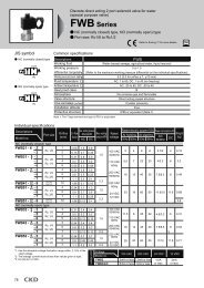
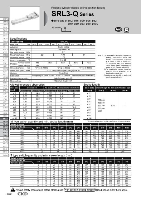
SCP*2CMK2CMA2SCMSCGSCA2SCSCKV2CA/OV2SSDCATMDC2MVCSMD2MSD*FC*STKULK*JSK/M2JSGJSC3USSDUSCJSB3LMBSTGSTS LLCSLCGLCMLCTLCYSTR2UCA2HCMHCA<strong>SRL3</strong>SRG3SRM3SRT3MRL2MRG2SM-25CAC4UCAC2RCC2MFCSHCGLCEndingSpecificationsDescriptionsBore sizemmActuationWorking fluidMax. working pressure MPaMin. working pressure MPaWithstanding pressure MPaAmbient temperatureCylinder sectionPort sizePosition locking unitStroke toleranceWorking piston speedCushionLubricationPosition locking mechanismHolding forcemmmm/sN<strong>SRL3</strong>-Qø12 ø16 ø20 ø25 ø32 ø40 ø50 ø63 ø800.2Double actingCompressed air0.70.151.055 to 600.1M5M5Allowable energy absorptionBore size(mm)ø12ø16ø20ø25ø32ø40ø50ø63ø80ø100Rc 1 /8Rc 1 /4Rc 1 /8Rc 3 /8Rc 1 /2ø100+ 2.0+ 2.5+ 3.00 (up to 1000)0 (up to 3000)0 (up to 5000)50 to 200 (standard port piping) (note 1)Air cushionNot required (Use turbine oil Class 1 ISOVG32 if lubricated. Lubricate continuously if lubricated. )Installation on guard RMaximum thrust x 0.7CushionedNo cushionWith shock absorber (initial setpoint)Allowable energy absorption (J) Cushion mm stroke (mm) Allowable energy absorption (J) Absorbed energy (J) Valid mm stroke (mm)0.030.220.591.402.574.279.1317.4406714.519.222.220.923.523.924.929.645.845.80.0030.0070.0100.0150.0300.0500.0720.1380.3930.6222.42.45.710185086861431435.55.5791316.521212525M type switch quantity and min. stroke length (mm)Switch quantitySwitch model no.Bore size (mm)ø12ø16ø20ø25ø32ø40ø50ø63ø80ø100T type switch quantity and min. stroke length (mm)Switch quantitySwitch model no.Bore size (mm)ø12ø16ø20ø25ø32ø40ø50ø63ø80ø100M*V1010101010101515T*V55510101010101515125251M*H1010101010101515T*H55510101010101515<strong>Rodless</strong> <strong>cylinder</strong> double acting/position locking<strong>SRL3</strong>-Q SeriesBore size ø: ø12, ø16, ø20, ø25, ø32ø40, ø50, ø63, ø80, ø100JIS symbolM*V3030303030303030T*V45454545454545454545250502M*H7070707045454545T*H70707070505050505050M*V6060606060606060T*V8585858585858585858531001003M*H12012012012090909090T*H120120120120100100100100100100Stroke lengthBore size(mm)ø12ø16ø20ø25ø32ø40ø50ø63ø80ø100M*V9090909090909090T*V125125125125125125125125125125Note 1: (1)The speed of entry to the positionlocking mechanism must notexceed 500mm/s when operatingat a speed of 500 to 2000mm/s.For common port pipe, workingpiston speed varies depending onstroke length. Consult with <strong>CKD</strong>.(2)For deceleration method, install anexternal shock absorber or adeceleration circuit etc..(3)Apply grease to sliding section oflock lever periodically.Standard stroke length(mm)200,300400,500600,700800,9001000Max. stroke length(mm)5000Min. stroke length(mm)** The intermediate stroke can be manufactured in 1mm increments.41501504M*H170170170170135135135135T*H170170170170150150150150150150M*V5120120120120120120120120200200T*V1651651651651651651651651651655M*H220220220220180180180180T*H220220220220200200200200200200M*V6150150150150150150150150250250T*V20520520520520520520520520520561M*H270270270270225225225225T*H2702702702702502502502502502502032Always safety precautions before starting use With position locking function Read pages 2001 the to 2003.