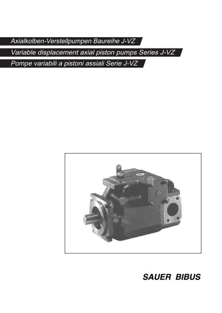
Variable displacement axial piston pumps Series J-VZ ... - Sauer Bibus
Variable displacement axial piston pumps Series J-VZ ... - Sauer Bibus
Variable displacement axial piston pumps Series J-VZ ... - Sauer Bibus

Create successful ePaper yourself
Turn your PDF publications into a flip-book with our unique Google optimized e-Paper software.
Axialkolben-Verstellpumpen<strong>Variable</strong> <strong>displacement</strong> <strong>axial</strong> <strong>piston</strong> <strong>pumps</strong>Pompe variabili a <strong>piston</strong>i assialiBaureihe J-<strong>VZ</strong><strong>Series</strong> J-<strong>VZ</strong>Serie J-<strong>VZ</strong>Allgemeine Beschreibung . General description . Descrizione generaleDie SAUER-BIBUS Axialkolben-Verstellpumpender Baureihe J-<strong>VZ</strong> in Schrägscheibenbauartsind Einheiten für den offenenKreislauf mit verstellbarem oder geregeltemFördervolumen. Sie wurden speziellfür den Einsatz in stationären Anwendungenentwickelt.Besondere Merkmale- niedrige Geräuschwerte über den gesamtenDruckbereich durch gezielte Triebwerks-und Lagerentwicklung- ein marktgerechtes Reglerprogrammführt zu Energieersparnis durch optimaleAnpassung von Druck- und Förderstromund zu einem geringeren Kostenaufwanddurch Wegfall von Ventilen in bisher ausgeführtenHydraulikkreisen- die niedrige Verlustleistung der Einheiten,insbesondere im Nullhubbetrieb, führt zueiner geringeren Ölerwärmung und damitzu kompakten, platzsparendenBehälterabmessungen- kurze Regelzeiten und hohe Wiederholgenauigkeitenbei der Druck- und Förderstromregelungreduzieren Zykluszeitenvon Maschinen bei gleichzeitigerErhöhung der Zuverlässigkeit- einfache Erstbefüllung der Einheit mitdem Betriebsmedium im betriebsbereiten,verrohrten Zustand, ohne Abbau derLeckölleitung durch zusätzlich verfügbareVerschlußschraube- eine mechanisch einstellbare Fördervolumenbegrenzungerlaubt die stufenloseAnpassung des Förderstroms an dieForderung einer Anwendung- kompakte und leichte Gesamtkonstruktion- auch als Durchtriebspumpen lieferbarThe SAUER-BIBUS variable <strong>displacement</strong><strong>axial</strong> <strong>piston</strong> <strong>pumps</strong>, series J-<strong>VZ</strong> swash plateconstruction, are suitable for open loopcircuits with adjustable or regulated deliveryflow. These units are specially designed foruse in industrial applications.Special Characteristics- low external noise levels across the entirepressure range because of speciallydeveloped mechanism and bearingdesign- a comprehensive control selectionassures energy saving through optimaladjustment of pressure and delivery flow,lower unit cost because valves used inconventional hydraulic circuit designs aresuperfluous in this system- low oil heat generation because of lowdissipation loss, especially during deadhead operation, facilitates compactspacesaving reservoir design- fast response time and high repetitionaccuracy for pressure and delivery flow,reducing machine cycle times while at thesame time improving reliability- simple first filling with hydraulic mediumin mounted state without dismantling anylines, because of an extra locking screw- mechanical adjustment to allowadjustment of delivery flow to suit theapplication- compact and light-weight construction- available also as through-shaft-<strong>pumps</strong>Bild / Fig. 1Le pompe variabili a <strong>piston</strong>i assiali SAU-ER-BIBUS serie J-<strong>VZ</strong> a piatto inclinato sonocomponenti per circuito aperto a cilindratavariabile o regolabile. Sono statespecificatamente concepite per l´impiego inapplicazioni industriali.Caratteristiche specifiche- rumorosità estremamente contenuta intutto il campo di pressione grazie allaprogettazione mirata del rotore e dellasupportazione- un´esauriente gamma di controlli assicurarisparmio di energia attraverso laregolazione ottimale di pressione eportata e porta a un costo di realizzazioneinferiore poichè valvole utilizzate in circuiticonvenzionali diventa no superflue inquesto sistema- bassa generazione di calore grazie adissipazioni minime, specialmente in fasedi compensazione; ciò porta a serbatoipiù piccoli- tempo di risposta breve con elevataprecisione nella ripetizione dei valori dipressione e portata, con conseguenteriduzione del ciclo macchina emiglioramento dell´affidabilità- facile riempimento della pompa con ilfluido in condizione di tubazioni collegatesenza disconnettere il drenaggio, grazieall´apposito foro con tappo di chiusura- il limitatore meccanico di cilindratapermette una regolazione continua conadattamento alle portate richiestedall´utilizzo- Esecuzione leggera e compatta3
Axialkolben-Verstellpumpen<strong>Variable</strong> <strong>displacement</strong> <strong>axial</strong> <strong>piston</strong> <strong>pumps</strong>Pompe variabili a <strong>piston</strong>i assialiBaureihe J-<strong>VZ</strong><strong>Series</strong> J-<strong>VZ</strong>Serie J-<strong>VZ</strong>Regel- und Verstellorgane . Control devices . Dispositivi di regolazioneBezeichnungDescriptionDenominazioneTypTypeTipoSinnbildSymbolSimboloKennlinieCharacteristicCurva caratteristicaNullhubdruckregler- mech. einstellbarPressure compensator control- mechanical adjustmentRegolatore ad annullamento di portata- registr. meccanicaALPSQP 2Nullhubdruckregler- hydr. fernsteuerbarRemote pressure compensator control- hydraulic remote control by pilot relief valveRegolatore ad annullamento di portata- pilotaggio idr. a distanzaA-RCLPSQP 2kombinierter Nullhubdruck- und FörderstromreglerSAXPQCombined flow and pressure compensator controlRegolatore di portata combinato con annullamentodi portataLSP 2Zweistufen-Nullhubdruckregler, hydr. umschaltbar,kombiniert mit FördervolumenumschaltungCombined control pressure and <strong>displacement</strong> withsystem pressureRegolatore ad annullamento di portata a due stadi,commutazione idr., con cambio di cilindrataCHLPSQP 2Zweistufen-Nullhubdruckregler, elekt. umschaltbar,kombiniert mit FördervolumenumschaltungCombined control pressure and <strong>displacement</strong>with solenoid valveRegulatore ad annullamento di portata a due stadi,commutazione elettr., con cambio di cilindrataCJaA BP TPQP 2LSQP 2QP 2Tabelle / Table / Tabella 1:4
Axialkolben-Verstellpumpen<strong>Variable</strong> <strong>displacement</strong> <strong>axial</strong> <strong>piston</strong> <strong>pumps</strong>Pompe variabili a <strong>piston</strong>i assialiBaureihe J-<strong>VZ</strong><strong>Series</strong> J-<strong>VZ</strong>Serie J-<strong>VZ</strong>Kenngrößen . Operating data . Dati caratteristiciBenennung Formelz. Einheit Baugröße . Size . GrandezzaDescription Symbol UnitDescrizioneSimbolo Unità di mis. 50 63 80 100 130Befestigungsart; stirns. FlanschbefestigungType of attachment - -Flangia di fissaggio ant.Geometrisches FördervolumenDisplacement Vg cm 3CilindrataGeometr. Förderstrom n=1500 min -1Outlet flow q V2l/minPortata aDrehrichtung, GewichtSense of rotation, Weight - -Senso di rotazione, pesoDrehzahlbereichnRange of speedsminnGamma di velocitàmaxmin -1EingangsdruckbereichInlet pressure range p 1,minbar absCampo di pressione in asp.LeckstromdruckbereichCase pressure range p vd, maxbarCampo di pressione drenaggioAusgangsdruckbereich (DIN 24312)Outlet pressure range (DIN 24312)Campo press. in mandata (din 24312)p 2,n- Nenndruck . nominal pressure .Pressione nominalep 2, pbar- Höchstdruck . max. pressure . Press. max.Viscositätsbereich am EingangυViscosity range1, minυGamma di viscosità1, maxmm 2 /sDruckflüssigkeitstemp.-bereich am EingangθHydraulic fluid temperature range 1, f. minθGamma di temperatura del fluido idr. 1, f. max°CISO 3019/250,2 63,0 79,6 104,6 135,975,3 94,5 119,4 156,9 203,9rechtsdrehendclockwisedestro50018000,80,35 für Dauerbetrieb, 1,0 kurzzeitig0,35 for cont. operation, 1,0 momentary0,35 in esercizio continuo, 1,0 intermitti280 210350* 250*15400060Reinheitsgrad der DruckflüssigkeitFluid cleanliness - -Grado di pulizia del fluidoDruckflüssigkeitHydraulic fluid - -Fluido idraulicoFilterung . Filtering . Filtrazione- saugseitig . suction . in aspirazione - µm- rücklaufseitig . return . sul ritornoFüllmenge für ErstbefüllungOil volumes for first filling - lOlio di primo riempimento18/14 nach CETOP RP 70 H oder 9 nach NAS 1638 und besser,insbesondere bei hohen Belastungen und Lebensdaueranforderungen18/14 to CETOP RP 70 H or 9 to NAS 1638 or better,especially at high loads and high life expectancy requirements.18/14 secondo CETOP RP 70 H oppure 9 secondo NAS 1638 o migliori,in particolare con carichi gravosi o se viene richiesta una durata elevantaauf Mineralölbasis nach DIN 51524 u. DIN 51525, andere Flüssigkeiten auf Anfrage, bei Bedarf bitteDruckflüssigkeitsempfehlung anfordern . For mineral oil base DIN 51524 and DIN 51525, other fluids onrequest, please ask for hydraulic fluid recommendations if required . a base minerale secondo DIN51524 e DIN 51525, altri fluidi a richiesta, in caso di bisogno preghiamo esigere fluidi consigliati;Viscosität . viscosity . viscosità:ν min= 7 mm 2 /sν empf.= 12...54 mm 2 /s Betriebsviskosität empfohlen . rated viscosity . Viscosità di esercizio consigliataν max= 800 mm 2 /s kurzz. bei Start, wenige Sek. . intermittent, cold start . Viscosità di avviamento, per pochi secondi15025 absolut / absolute / assoluti1,3 1,4 1,5 1,6 1,6*10% eines Zyklus, max. 6 sek. / 10% of one cycle, max. 6 sec. / 10% di ciclo, massimo 6 sec Tabelle / Table / Tabella 2:5
Axialkolben-Verstellpumpen<strong>Variable</strong> <strong>displacement</strong> <strong>axial</strong> <strong>piston</strong> <strong>pumps</strong>Pompe variabili a <strong>piston</strong>i assialiBaureihe J-<strong>VZ</strong><strong>Series</strong> J-<strong>VZ</strong>Serie J-<strong>VZ</strong>Drehrichtung und Masse . Sense of rotation and weight . Senso di rotazione e pesoBaugröße Lage d. Arbeits- Drehrichtung: Sense of rotation: Senso di rotazione:Size anschlüsse R=rechtsdrehend R=clockwise R=destroGrandezza Masse m [kg] Weight m [kg] Peso m [kg]Port Positionbei Verwendung des Reglers . for use with controls . con l´utilizzo dei regolatoriPosizionedelle bocche A A-RC SA CH CJ50 radial 40 40 40 42 4263 radial 47 47 47 49 4980 radial 55 55 55 57 57100 radial 75 75 75 77 77130 radial 105 105 105 107 107Tabelle / Table / Tabella 3:Nullhubdruckeinstellbereich . Adjustable pressure range . Campo di registrazione della press. di azz.ReglerControlsRegolatoreAA-RCSACHCJA2A3A4A4-RCSA2*SA3*SA4*C2*HC*2HC*3HC*4HC2*JC*2JC*3JC*4JNullhubdruckeinstellbereich p 2. Adjustable pressure range p 2Campo di registrazione press. di azz. p 2/ barBaugröße . Size . Grandezza50 63 80 100 13015 ... 14035 ... 21035 ... 280 –35 ... 280 35...21015 ... 140 –35 ... 210 –35 ... 280 –15 ... 140 –15 ... 140 –35 ... 210 –35 ... 280 –15 ... 140 –15 ... 140 –35 ... 210 –35 ... 280 –Tabelle / Table / Tabella 4:6
Axialkolben-Verstellpumpen<strong>Variable</strong> <strong>displacement</strong> <strong>axial</strong> <strong>piston</strong> <strong>pumps</strong>Pompe variabili a <strong>piston</strong>i assialiBaureihe J-<strong>VZ</strong><strong>Series</strong> J-<strong>VZ</strong>Serie J-<strong>VZ</strong>Typenschlüssel bei Verwendung von . Model code . Chiave di ordinazione con l´utilizzo delRegler A . Control A . Regolatore AJ - V Z * * A * * * - * *Baureihe<strong>Series</strong> = J-<strong>VZ</strong>SerieBaugröße . Size . Grandezza50,2 cm 3 = 5063,0 cm 3 = 6379,6 cm 3 = 80104,6 cm 3 = 100135,9 cm 3 = 130Regler . Control . Regolatoremech. einstellb. Nullhubdruckregler = Apressure compensator controlcompensatore di press. a registrazione mecc.Druckeinstellbereich (siehe Tabelle 4)Pressure adjustment range (see table 4)Campo di regolazione press. (vedi tabella 4)Ausführungskennzeichen (Stand bei Druck)Design NumberN° del tipoJ - <strong>VZ</strong> 50 = 10J - <strong>VZ</strong> 63 = 10J - <strong>VZ</strong> 80 = 10J - <strong>VZ</strong> 100 = 10J - <strong>VZ</strong> 130 = 10Lage der Arbeitsanschlüsse (siehe Tabelle 3)Port position (see table 3)Posizione delle bocche (vedi tabella 3)radial . laterali = XDrehrichtung (siehe Tabelle 3)Sense of rotation (see table 3)Senso di rotazione (vedi tabella 3)rechtsdrehend . clockwise . destro = R15 bar ............. 140 bar = 235 bar ............. 210 bar = 335 bar ............. 280 bar = 4** J-<strong>VZ</strong> 50, 63, 80, 100Regler A-RC . Control A-RC . Regolatore A-RCJ - V Z * * A * * * - * * R CBaureihe<strong>Series</strong> = J-<strong>VZ</strong>SerieBaugröße . Size . Grandezza50,2 cm 3 = 5063,0 cm 3 = 6379,6 cm 3 = 80104,6 cm 3 = 100135,9 cm 3 = 130Regler . Control . RegolatoreNullhubdruckregler hydr. fernsteuerbarremote pressure compensator controlRegolatore ad annullamento di portatapilotaggio idr. a distanza= A-RCAusführungskennzeichen (Stand bei Druck)Design NumberN° del tipoJ - <strong>VZ</strong> 50 = 10J - <strong>VZ</strong> 63 = 10J - <strong>VZ</strong> 80 = 10J - <strong>VZ</strong> 100 = 10J - <strong>VZ</strong> 130 = 10Lage der Arbeitsanschlüsse (siehe Tabelle 3)Port position (see table 3)Posizione delle bocche (vedi tabella 3)radial . laterali = XDruckeinstellbereich (siehe Tabelle 4)Pressure adjustment range (see table 4)Campo di regolazione press. (vedi tabella 4)35 bar ............. 280 bar = 4Drehrichtung (siehe Tabelle 3)Sense of rotation (see table 3)Senso di rotazione (vedi tabella 3)rechtsdrehend . clockwise . destro = R7
Axialkolben-Verstellpumpen<strong>Variable</strong> <strong>displacement</strong> <strong>axial</strong> <strong>piston</strong> <strong>pumps</strong>Pompe variabili a <strong>piston</strong>i assialiBaureihe J-<strong>VZ</strong><strong>Series</strong> J-<strong>VZ</strong>Serie J-<strong>VZ</strong>Typenschlüssel bei Verwendung von . Model code . Chiave di ordinazione con l´utilizzo delRegler SA . Control SA . Regolatore SAJ - V Z * * S A * * * * - * *Baureihe<strong>Series</strong> = J-<strong>VZ</strong>SerieBaugröße . Size . Grandezza50,2 cm 3 = 5063,0 cm 3 = 6379,6 cm 3 = 80104,6 cm 3 = 100135,9 cm 3 = 130Regler . Control . Regolatorekomb. Druck- und Förderstromregler = SAflow and pressure compensator controlRegolatore combin. di pressione e portataDruckeinstellbereich (siehe Tabelle 4)Pressure adjustment range (see table 4)Campo di regolazione press. (vedi tabella 4)15 bar ............. 140 bar = 235 bar ............. 210 bar = 335 bar ............. 280 bar = 4** J-<strong>VZ</strong> 50, 63, 80, 100Ausführungskennzeichen (Stand bei Druck)Design NumberN° del tipoJ - <strong>VZ</strong> 50 = 10J - <strong>VZ</strong> 63 = 10J - <strong>VZ</strong> 80 = 10J - <strong>VZ</strong> 100 = 10Lage der Arbeitsanschlüsse (siehe Tabelle 3)Port position (see table 3)Posizione delle bocche (vedi tabella 3)radial . laterali = XDrehrichtung (siehe Tabelle 3)Sense of rotation (see table 3)Senso di rotazione (vedi tabella 3)rechtsdrehend . clockwise . destro = RDifferenzdruck . Differential press. . Differenziale di press.7 bar = A14 bar = B21 bar = CRegler CH . Control CH . Regolatore CHJ - V Z * * C * * * H * - * *Baureihe<strong>Series</strong> = J-<strong>VZ</strong>SerieBaugröße . Size . Grandezza50,2 cm 3 = 5063,0 cm 3 = 6379,6 cm 3 = 80104,6 cm 3 = 100135,9 cm 3 = 130Regler . Control . RegolatoreZweistufen- Nullhubdruckregler = CHhydr. umschaltbar mit FördervolumenumschaltungCombined control press. and displ. with system press.Compensatore di press. a due stadi commutabileidraulicamente con commutazione di portataDruckeinstellbereich (siehe Tabelle 4)Pressure adjustment range (see table 4)Campo di regolazione press. (vedi tabella 4)Stufe p2,I . stage p2,I . stadio 2,I15 bar ............. 140 bar = 2Ausführungskennzeichen (Stand bei Druck)Design NumberN° del tipoJ - <strong>VZ</strong> 50 = 10J - <strong>VZ</strong> 63 = 10J - <strong>VZ</strong> 80 = 10J - <strong>VZ</strong> 100 = 10Lage der Arbeitsanschlüsse (siehe Tabelle 3)Port position (see table 3)Posizione delle bocche (vedi tabella 3)radial . laterali = XDrehrichtung (siehe Tabelle 3)Sense of rotation (see table 3)Senso di rotazione (vedi tabella 3)rechtsdrehend . clockwise . destro = RStufe p2,II . stage p2,II . stadio 2,II15 bar ............. 140 bar = 235 bar ............. 210 bar = 335 bar ............. 280 bar = 48
Axialkolben-Verstellpumpen<strong>Variable</strong> <strong>displacement</strong> <strong>axial</strong> <strong>piston</strong> <strong>pumps</strong>Pompe variabili a <strong>piston</strong>i assialiBaureihe J-<strong>VZ</strong><strong>Series</strong> J-<strong>VZ</strong>Serie J-<strong>VZ</strong>Typenschlüssel bei Verwendung von . Model code . Chiave di ordinazione con l´utilizzo delRegler CJ . Control CJ . Regolatore CJJ - V Z * * C * * * J * * - * *Baureihe<strong>Series</strong> = J-<strong>VZ</strong>SerieBaugröße . Size . Grandezza50,2 cm 3 = 5063,0 cm 3 = 6379,6 cm 3 = 80104,6 cm 3 = 100135,9 cm 3 = 130Regler . Control . RegolatoreZweistufen- Nullhubdruckregler = CJelektr. umschaltbar mit FördervolumenumschaltungCombined control press. and displ. with solenoid valveCompensatore di press. a due stadi commutabileelettricamente con commutazione di portataDruckeinstellbereich (siehe Tabelle 4)Pressure adjustment range (see table 4)Campo di regolazione press. (vedi tabella 4)Stufe p2,I . stage p2,I . stadio 2,I15 bar ............. 140 bar = 2Stufe p2,II . stage p2,II . stadio 2,II15 bar ............. 140 bar = 235 bar ............. 210 bar = 335 bar ............. 280 bar = 4Ausführungskennzeichen (Stand bei Druck)Design NumberN° del tipoJ - <strong>VZ</strong> 50 = 10J - <strong>VZ</strong> 63 = 10J - <strong>VZ</strong> 80 = 10J - <strong>VZ</strong> 100 = 10Lage der Arbeitsanschlüsse (siehe Tabelle 3)Port position (see table 3)Posizione delle bocche (vedi tabella 3)radial . laterali = XMagnetspannungen . Solenoid ratings . Voltaggio dei magneti12 Volt DC = N24 Volt DC = P110 Volt/50 Hz AC = C220 Volt/50 Hz AC = Dandere Spannungen auf Anfrage . other voltages on request .altri voltaggi a richiestaDrehrichtung (siehe Tabelle 3)Sense of rotation (see table 3)Senso di rotazione (vedi tabella 3)rechtsdrehend . clockwise . destro = R9
Axialkolben-Verstellpumpen<strong>Variable</strong> <strong>displacement</strong> <strong>axial</strong> <strong>piston</strong> <strong>pumps</strong>Pompe variabili a <strong>piston</strong>i assialiBaureihe J-<strong>VZ</strong><strong>Series</strong> J-<strong>VZ</strong>Serie J-<strong>VZ</strong>Kennlinien . Characteristics . Curve caratteristicheMeßbedingungen: n = 1500 min -1 Measuring conditions: n = 1500 min -1 Condizioni di misurazione: n = 1500 min -1θ 1,f= 50°C, Mineralöl ISO VG 32 θ 1,f= 50°C, mineral oil ISO VG 32 θ 1,f= 50°C, olio minerale ISO VG 32Dynamisches Verhalten des Nullhubdruckreglers A . Dynamic performance of control A .Prestazione dinamica del compensatore ABaugröße Abregelzeit Aufregelzeit DruckspitzeSize Response time Pressure peakGrandezza Tempo di risposta Picco di press.t 1, [s] t 2, [s] p s, [bar]50 0,020 0,045 60...10063 0,025 0,050 60...10080 0,025 0,060 70...110100 0,030 0,060 70...120130 0,030 0,070 70...120Tabelle / Table / Tabella 5:Einstellbereich . Adjusting rangeCampo di regolazionep 2bar∆p ≤ 5 barBild / Fig. 2:Pt 1t 250 bar280 bar50 barp 2barp sLSBild / Fig. 3:Bild / Fig. 4:10
Axialkolben-Verstellpumpen<strong>Variable</strong> <strong>displacement</strong> <strong>axial</strong> <strong>piston</strong> <strong>pumps</strong>Pompe variabili a <strong>piston</strong>i assialiBaureihe J-<strong>VZ</strong><strong>Series</strong> J-<strong>VZ</strong>Serie J-<strong>VZ</strong>Geräuschmessungen (Kennlinie Lp - p 2) . Noise level (characteristic Lp - p 2) . Livello di rumorosità (curva Lp - p 2)gemessen im Schallmeßraum, Meßabstand 1m . measured in a sound measuring room, distance 1m . misurato in camera anecoica, alla distanza di 1m757570q v2 max70L pdB(A)65q v2 Null/zero6060555550500 50 100 150 200 250 280 3000 50 100 150 200 250 280 300p 2barp 2barBild / Fig. 5: Baugröße . Model . Grandezza J-<strong>VZ</strong> 50 Bild / Fig. 6: Baugröße . Model . Grandezza J-<strong>VZ</strong> 637580L pdB(A)7065q v2 Null/zeroq v2 maxq v2 Null/zeroq v2 Null/zero65q v2 max6060555550500 50 100 150 200 250 280 3000 50 100 150 200 250 280 300p 2barp 2barBild / Fig. 7: Baugröße . Model . Grandezza J-<strong>VZ</strong> 80 Bild / Fig. 8: Baugröße . Model . Grandezza J-<strong>VZ</strong> 1008075L pdB(A)L pdB(A)65757070L pdB(A)656055500 50 100 150 200 250 280 300p 2barBild / Fig. 9: Baugröße . Model . Grandezza J-<strong>VZ</strong> 13011
Axialkolben-Verstellpumpen<strong>Variable</strong> <strong>displacement</strong> <strong>axial</strong> <strong>piston</strong> <strong>pumps</strong>Pompe variabili a <strong>piston</strong>i assialiBaureihe J-<strong>VZ</strong><strong>Series</strong> J-<strong>VZ</strong>Serie J-<strong>VZ</strong>Wirkungsgrad, Förderstrom, Leistung (Kennlinie η, q v2, e, P 2-p 2) . Performance characteristic (eff. η, q v2, e,input power P 2-p 2) . Rendimento, portata, potenza (Rendimento η, Portata q v2, e, Potenza in entrataP 2-p 2)100100Wirkungsgrad . Efficiency . Rendimento η%9080706050403020100vv2,p 20 35 70 105 140 175 210 245 280ηq ebarη t80q vl/minP 2kW6040200403020100Wirkungsgrad . Efficiency . Rendimento η%η vq v2, e100p 29080706050η t403020100p qv2 max8060402000 35 70 105 140 175 210 245 280barq vl/minP 2kWp qv2 maxBild / Fig. 13: Baugröße . Model . Grandezza J-<strong>VZ</strong> 10050403020100Bild / Fig. 10: Baugröße . Model . Grandezza J-<strong>VZ</strong> 50 Bild / Fig. 11: Baugröße . Model . Grandezza J-<strong>VZ</strong> 63p qv2 max2p 2100100η v η9090vη tη t80807070q v2, e q60120 6060v2, e18050p qv2 max100 50501504080 40401203060 3030902040 20206010p qv2 max30 101020 10103000 0000 35 70 105 140 175p210 245 2800 35 70 105 140 175 210 245 280barbarBild / Fig. 12: Baugröße . Model . Grandezza J-<strong>VZ</strong> 801009080η tq v2, e70210 10560180 6050150 5040120 403090 302060 2000 35 70 105 140 175 2100 0η vp 2barWirkungsgrad . Efficiency . Rendimento η%Wirkungsgrad . Efficiency . Rendimento η%q vl/minP 2kWq vl/minP 2kWWirkungsgrad . Efficiency . Rendimento η%q vl/minP 2kW9075604530150Bild / Fig. 14: Baugröße . Model . Grandezza J-<strong>VZ</strong> 13012
Axialkolben-Verstellpumpen<strong>Variable</strong> <strong>displacement</strong> <strong>axial</strong> <strong>piston</strong> <strong>pumps</strong>Pompe variabili a <strong>piston</strong>i assialiBaureihe J-<strong>VZ</strong><strong>Series</strong> J-<strong>VZ</strong>Serie J-<strong>VZ</strong>Externer Leckstrom (q vd- p 2) . External leakage flow (q vd- p 2) . Drenaggio esterno (q vd- p 2)q vdl/min1098765431500 min -11800 min -1 109Reglerfelder 3,4 .Reglerfelder 3,4 .8Compensator . MolleCompensatorq . Mollev2 Null/zero q v2 Null/zero765Reglerfelder 1,2 .4Reglerfelder 1,2 .q Compensator . Compensator . Mollev2 Null/zero Molle3q v2 maxq vdl/minq v2 Null/zeroq v2 max2121000 35 70 105 140 175 210 245 2800 35 70 105 140 175 210 245 280p 2barp 2barBild / Fig. 15: Baugröße . Model . Grandezza J-<strong>VZ</strong> 50 Bild / Fig. 16: Baugröße . Model . Grandezza J-<strong>VZ</strong> 63q vdl/min10987654321q v2 Null/zeroReglerfelder 3,4 .Compensator . Molleq v2 Null/zeroReglerfelder 1,2 .Compensator . Molleq v2 max00 35 70 105 140 175 210 245 280p 2barBild / Fig. 17: Baugröße . Model . Grandezza J-<strong>VZ</strong> 80q vdl/min10987654321q v2 maxq v2 Null/zero Reglerfelder 3,4 .Compensator . Molle00 35 70 105 140 175 210 245 280p 2barBild / Fig. 18: Baugröße . Model . Grandezza J-<strong>VZ</strong> 1002018q vdl/min161412108q v2 Null/zeroReglerfelder 3,4 .Compensator . Molle642q v2 max00 35 70 105 140 175 210p 2barBild / Fig. 19: Baugröße . Model . Grandezza J-<strong>VZ</strong> 13013
Axialkolben-Verstellpumpen<strong>Variable</strong> <strong>displacement</strong> <strong>axial</strong> <strong>piston</strong> <strong>pumps</strong>Pompe variabili a <strong>piston</strong>i assialiNullhubleistung (Pq v Null- p 2) . Dead head horsepower characteristic (Pq v zero- p 2) .Potenza dispersa in compensazione (Pq v zero- p 2)Baureihe J-<strong>VZ</strong><strong>Series</strong> J-<strong>VZ</strong>Serie J-<strong>VZ</strong>101500 min -11800 min -110998787Reglerfelder 3,4 .Compensator . MolleP qv Null/zerokW65432Reglerfelder 3,4 .Compensator . MolleReglerfelder 1,2 .Compensator . MolleP qv Null/zerokW65432Reglerfelder 1,2 .Compensator . Molle1100 35 70 105 140 175 210 245 280p 2barBild / Fig. 20: Baugröße . Model . Grandezza J-<strong>VZ</strong> 500 0 35 70 105 140 175 210 245 280p 2barBild / Fig. 21: Baugröße . Model . Grandezza J-<strong>VZ</strong> 6310109987Reglerfelder 3,4 .Compensator . Molle87Reglerfelder 3,4 .Compensator . MolleP qv Null/zerokW65432Reglerfelder 1,2 .Compensator . MolleP qv Null/zerokW65432110 0 35 70 105 140 175 210 245 280p 2barBild / Fig. 22: Baugröße . Model . Grandezza J-<strong>VZ</strong> 800 0 35 70 105 140 175 210 245 280p 2barBild / Fig. 23: Baugröße . Model . Grandezza J-<strong>VZ</strong> 10010987Reglerfelder 3,4 .Compensator . MolleP qv Null/zerokW6543210 0 35 70 105 140 175 210p 2barBild / Fig. 24: Baugröße . Model . Grandezza J-<strong>VZ</strong> 13014
Axialkolben-Verstellpumpen<strong>Variable</strong> <strong>displacement</strong> <strong>axial</strong> <strong>piston</strong> <strong>pumps</strong>Pompe variabili a <strong>piston</strong>i assialiBaureihe J-<strong>VZ</strong><strong>Series</strong> J-<strong>VZ</strong>Serie J-<strong>VZ</strong>Geräteabmessungen . Installation dimensions . DimensioniBild / Fig. 25: Baugröße . Model . Grandezza J-<strong>VZ</strong> 50M 1227 tief/deep/prof.22469,85SauganschlußInlet portAspirazioneø 38,135,71270FörderstromeinstellschraubeFlow adjustment screwVite di registro cil. max.max. 120 121A-RC Regler/Control/RegolatoreSA Regler/Control/RegolatoreA Regler/Control/Regolatore148 55,5381473 133X1227552,37ø 25,4A 8 x 7 x 38ø 100 –0,050ø140M 1022 tief/deep/prof.26,1922615,510ø 25 ±0,006528 –0,20258210Öffnung für Erstbefüllungvor InbetriebnahmePriming portForo di preriempimento14878A-RC Regler/Control/RegolatoreLeckölanschlußCase drain portForo di drenaggioM 22 x 1,5SA Regler/Control/RegolatoreARegler/Control/RegolatoreEinstellschraube für NullhubdruckPressure adjustment screwVite di registro press. max.max. 120ARegler/Control/RegolatoreEinstellschraubefür DifferenzdruckFörderstromreglerDifferential pressureadjustment screwVite di registro ∆pDifferenzdruckanschlußLoad pressure conn.Attacco pressione diff.7/16 - 20 UNF - 2BEinstellschraubefür NullhubdruckPressure adjustment screwVite di registro pressione max.93210,541SA Regler/Control/RegolatoreSauganschlußInlet portAspirazione1 1/2“ 3000 PSISAE J 5187272Ansicht / View / Vista XDruckanschlußOutlet portMandata1“ 3000 PSISAE J 518bis Mitte Pumpeup to middle of pumpdall´asse pompa249,5Einstellschraube fürDifferenzdruckDifferential pressureadjustment screwVite di registro ∆pFernsteueranschlußRemote control conn.Attacco pilotaggio a dist.7/16 - 20 UNF - 2B41A-RC Regler/Control/Regolatore15
Axialkolben-Verstellpumpen<strong>Variable</strong> <strong>displacement</strong> <strong>axial</strong> <strong>piston</strong> <strong>pumps</strong>Pompe variabili a <strong>piston</strong>i assialiBaureihe J-<strong>VZ</strong><strong>Series</strong> J-<strong>VZ</strong>Serie J-<strong>VZ</strong>Geräteabmessungen . Installation dimensions . DimensioniBild / Fig. 26: Baugröße . Model . Grandezza J-<strong>VZ</strong> 50216CJRegler/Control/Regolatore219 max 121CH Regler/Control/Regolatore75X275256216216.5228Ansicht / View / Vista X16
Axialkolben-Verstellpumpen<strong>Variable</strong> <strong>displacement</strong> <strong>axial</strong> <strong>piston</strong> <strong>pumps</strong>Pompe variabili a <strong>piston</strong>i assialiBaureihe J-<strong>VZ</strong><strong>Series</strong> J-<strong>VZ</strong>Serie J-<strong>VZ</strong>Geräteabmessungen . Installation dimensions . DimensioniBild / Fig. 27: Baugröße . Model . Grandezza J-<strong>VZ</strong> 63M 1227 tief/deep/prof.24369,85SauganschlußInlet portAspirazioneø 38,135,71289FörderstromeinstellschraubeFlow adjustment screwVite di registro cil. max.A-RC Regler/Control/Regolatoremax. 126 127SA Regler/Control/RegolatoreA Regler/Control/Regolatore166 681445°45°78 138X12780ø 25,452,3745A 8 x 7 x 45ø 125 –0,0630ø 160M 1022 tief/deep/prof.26,1924527716,510ø 32 +0,018 +0,00235 –0,20Öffnung für Erstbefüllungvor InbetriebnahmePriming portForo di preriempimento22916489A-RC Regler/Control/RegolatoreLeckölanschlußCase drain portForo di drenaggioM 26 x 1,5ARegler/Control/RegolatoreSA Regler/Control/RegolatoreEinstellschraube für NullhubdruckPressure adjustment screwVite di registro press. max.Einstellschraubefür DifferenzdruckFörderstromreglerDifferential pressureadjustment screwVite di registro ∆pmax. 118ARegler/Control/RegolatoreDifferenzdruckanschlußLoad pressure conn.Attacco pressione diff.7/16 - 20 UNF - 2BEinstellschraubefür NullhubdruckPressure adjustment screwVite di registro pressione max.229,59538SA Regler/Control/RegolatoreSauganschlußInlet portAspirazione1 1/2“ 3000 PSISAE J 5187575DruckanschlußOutlet portMandata1“ 3000 PSISAE J 518bis Mitte Pumpeup to middle of pumpdall´asse pompa268,5Einstellschraube fürDifferenzdruckDifferential pressureadjustment screwVite di registro ∆pAnsicht / View / Vista X38FernsteueranschlußRemote control conn.Attacco pilotaggio a dist.7/16 - 20 UNF - 2BA-RC Regler/Control/Regolatore17
Axialkolben-Verstellpumpen<strong>Variable</strong> <strong>displacement</strong> <strong>axial</strong> <strong>piston</strong> <strong>pumps</strong>Pompe variabili a <strong>piston</strong>i assialiBaureihe J-<strong>VZ</strong><strong>Series</strong> J-<strong>VZ</strong>Serie J-<strong>VZ</strong>Geräteabmessungen . Installation dimensions . DimensioniBild / Fig. 28: Baugröße . Model . Grandezza J-<strong>VZ</strong> 63235CJRegler/Control/Regolatore226 max127CH Regler/Control/Regolatore80X294275235219.5124 max231Ansicht / View / Vista X18
Axialkolben-Verstellpumpen<strong>Variable</strong> <strong>displacement</strong> <strong>axial</strong> <strong>piston</strong> <strong>pumps</strong>Pompe variabili a <strong>piston</strong>i assialiBaureihe J-<strong>VZ</strong><strong>Series</strong> J-<strong>VZ</strong>Serie J-<strong>VZ</strong>Geräteabmessungen . Installation dimensions . DimensioniBild / Fig. 29: Baugröße . Model . Grandezza J-<strong>VZ</strong> 80M 1227 tief/deep/prof.262,577,77SauganschlußInlet portAspirazioneø 50,842,88FörderstromeinstellschraubeFlow adjustment screwVite di registro cil. max.A-RC Regler/Control/Regolatoremax. 135 131SA Regler/Control/RegolatoreA Regler/Control/Regolatore177,5 6845°45°451483 143X13285ø 31,858,72A 10 x 9 x 45ø 125 –0,0630ø 160M 1028 tief/deep/prof.30,18262,5302,518,510ø 32 +0,018 +0,00235 –0,20Öffnung für Erstbefüllungvor InbetriebnahmePriming portForo di preriempimento242,5175,592,5LeckölanschlußCase drain portForo di drenaggioM 26 x 1,5A-RC Regler/Control/RegolatoreARegler/Control/RegolatoreSA Regler/Control/RegolatoreEinstellschraube für NullhubdruckPressure adjustment screwVite di registro press. max.max. 114ARegler/Control/RegolatoreEinstellschraubefür DifferenzdruckFörderstromreglerDifferential pressureadjustment screwVite di registro ∆pDifferenzdruckanschlußLoad pressure conn.Attacco pressione diff.7/16 - 20 UNF - 2BEinstellschraubefür NullhubdruckPressure adjustment screwVite di registro pressione max.24338SA Regler/Control/Regolatore100SauganschlußInlet portAspirazione2“ 3000 PSISAE J 5188080Ansicht / View / Vista XDruckanschlußOutlet portMandata1 1/4“ 3000 PSISAE J 518bis Mitte Pumpeup to middle of pumpdall´asse pompa38FernsteueranschlußRemote control conn.Attacco pilotaggio a dist.7/16 - 20 UNF - 2B282Einstellschraube fürDifferenzdruckDifferential pressureadjustment screwVite di registro ∆pA-RC Regler/Control/Regolatore19
Axialkolben-Verstellpumpen<strong>Variable</strong> <strong>displacement</strong> <strong>axial</strong> <strong>piston</strong> <strong>pumps</strong>Pompe variabili a <strong>piston</strong>i assialiBaureihe J-<strong>VZ</strong><strong>Series</strong> J-<strong>VZ</strong>Serie J-<strong>VZ</strong>Geräteabmessungen . Installation dimensions . DimensioniBild / Fig. 30: Baugröße . Model . Grandezza J-<strong>VZ</strong> 80248,5CJRegler/Control/Regolatore232 max131CH Regler/Control/RegolatoreX288.5248.5224,5121 max103236146Ansicht / View / Vista X20
Axialkolben-Verstellpumpen<strong>Variable</strong> <strong>displacement</strong> <strong>axial</strong> <strong>piston</strong> <strong>pumps</strong>Pompe variabili a <strong>piston</strong>i assialiBaureihe J-<strong>VZ</strong><strong>Series</strong> J-<strong>VZ</strong>Serie J-<strong>VZ</strong>Geräteabmessungen . Installation dimensions . DimensioniBild / Fig. 31: Baugröße . Model . Grandezza J-<strong>VZ</strong> 100M12x1.7527477.77SauganschlußInlet portAspirazioneø50.842.88FörderstromeinstellschraubeFlow adjustment screwVite di registro cil. max.157150A-RC Regler/Control/RegolatoreSA Regler/Control/Regolatore18899.545°45°145A Regler/Control/Regolatore13873ø11,11 +0,0250 x73CWX9258.720ø125 -0.063ø1‚Sø16092ø30M12x1.7530.183182741712.45ø44.45 -0.050+0.1349.3Öffnung für Erstbefüllungvor InbetriebnahmePriming portForo di preriempimento25516895A-RC Regler/Control/RegolatoreLeckölanschlußCase drain portForo di drenaggioM 26 x 1,5SA Regler/Control/RegolatoreARegler/Control/RegolatoreEinstellschraube für NullhubdruckPressure adjustment screwVite di registro press. max.115114 maxARegler/Control/RegolatoreEinstellschraubefür DifferenzdruckFörderstromreglerDifferential pressureadjustment screwVite di registro ∆pDifferenzdruckanschlußLoad pressure conn.Attacco pressione diff.7/16 - 20 UNF - 2BEinstellschraubefür NullhubdruckPressure adjustment screwVite di registro pressione max.255,538SA Regler/Control/RegolatoreSauganschlußInlet portAspirazione2“ Standard9090Ansicht / View / Vista XDruckanschlußOutlet portMandata1 1/4“ Standardbis Mitte Pumpeup to middle of pumpdall´asse pompa38294,5Einstellschraube fürDifferenzdruckDifferential pressureadjustment screwVite di registro ∆pA-RC Regler/Control/RegolatoreFernsteueranschlußRemote control conn.Attacco pilotaggio a dist.7/16 - 20 UNF - 2B21
Axialkolben-Verstellpumpen<strong>Variable</strong> <strong>displacement</strong> <strong>axial</strong> <strong>piston</strong> <strong>pumps</strong>Pompe variabili a <strong>piston</strong>i assialiBaureihe J-<strong>VZ</strong><strong>Series</strong> J-<strong>VZ</strong>Serie J-<strong>VZ</strong>Geräteabmessungen . Installation dimensions . DimensioniBild / Fig. 32: Baugröße . Model . Grandezza J-<strong>VZ</strong> 100286CJRegler/Control/Regolatore265 max 150CH Regler/Control/Regolatore145X32628692159116234,5246Ansicht / View / Vista X22
Axialkolben-Verstellpumpen<strong>Variable</strong> <strong>displacement</strong> <strong>axial</strong> <strong>piston</strong> <strong>pumps</strong>Pompe variabili a <strong>piston</strong>i assialiBaureihe J-<strong>VZ</strong><strong>Series</strong> J-<strong>VZ</strong>Serie J-<strong>VZ</strong>Geräteabmessungen . Installation dimensions . DimensioniBild / Fig. 33: Baugröße . Model . Grandezza J-<strong>VZ</strong> 130M20x227 tief/deep/prof.ø63.532550.8035.713253775017888.9FörderstromeinstellschraubeFlow adjustment screwVite di registro cil. max.165155+0,025ø11,11 0 x7322599.5730ø44.450 -0.05198.014949.3 +0.1380.880.8100X10069.85ø38.1ø152.40ø152.35+0.4ø21.380.8 80.8M12x1,7527 tief/deep/prof.2412.45Einstellschraube für NullhubdruckPressure adjustment screwVite di registro press. max.FernsteueranschlußRemote control conn.Attacco pilotaggio a dist.PT 1/4“327310217124149Drain port heightSauganschlußInlet portAspirazione2 1/2“ Standard9595Ansicht / View / Vista XDruckanschlußOutlet portMandata1 1/2“ StandardA Regler / Control /RegolatoreA-RC Regler / Control /RegolatoreÖffnung für Erstbefüllungvor InbetriebnahmeLeckölanschluß Priming portCase drain port Foro di preriempimentoForo di drenaggioM 26 x 1,523
Axialkolben-Verstellpumpen<strong>Variable</strong> <strong>displacement</strong> <strong>axial</strong> <strong>piston</strong> <strong>pumps</strong>Pompe variabili a <strong>piston</strong>i assialiBaureihe J-<strong>VZ</strong><strong>Series</strong> J-<strong>VZ</strong>Serie J-<strong>VZ</strong>Durchtriebspumpen mit SAE-Anschluß, Geräteabmessungen . Through drive <strong>pumps</strong> with SAEconnection size, Installation dimensions . Pompe ad albero passante con attaco SAE, dimensioniFBDEBFABild / Fig. 34:BaugrößeSizeJ-<strong>VZ</strong>50 J-<strong>VZ</strong>63 J-<strong>VZ</strong>80 J-<strong>VZ</strong>100 J-<strong>VZ</strong>130Grandezza SAE A SAE B SAE A SAE B SAE A SAE B SAE A SAE B SAE A SAE BA mm 294,5 302 313,5 321 329 336,5 358 417B mm SAE A: 106,4SAE B: 146C mm 11D mm+0,15SAE A: 85,83 0+0,15SAE B: 107,77 0E mm+0,026SAE A: 82,60 0+0,071SAE B: 101,60 0,036F mmSAE A: 4x3/8“-16 UNC-2BSAE B: 4x1/2“-13 UNC-2BVerzahnungShaft spline dataDati della dentaturaSAE ATeilkreis ø......., 14,2875mmEingriffswinkel,........, 30°Zähnezahl,..., 9Teilung,.....,16/32SAE BTeilkreis ø......., 20,638mmEingriffswinkel,........, 30°Zähnezahl,..., 13Teilung,.....,16/32Zul. Durchtriebsmoment bei α max.und 280 bar . Allowable output torqueat α max. and 280 bar . Momentotorcente amm. con α max. e 280 barDrehrichtung . Sense of rotation .Senso di rotazioneLage der Arbeitsanschlüsse .Port position . Posizione delle bocchenur rechtsdrehend . only clockwise . solo destronur radial . only radial . solo radialiLieferbare Regelorgane . Regler . control . regolatore A*Available control devices .A*-RCRegolatori disponibiliSA**Tabelle / Table / Tabella 6:1)weitere Varianten auf Anfrage . other variants on demand . altre varianti a riechesta24