
Create successful ePaper yourself
Turn your PDF publications into a flip-book with our unique Google optimized e-Paper software.
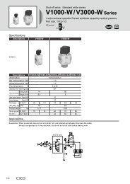
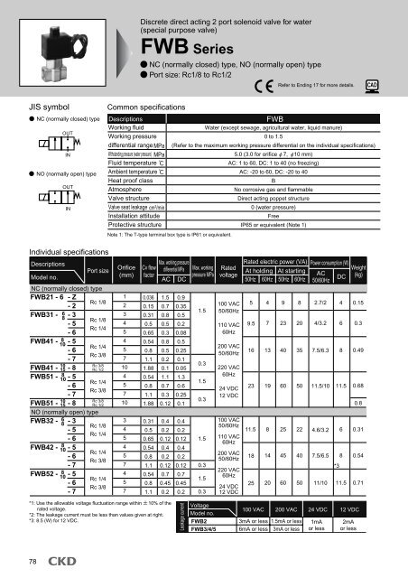
Discrete direct acting 2 port solenoid valve for water(special purpose valve)FWB SeriesNC (normally closed) type, NO (normally open) typePort size: Rc1/8 to Rc1/2Refer to Ending 17 for more details.JIS symbolNC (normally closed) typeOUTINNO (normally open) typeOUTINCommon specificationsDescriptionsWorking fluidWorking pressuredifferential range MPaWithstanding pressure (water pressure) MPaFluid temperatureAmbient temperatureHeat proof classAtmosphereValve structureValve seat leakage cm 3 /minInstallation attitudeProtective structureNote 1: The T-type terminal box type is IP61 or equivalent.FWBWater (except sewage, agricultural water, liquid manure)0 to 1.5(Refer to the maximum working pressure differential on the individual specifications)5.0 (3.0 for orifice 7, 10 mm)AC: 1 to 60, DC: 1 to 40 (no freezing)AC: -20 to 60, DC: -20 to 40BNo corrosive gas and flammableDirect acting poppet structure0 (water pressure)FreeIP65 or equivalent (Note 1)Individual specificationsDescriptionsPort sizeModel no.NC (normally closed) typeFWB21 - 6 - ZRc 1/8- 2FWB31 - 6 - 38 Rc 1/8- 5Rc 1/4- 6FWB41 - 810 - 5Rc 1/4- 6Rc 3/8- 710Rc 3/8FWB41 - 15 - 8 Rc 1/2FWB51 - 810 - 5Rc 1/4- 6Rc 3/8- 710Rc 3/8FWB51 - 15 - 8 Rc 1/2NO (normally open) typeFWB32 - 68 - 3Rc 1/8- 5Rc 1/4- 6FWB42 - 810 - 5Rc 1/4- 6Rc 3/8- 7FWB52 - 810 - 5Rc 1/4- 6Rc 3/8- 7Orifice(mm)123454571045710345457457Cv flowfactor0.0360.150.310.50.650.540.81.11.880.540.81.11.880.310.50.650.540.81.10.540.81.1Max. working pressureRated electric power (VA) Power consumption (W)differential MPa Max. working RatedAt holding At startingpressure MPa voltageACAC DC 50Hz 60Hz 50Hz 60HzDC50/60Hz1.50.70.80.50.30.80.50.20.11.10.70.30.120.40.20.120.40.20.120.70.450.2*1: Use the allowable voltage fluctuation range within 10% of therated voltage.*2: The leakage current must be less than values given at right.*3: 8.5 (W) for 12 VDC.0.90.350.50.20.080.50.250.10.051.30.60.250.10.40.20.120.40.20.120.70.450.2Leakage current1.50.31.50.31.50.31.50.3VoltageModel no.FWB2FWB3/4/5100 VAC50/60Hz110 VAC60Hz200 VAC50/60Hz220 VAC60Hz24 VDC12 VDC100 VAC50/60Hz110 VAC60Hz200 VAC50/60Hz220 VAC60Hz24 VDC12 VDC59.51611.518254 9 8 2.7/2100 VAC 200 VAC 24 VDC 12 VDC3mA or less 1.5mA or less6mA or less 3mA or less1mAor less4 0.157 23 20 4/3.2 6 0.313 40 35 7.5/6.3 8 0.4923 19 60 50 11.5/10 11.5 0.680.88 25 22 4.6/3.2 6 0.3114 45 40 7.5/6.5 8 0.54*320 60 50 11/10 11.5 0.712mAor lessWeight(kg)78
How to orderF W B 2 1 6 Z O 2C B 1No. of port(2 port valve)Working fluid(Water)A Size variationB ActuationFWB21-6-Z-02CB-1Model: FWBNote on model no. selectionC Port sizeD Orifice*1*2A Size variation : 22 mmB Actuation : NC (normally closed) typeC Port size : Rc 1/8D Orifice : 1E Body, sealant combination: Body - brass, sealant - NBRF Coil option : Grommet lead wireG Other options : Mounting plateH Voltage : 100 VAC 50/60Hz, 110 VAC 60HzE Body, sealant combination*3F Coil option*4G Otheroptions*1: Only bore sizes Rc1/4 (item (C) 8) and Rc3/8 (item (C) 10) are available forthe FWB41 and FWB51 orifice 4mm (item (D) 5), 5mm (item (D) 6), and7mm (item (D) 7).*2: The bore size Rc3/8 (item (C) 10) and Rc1/2 (item (C) 15) are available fororifice 10mm (item (D) 8).*3: The body is cast bronze for the orifice 10mm (item (D) 8) item (E) 0 (brass).*4: For item (F) 2CS, the surge suppressor is built into the body, and for 2HSand 3RS, built into the terminal box.*5: Consult with CKD for other voltages that cannot be manufactured.H Voltage*5FWB SeriesFWB*1 Series: NC (normally closed) typeSymbol DescriptionsA Size variation2 22 mm3 28 mm4 34 mm5 40 mmB Actuation12C681015DZ2356782CG2CH3T3RSNC (normally closed) typeNO (normally open) typeOptionG Other optionsBlank Standard NoneB Mounting plateH1234Port sizeOrificeRc 1 / 8Rc 1 / 4Rc 3 / 8Rc 1 / 2OptionVoltage12345710E Body, sealant combinationBody SealantO BrassNBRD Stainless steel NBRF Coil option2C Standard Grommet lead wire2CS2G2HSGrommet lead wire withsurge suppressorDIN terminal box (Pg11)DIN terminal box with lightand surge suppressor (Pg11)Conduit (CTC19)Conduit (G1/2)T type terminal box (G1/2)T type terminal box with lightand surge suppressor (G1/2)100 VAC 50/60Hz, 110 VAC 60Hz200 VAC 50/60Hz, 220 VAC 60Hz24 VDC12 VDCModel no.FWBFWBFWBFWBFWBFWB21 31 41 51 32 42For voltages other than the above, write in the voltage directly.Select from the combination of marks in the above table.FWB52HNB/GUSB/GFAB/GFGB/GFVBFWB/GFHBFLBABAGAP/ADAPK/ADKFordry airExplosionproofHVB/HVLSAB/SVBNP/NAP/NVPCHB/GMXB/GOther G.P.systemsPD/FAD/PJCVE/CVSECPE/CPDMedicalanalysisCustomorderSpecial purpose valve for waterDirect acting 2 port solenoid valve79
FWB SeriesFWB*1 Series: NC (normally closed) typeInternal structure and parts listFWB*1 series123456INOUTNo. Parts name Materials123456Coil assemblyCore assemblyPlunger assemblyO ringSpringBody-SUS, Cu (Ag when body is SUS)SUS, NBRNBRSUSC3771 or CAC407 (SUS)-Stainless steel, copper (silver when body is stainless steel)Stainless steel, nitrile rubberNitrile rubberStainless steelBrass or bronze (stainless steel)( ) shows option. Note: For the FWB4 and FWB5 orifice 10 and body seal material 0, the body is cast bronze.DimensionsGrommet lead wire typeFWB*1-*-*-*2C(Page 116)FGHEKLDINOUTCJABView AView AModel no.FWB21FWB31FWB41FWB41-10, 15-8FWB51FWB51-10, 15-8A323640504050B141821292129C81112151215D45.557.5677673.582.5E5668.581908998F15.518.522.526G19.522.52629.5H22283440JRc1/8Rc1/8, Rc1/4Rc1/4, Rc3/8Rc3/8, Rc1/2Rc1/4, Rc3/8Rc3/8, Rc1/2K15181818LM4 depth 6M5 depth 6M5 depth 8M5 depth 880
Optional dimensionsGrommet lead wire with surge suppressorFWB*1-*-*-* 2CSA(Page 116)BFWB SeriesFWB*1 Series: NC (normally closed) type(For common dimensions, refer to the grommet lead wire dimensions on the left page.)DIN terminal box (with light and surge suppressor)FWB*1-*-*-* 2G2HSAE (coil width)BHNB/GUSB/GFAB/GFGB/GCDFVBModel no.FWB21FWB31FWB41FWB51INA26.529.53437.5B22283440OUTModel no.FWB21FWB31FWB41FWB41-10, 15-8FWB51FWB51-10, 15-8INA B53 4458.5 476265.550.554FOUTC38393939D3951617069.578.5E22283440FPg9Pg11Pg11Pg11FWB/GFHBFLBABAGAP/ADT type terminal box (with light and surge suppressor) (G1/2)FWB*1-*-*-* 3T3RS(Coil width)AEB35INOUT36G1/2CDCKDConduit (CTC19, G1/2)FWB*1-*-*-* 2CS2CHINAOUTBC (coil width)DAPK/ADKFordry airExplosionproofHVB/HVLSAB/SVBNP/NAP/NVPCHB/GModel no.FWB31FWB41FWB41-10, 15-8FWB51FWB51-10, 15-8A929699.5Mounting plateFWB*1-*-*-*** BB60.564.568C5362.571.57180D7988.597.597106AE283440C 4-GModel no.FWB31FWB41FWB41-10, 15-8FWB51FWB41-10, 15-8A394346.5B5362.571.57180C283440DCTC19G1/2CTC19G1/2CTC19G1/2MXB/GOther G.P.systemsPD/FAD/PJCVE/CVSECPE/CPDMedicalanalysisCustomorderModel no.FWB21FWB31FWB41/51JKA B C D E F G H J K L40 3452 4256 4830 25 1540 30 1844 36 186-HELBDF15 5 4.5 6 1.2 2018 6 5.5 7 1.6 2518 6 5.5 7 1.6 30Special purpose valve for waterDirect acting 2 port solenoid valve81
FWB SeriesFWB*2 Series: NO (normally open) typeInternal structure and parts listFWB*2 series12345INOUT6No. Parts name1 Coil assembly2 Core assembly3 Valving element guide assembly4 O ring5 Spring6 Body( ) shows option.Materials-SUS, Cu (Ag when body is SUS)PPS, SUS, NBRNBRSUSC3771 (SUS)-Stainless steel, copper (silver when body is stainless steel)Polyphenylene sulfite, stainless steel, nitrile rubberNitrile rubberStainless steelBrass (stainless steel)DimensionsGrommet lead wire typeFWB*2-*-*-*2C(Page 116)FGHINOUTCDELKABJView AView ALead wire length 300mmModel no.FWB32FWB42FWB52A364040B182121C111212D62.571.578E8496103.5F18.522.526G22.52629.5H283440JRc1/8, Rc1/4Rc1/4, Rc3/8Rc1/4, Rc3/8K181818LM5 depth 6M5 depth 8M5 depth 882
Optional dimensionsGrommet lead wire with surge suppressorFWB*2-*-*-* 2CSA(Page 116)BFWB SeriesFWB*2 Series: NO (normally open) type(For common dimensions, refer to the grommet lead wire dimensions on the left page.)DIN terminal box (with light and surge suppressor)FWB*2-*-*-* 2G2HSABE (coil width)HNB/GUSB/GFAB/GFGB/GFVBFWB/GINOUTINOUTFCDFHBFLBModel no.FWB32FWB42FWB52A29.53437.5B283440Model no.FWB32FWB42FWB52A58.56265.5B4750.554C393939D56.56573.5E283440FPg11Pg11Pg11ABAGAP/ADT type terminal box (with light and surge suppressor) (G1/2)FWB*2-*-*-* 3T3RSBA(Coil width)E35Conduit (CTC19, G1/2)FWB*2-*-*-* 2CG2CHAC (coil width)DAPK/ADKFordry airExplosionproofHVB/HVLSAB/SVBNP/NAP/NVP36CDBCHB/GINOUTG1/2INOUTMXB/GModel no.FWB32FWB42FWB52A929699.5B60.564.568C586775D8493101E283440Model no.FWB32FWB42FWB52A394346.5B586775C283440DCTC19G1/2CTC19G1/2CTC19G1/2Other G.P.systemsPD/FAD/PJCVE/CVSEMounting plateFWB*2-*-*-** BAC4-GCPE/CPDMedicalanalysisCustomorderModel no.FWB32FWB42/52JKA B C D E F G H J K L52 4256 486-HEL40 30 18 1844 36 18 18BDF6 5.5 7 1.6 256 5.5 7 1.6 30Special purpose valve for waterDirect acting 2 port solenoid valve83
Direct acting 2 port solenoid valve for water, manifold(special purpose valve)GFWB SeriesNC (normally closed) typePort size: Rc1/8, Rc1/4, Rc3/8Refer to Ending 17 for more details.JIS symbolNC (normally closed) /common water supply type(Port C pressurized)Port CPort AOUTINPort AOUTINCommon specificationsDescriptionsWorking fluidWorking pressuredifferential range MPaWithstanding pressure (water pressure) MPaFluid temperatureAmbient temperatureHeat proof classAtmosphereValve structureValve seat leakage cm 3 /minInstallation attitudeProtective structureGFWBWater (except sewage, agricultural water, liquid manure)0 to 1.5(Refer to the maximum working pressure differential on the individual specifications)5.0 (3.0 for orifice 7 mm)AC: 1 to 60 DC: 1 to 40 (no freezing)AC: -20 to 40, DC: -20 to 40BNo corrosive gas and flammableDirect acting poppet structure0 (water pressure)FreeIP65 or equivalent (Note 1)Note 1: The T-type terminal box type is IP61 or equivalent.Individual specificationsDescriptions Port sizeMax. working pressureRated electric power (VA) Power consumption (W)Orifice Cv flowPort A Port Cdifferential MPa Max. working Rated(mm)At holding At startingpressure MPa voltageAC DCModel no.factor(Individual port) (Common port) AC DC 50Hz 60Hz 50Hz 60Hz 50/60HzNC (normally closed) typeGFWB21- ZRc1/8- 2GFWB31- 3- 5 Rc1/4- 6GFWB41- 5- 6 Rc1/4- 7GFWB51- 5- 6 Rc1/4- 7Rc1/4Rc3/8Rc3/8Rc3/81234545745700360.120.230.360.450.420.550.730.420.550.731.50.70.80.50.30.80.50.21.10.70.30.90.350.50.20.080.50.250.11.30.60.25*1: Use the allowable voltage fluctuation range within 10% of the rated voltage.*2: The leakage current must be less than values given below.*3: 8.6 (W) for 12 VDC.1.50.31.50.3100 VAC50/60Hz110 VAC60Hz200 VAC50/60Hz220 VAC60Hz24 VDC12 VDC59.516234 9 9 2.7/27 23 20 4/3.2 613 40 35 7.5/6.3 8*319 60 50 11.5/10 11.54Leakage currentVoltageModel no.GFWB2GFWB3/4/5100 VAC 200 VAC 24 VDC 12 VDC3mA or less 1.5mA or less6mA or less 3mA or less1mAor less2mAor less84
GFWB SeriesHow to orderManifoldG F W B 2 1 Z 3 0 2C 1Manifold with masking plateG F W B 3 1 5 X D 2G 2 5 2Model no.HNB/GUSB/GFAB/GNo. of port(2 port valve)Working fluid(Water)A Size variationB Circuit structureGFWB21-Z-3-02C-1Model: GFWBNote on model no. selectionC OrificeD Station no.*1*2E Body, sealant combinationF Coil option*3*4A Size variation : 22 mmB Circuit structure : NC (normally closed) / common water supply typeC Orifice : 1D Station no. : 3 stationsE Body, sealant combinationG Voltage: Body - brass, sealant - NBR*5F Coil option : Grommet lead wireG Voltage : 100 VAC 50/60Hz, 110 VAC 60HzH I: No masking plate*1: For the number of manifold stations, select a number of stations from 2 to 10.*2: For the type with masking plate, designate the item (D) as "X", then designatethe number of (H) solenoid valves and (I) masking plates.*3: For GFWB21 item (F) 2G and 2HS, the compact terminal box (Pg9) is used.*4: For item (F) 2CS, the surge suppressor is built into the coil, and for 2HS and3RS, it is built into the terminal box.*5: Consult with CKD for other voltages that cannot be manufactured.*6: Solenoid valves are arranged from the right side facing the sub-plate A(independent) port.*7: Orders for only the masking plate and sub-plate are also available. ContactCKD for details.H Solenoidvalve quantity*6I MaskingSymbol DescriptionsA Size variation2 22 mm3 28 mm4 34 mm5 40 mmB Circuit structure1C OrificeZ23567F Coil option2C Standard2CS2G2HS2CG2CH3T3RS1234NC (normally closed) / common water supply typeD Station no.2 2 stationsto to10 10 stationsO Actuator onlyX With masking plateE Body, sealant combinationBody SealantO BrassNBRD Stainless steel NBROption123457G VoltageGrommet lead wireGrommet lead wire withsurge suppressorDIN terminal box (Pg11)DIN terminal box with lightand surge suppressor (Pg11)Conduit (CTC19)Conduit (G1/2)T type terminal box (G1/2)T type terminal box with lightand surge suppressor (G1/2)100 VAC 50/60Hz, 110 VAC 60Hz200 VAC 50/60Hz, 220 VAC 60Hz24 VDC12 VDCGFWB21GFWB31G GF FWBWB41 51For voltages other than the above, write in the voltage directly.H Solenoid valve quantityBlank No masking plate1 One solenoid valveto to9 Nine solenoid valvesI Masking plate quantityBlank No masking plate1 One masking plateto to9 Nine masking platesSelect from the combination of marks in the above table.85FGB/GFVBFWB/GFHBFLBABAGAP/ADAPK/ADKFordry airExplosionproofHVB/HVLSAB/SVBNP/NAP/NVPCHB/GMXB/GOther G.P.systemsPD/FAD/PJCVE/CVSECPE/CPDMedicalanalysisCustomorderSpecial purpose valve for waterDirect acting 2 port solenoid valve
GFWB SeriesInternal structure and parts listGFWB actuator123456OUTIN78GFWB manifold123456789101112No.123456Parts name MaterialsCoil assembly -Core assembly SUS, Cu-Stainless steel, copper(Ag when body is SUS) (Silver when body is stainless steel)Plunger assembly SUS, NBRStainless steel, nitrile rubberO ringSpringBodyNBRSUSC3771 (SUS)Nitrile rubberStainless steelBrass (stainless steel)No. Parts name Materials789O ringO ringConnectorNBRNBRC3604Nitrile rubberNitrile rubberBrass(SUS when body is SUS) (Stainless steel when body is stainless steel)1011O ringSub-plateNBRC3604Nitrile rubberBrass(SUS when body is SUS) (Stainless steel when body is stainless steel)12 Connecting plate SPCSteel( ) shows option.86
GFWB SeriesDimensions: ManifoldGrommet lead wire typeGFWB*1-*-*-*2C(Page 116)HNB/GUSB/GFAB/GGHFGB/GFVBVMasking plateFWB/GFHBEFFLBABD2-C(Port C)LUJKAABBMLN PABAGAP/ADAPK/ADKFordry airQRSExplosionproofHVB/HVLSAB/SVBNP/NAP/NVPCHB/GModel no. 2 3 4 5 6 7 8 9 10SymbolGFWB2GFWB3GFWB4GFWB5AABBAABBAABBAABB8193971091061191181311091211331451451581631761621741942062122252362491651772052172232362532662182302662782903033263392462583023143293423713842742863383503683814164293273393994114354484895023303424104224464595065195 stations 5 stationsManifold structure 2 stations x 1 3 stations x 1 2 stations x 2 5 stations x 1 3 stations x 2 + 2 stations + 3 stations 3 stations x 3 5 stations x 2Model no.GFWB2GFWB3GFWB4GFWB5Stn. no.Note: The manifold structure is a connected type based on 2, 3 or 5 stations.n-T(Port A)A B C D E F G H J K L M N P3238424213.514.516.516.5Rc1/4Rc3/8Rc3/8Rc3/817.518.519.519.566.575.584907786.59810515.518.522.52619.522.52629.52630333628363945666.56.51.62226.56.57.57.521242424* Lead wire length 300mmQ R S T U V222830304.54.55.55.52.52.52.52.5Rc1/8Rc1/4Rc1/4Rc1/417.319191944.64.64.6MXB/GOther G.P.systemsPD/FAD/PJCVE/CVSECPE/CPDMedicalanalysisCustomorderSpecial purpose valve for waterDirect acting 2 port solenoid valve87
GFWB SeriesDimensions: ActuatorGrommet lead wire typeGFWB*1-*-O-*2CFGHM4-LENCKDABView AJView ALead wire length 300mmModel no.GFWB2GFWB3GFWB4GFWB5A B C D E F G H J K L323842422734384444.54.55.5394552.558.549.55666.573.515.518.522.52619.522.52629.52228344019252834242932323.54.54.54.5Applicable O ringM NAS568-009AS568-011AS568-012AS568-012AS568-018AS568-022AS568-025AS568-025Actuator installation dimension drawingIN sideGAG2 x 2n-FDEOUT sideBBn-4 cutDepth 3.5 and over,IN side not penetrated2-n-CMachining drawing, when 2 actuators are used.Model no.GFWB2GFWB3GFWB4GFWB5A28 and over35 and over39 and over45 and overB19 0.125 0.128 0.134 0.1C D E F G3.5 cut or less5.5 cut or less10.613.80.10.124290.10.1M3 effective thread depth 6 and overM4 effective thread depth 6 and over660.20.27.5 cut or less7.5 cut or less17170.10.132320.10.1M4 effective thread depth 6 and overM4 effective thread depth 6 and over770.20.288
GFWB SeriesOptional dimensionsGrommet lead with surge suppressorGFWB*1-*-*-* 2CS(Page 116)(For common dimensions, refer to the grommet lead wire actuator dimensions on the left page.)DIN terminal box (with light and surge suppressor)GFWB*1-*-*-* 2G2HSHNB/GUSB/GFAB/GABBAE (coil width)FGB/GFVBFWB/GFHBFLBDCABAGModel no.GFWB2GFWB3GFWB4GFWB5A26.529.53437.5B22283440Conduit (CTC19, G1/2)GFWB*1-*-*-* 2CG2CHModel no.GFWB2GFWB3GFWB4GFWB5A5358.56265.5FB C D E F444750.5543839393932.538.546.55422283440Pg9Pg11Pg11Pg11T type terminal box (with light and surge suppressor) (G1/2)GFWB*1-*-*-* 3T3RSAP/ADAPK/ADKFordry airExplosionproofHVB/HVLSAB/SVBNP/NAP/NVPCHB/GMXB/GAC (coil width)BA(Coil width)E35Other G.P.systemsPD/FAD/PJCVE/CVSEDCPE/CPDB36DCCKDMedicalanalysisCustomorderModel no.GFWB3GFWB4GFWB5A394346.5B40.54855.5C283440DCTC19 G1/2CTC19 G1/2CTC19 G1/2Model no.GFWB3GFWB4GFWB5A929699.5B60.564.568C40.54855.5D66.57481.5G1/2E283440Special purpose valve for waterDirect acting 2 port solenoid valve89
Discrete direct acting 3 port solenoid valve for water(special purpose valve)FWG SeriesUniversal typePort size: Rc1/8, Rc1/4, Rc3/8Refer to Ending 17 for more details.JIS symbolUniversal typeCOMNO NCCommon specificationsDescriptionsWorking fluidWorking pressuredifferential range MPaMax. working pressure MPaWithstanding pressure (water pressure) MPaFluid temperatureAmbient temperatureHeat proof classAtmosphereValve structureValve seat leakage cm 3 /minInstallation attitudeProtective structureNote 1: The T-type terminal box type is IP61 or equivalent.FWGWater (except sewage, agricultural water, liquid manure)0 to 1.0(Refer to the maximum working pressure differential on the individual specifications)1.02.0AC: 1 to 60, DC: 1 to 40 (no freezing)AC: -20 to 60, DC: -20 to 40BNo corrosive gas and flammableDirect acting poppet structure0 (water pressure)FreeIP65 or equivalent (Note 1)Individual specificationsDescriptionsPort sizeModel no.Universal typeFWG21- 6 - Z Rc 1/86FWG31- 8 -0 Rc 1/8, Rc 1/48FWG41- 10 -1 Rc 1/4, Rc 3/8FWG51- 8-4 Rc 1/4, Rc 3/810Orifice(mm)11.523Cv flowfactor0.0360.0800.140.31Max. working pressureRated electric power (VA) Power consumption (W)differential MPa Rated voltage At holding At starting AC DCAC DC 50Hz 60Hz 50Hz 60Hz 50/60Hz0.70.710.6 *20.70.710.6 *2*1: Use the allowable voltage fluctuation range within 10% of the rated voltage.*2: 0.4 only when NO pressurized*3: The leakage current must be less than values given below.*4: 8.6 (W) for 12 VDC.100 VAC 50/60Hz110 VAC 60Hz200 VAC 50/60Hz220 VAC 60Hz24 VDC12 VDC6.5162232510.516221023406092035503.6/2.57/4.18.5/6.512.5/10.5468*411.5Weight(kg)0.170.330.520.69Leakage currentVoltageModel no.FWG2FWG3/4/5100 VAC 200 VAC 24 VDC 12 VDC3mA or less 1.5mA or less6mA or less 3mA or less1mAor less2mAor less90
FWG SeriesHow to orderF W G 2 1 6 Z O 2C B 1No. of port(3 port valve)Working fluid(Water)A Size variationB ActuationC Port sizeFWG21-6-Z-02CB-1Model: FWGNote on model no. selectionD OrificeA Size variation : 22 mmB Actuation : Universal typeC Port size : Rc1/8D Orifice : 1E Body, sealant combination: Body - brass, sealant - NBRF Coil option : Grommet lead wireG Other options : Mounting plateH Voltage : 100 VAC 50/60Hz, 110 VAC 60HzE Body, sealant combinationF Coil option*1*2*1: For FWG21 item (F) 2G and 2HS, the compact terminal box (Pg9) is used.*2: For item (F) 2CS, the surge suppressor is built into the coil, and for 2HSand 3RS, it is built into the terminal box.*3: Consult with CKD for other voltages that cannot be manufactured.G Other optionsH Voltage*3Symbol DescriptionsA Size variation234522 mm28 mm34 mm40 mmB Actuation1 Universal typeC Port size6810DZO14EODRc1/8Rc1/4Rc3/8F Coil option2C Standard2CS2G2HS2CG2CH3T3RSOptionG Other optionsBlank NoneB Mounting plateH Voltage1234Orifice11.523Body, sealant combinationBodyBrassStainless steelGrommet lead wireGrommet lead wire withsurge suppressorDIN terminal box (Pg11)DIN terminal box with lightand surge suppressor (Pg11)Conduit (CTC19)Conduit (G1/2)T type terminal box (G1/2)T type terminal box with lightand surge suppressor (G1/2)100 VAC 50/60Hz, 110 VAC 60Hz200 VAC 50/60Hz, 220 VAC 60Hz24 VDC12 VDCFor voltages other than the above, write in the voltage directly.Select from the combination ofSealantNBRNBRModel no.F F F FW W W WGG G G21 31 41 51marks in the above table.91HNB/GUSB/GFAB/GFGB/GFVBFWB/GFHBFLBABAGAP/ADAPK/ADKFordry airExplosionproofHVB/HVLSAB/SVBNP/NAP/NVPCHB/GMXB/GOther G.P.systemsPD/FAD/PJCVE/CVSECPE/CPDMedicalanalysisCustomorderSpecial purpose valve for waterDirect acting 3 port solenoid valve
FWG SeriesInternal structure and parts listFWG*1 SeriesNO1234COMNC567No.1234567Parts nameSocketCoil assemblyCore assemblyPlunger assemblyO ringSpringBodyDimensionsGrommet lead wire typeFWG*1-*-*-*2CMaterialsC3604 (SUS when body is SUS)-SUS, Cu (Ag when body is SUS)SUS, NBRNBRSUSC3771 (SUS)(Page 116)FNOGBrass (Stainless steel when body is stainless steel)-Stainless steel, copper (silver when body is stainless steel)Stainless steel, nitrile rubberNitrile rubberStainless steelBrass (stainless steel)( ) shows option.HKDECOMCNCJAMBLLead wire length 300mmModel no. A B CFWG21FWG31FWG41FWG5132364040141821218111212* (E) are dimensions for stainless steel.D E (E) F G H J K L M45.5 74 75(Rc1/8: 90)15.557.56773.590103111(Rc1/4: 91.5)10511318.522.52619.522.52629.522283440Rc1/8Rc1/8, Rc1/4Rc1/4Rc3/8Rc1/4Rc3/814171722172215181818M4 depth 6M5 depth 6M5 depth 8M5 depth 892
FWG SeriesOptional dimensionsGrommet lead wire with surge suppressorFWG*1-*-*-* 2CS(Page 116)(For common dimensions, refer to the grommet lead wire dimensions on the left page.)DIN terminal box (with light and surge suppressor)FWG*1-*-*-* 2G2HSHNB/GUSB/GNOABNOAB(Coil width)EFAB/GFGB/GFVBFWB/GCOMNCCOMNCCFDFHBModel no.FWG21FWG31FWG41FWG51A26.529.53437.5B22283440Model no.FWG21FWG31FWG41FWG51A5358.56265.5B C D E F444750.5543839393939516169.522283440Pg9Pg11Pg11Pg11FLBABAGAP/ADConduit (CTC19, G1/2)FWG*1-*-*-* 2CG2CHT type terminal box (with light and surge suppressor) (G1/2)FWG*1-*-*-* 3T3RSAPK/ADKFordry airANO(Coil width)CDBNOAD(Coil width)E35ExplosionproofHVB/HVLSAB/SVBNP/NAP/NVPCOMNCBCOMNC36CG1/2CHB/GMXB/GModel no.FWG31FWG41FWG51A394346.5B5362.571C283440DCTC19, G1/2CTC19, G1/2CTC19, G1/2Model no.FWG31FWG41FWG51A929699.5B60.564.568C5362.571D7988.597E283440Other G.P.systemsPD/FAD/PJCVE/CVSEMounting plateFWG*1-*-*-** BAC 4-GCPE/CPDMedicalanalysisCustomorderModel no.FWG21FWG31FWG41/51BDFJKA B C D E F G H J K L40 34 30 25 1552 42 40 30 1856 48 44 36 186-HEL15 518 618 64.55.55.56771.2 201.6 251.6 30Special purpose valve for waterDirect acting 3 port solenoid valve93
GFWG SeriesDirect acting 3 port solenoid valve for water, manifold(special purpose valve)GFWG SeriesUniversal typePort size: Rc1/8, Rc1/4, Rc3/8Refer to Ending 17 for more details.JIS symbolCommon water supply /individual drain typePort APort CPort ACOMNCNOCOMNCNOCommon specificationsDescriptionsWorking fluidWorking pressuredifferential rangeMPaMax. working pressure MPaWithstanding pressure (water pressure) MPaFluid temperatureAmbient temperatureHeat proof classAtmosphereValve structureValve seat leakage cm 3 /minInstallation attitudeProtective structureGFWGWater (except sewage, agricultural water, liquid manure)0 to 1.0(Refer to the maximum working pressure differential on the individual specifications)1.02.0AC: 1 to 60, DC: 1 to 40 (no freezing)AC: -20 to 40, DC: -20 to 40BNo corrosive gas and flammableDirect acting poppet structure0 (water pressure)FreeIP65 or equivalent (Note 1)Note 1: The T-type terminal box type is IP61 or equivalent.Individual specificationsPort sizeMax. workingDescriptionsRated electric power (VA) Power consumption (W)Orifice Cv flow pressure differentialPort A/NO Port CRated voltage(mm)MPaAt holding At starting AC DCModel no.factor(Individual port) (Common port) AC DC 50Hz 60Hz 50Hz 60Hz 50/60HzUniversal typeGFWG21- ZGFWG31- 0GFWG41- 1GFWG51- 4Rc1/8Rc1/4Rc1/4Rc1/4Rc1/4Rc3/8Rc3/8Rc3/811.5230.0360.0800.140.270.7 0.70.7 0.71.0 1.00.6 *2 0.6 *2*1: Use the allowable voltage fluctuation range within 10% of the rated voltage.*2: 0.4 only when NO pressurized*3: The leakage current must be less than values given below.*4: 8.6 (W) for 12 VDC.100 VAC 50/60Hz110 VAC 60Hz200 VAC 50/60Hz220 VAC 60Hz24 VDC12 VDC6.51622325 10 9 3.6/2.5 410.5 23 20 7/4.1 616 40 35 8.5/6.5 8 *422 60 50 12.5/10.5 11.5Leakage currentVoltageModel no.GFWG2GFWG3/4/5100 VAC 200 VAC 24 VDC 12 VDC3mA or less 1.5mA or less1mA or less6mA or less 3mA or less2mA or less94
GFWG SeriesHow to orderManifoldG F W G 2 1 Z 5 0 2C 1Manifold with masking plateG F W G 3 1 4 X D 2G 2 3 6HNB/GUSB/GFAB/GNo. of port(3 port valve)Working fluid(Water)A Size variationB Circuit structureGFWG21-Z-5-02C-1Model: GFWGC OrificeD Station no.*1*2E Body, sealant combinationF Coil option*3*4A Size variation : 22 mmB Circuit structure: Common water supply / individual drain typeC Orifice : 1G VoltageD Station no. : 5 stations*5E Body, sealant combination: Body - brass, sealant - NBRF Coil option : Grommet lead wireG Voltage : 100 VAC 50/60Hz, 110 VAC 60HzH I: No masking plateNote on model no. selectionH Solenoidvalve quantity*6SymbolDescriptionsA Size variation2 22 mm3 28 mm4 34 mm5 40 mmB Circuit structure1 Common water supply / individual drain typeC OrificeD Station no.2 2 stationsto to10 10 stationsO Actuator onlyX With masking plateF Coil option2C Standard2CS2G2HS*1: For the number of manifold stations, select a number of stations from 2 to 10.*2: For the type with masking plate, designate the item (D) as "X", then designate the9 Nine solenoid valvesnumber of (H) solenoid valves and (I) masking plates.I Masking plate quantity*3: For GFWG21 item (F) 2G and 2HS, the compact terminal box (Pg9) is used. I Masking*4: For item (F) 2CS, the surge suppressor is built into the coil, and for 2HS and 3RS,Blank No masking plateplate quantityit is built into the terminal box.1 One masking plate*5: Consult with CKD for other voltages that cannot be manufactured.to to*6: Solenoid valves are arranged from the right side facing the sub-plate A (independent) port.*7: Orders for only the masking plate and sub-plate are also available. Contact CKD for details.9 Nine masking platesSelect from the combination of marks in the above table.EZO14Body, sealant combinationBodyBrassStainless steelOD2CG2CH3T3RSOption11.523Grommet lead wireGrommet lead wire withsurge suppressorDIN terminal box (Pg11)DIN terminal box with lightand surge suppressor (Pg11)Conduit (CTC19)Conduit (G1/2)T type terminal box (G1/2)T type terminal box with lightand surge suppressor (G1/2)H Solenoid valve quantityBlank No masking plate1 One solenoid valveto toSealantNBRNBRModel no.G G G GF F F FW W W WG G G G21 31 41 51G Voltage1 100 VAC 50/60Hz, 110 VAC 60Hz2 200 VAC 50/60Hz, 220 VAC 60Hz3 24 VDC4 12 VDCFor voltages other than the above, write in the voltage directly.95FGB/GFVBFWB/GFHBFLBABAGAP/ADAPK/ADKFordry airExplosionproofHVB/HVLSAB/SVBNP/NAP/NVPCHB/GMXB/GOther G.P.systemsPD/FAD/PJCVE/CVSECPE/CPDMedicalanalysisCustomorderSpecial purpose valve for waterDirect acting 3 port solenoid valve
GFWG SeriesInternal structure and parts listGFWG actuator1NO2345679COMNC8GFWG manifold12345678912101113No. Parts name MaterialsNo. Parts name1 Socket C3604Brass (Stainless steel when 8 O ring(SUS when body is SUS) body is stainless steel) 9 O ring2 Coil assembly --10 Connector3 Core assembly SUS, CuStainless steel, copper4(Ag when body is SUS)Plunger assembly SUS, NBR(Silver when body is stainless steel) 11Stainless steel, nitrile rubber 12O ringSub-plate567O ringSpringBodyNBRSUSC3771 (SUS)Nitrile rubberStainless steelBrass (stainless steel)13 Connecting plateMaterialsNBRNBRC3604(SUS when body is SUS)NBRC3604(SUS when body is SUS)SPCNitrile rubberNitrile rubberBrass (Stainless steel whenbody is stainless steel)Nitrile rubberBrass (Stainless steel whenbody is stainless steel)Steel( ) shows option.96
GFWG SeriesDimensions: ManifoldGrommet lead wire typeGFWG*1-*-*-*2C(Page 116)HNB/GUSB/GFAB/GGHUV (Port NO)FGB/GFVBFWB/GFHBEFXMasking plateFLBABADB 2-C(Port C)RWLSJKAABBMN PLAGAP/ADAPK/ADKFordry airExplosionproofHVB/HVLQn-T (Port A)Lead wire length 300mmSAB/SVBNP/NAP/NVPCHB/GMXB/GStn. no.Model no. 2 3 4 5 6 7 8 9 10SymbolGFWG2GFWG3GFWG4GFWG5AAAAAAAA8197106118109133145163162194212236165205223253218266290326246302329371274338368416327399435489330410446506BBBBBBBB931091191311211451581761742062252491772172362662302783033392583143423842863503814293394114485023424224595195 stations 5 stationsManifold structure 2 stations x 1 3 stations x 1 2 stations x 2 5 stations x 1 3 stations x 2 + 2 stations + 3 stations 3 stations x 3 5 stations x 2Note: The manifold structure is a connected type based on 2, 3 or 5 stations.Model no. A B C D E F (F) G H J K L M N PGFWG2GFWG3GFWG4GFWG53238424213.514.516.516.5Rc1/4Rc3/8Rc3/8Rc3/817.518.519.519.566.575.5849095108120127(96)(109)(121.5)(128.5)15.518.522.52619.522.52629.52630333628363945666.56.51.62226.56.57.57.521242424* (F) are dimensions for stainless steel.Q R S T U V W X222830304.54.55.55.52.52.52.52.5Rc1/8Rc1/4Rc1/4Rc1/414171717Rc1/8Rc1/4Rc1/4Rc1/417.3 419 4.619 4.619 4.6Other G.P.systemsPD/FAD/PJCVE/CVSECPE/CPDMedicalanalysisCustomorderSpecial purpose valve for waterDirect acting 3 port solenoid valve97
GFWG SeriesDimensions: Actuator(Page 116)Grommet lead wire typeGFWG*1-*-O-*2CFGHJOpposite sideof hexagonM4-MQPELCADKView ABView ALead wire length 300mmModel no.A B C D E (E) F G H J K L MGFWG2GFWG3GFWG4GFWG5323842422734384444.54.55.5* (E) are dimensions for stainless steel.394552.558.567.577.588.595.5(68.5)(78.5)(90)(97)15.518.522.52619.522.52629.5222834401417171719252834242932323.54.54.54.5NRc1/8Rc1/4Rc1/4Rc1/4Applicable O ringPQAS568-009 AS568-018AS568-011 AS568-022AS568-012 AS568-025AS568-012 AS568-025Actuator installation dimension drawingPort C sideGAG2 x 2n-FDEn-4 cutPort A sideBBDepth 3.5 and over, Port Aside not penetrated.2-n-CMachining drawing, when 2 actuators are used.Model no.GFWG2GFWG3GFWG4GFWG5A28 and over35 and over39 and over45 and overB19 0.125 0.128 0.134 0.1C D E F G3.5 cut or less5.5 cut or less10.613.80.10.17.5 cut or less7.5 cut or less17170.10.1242932320.10.10.10.1M3 effective thread depth 6 and overM4 effective thread depth 6 and overM4 effective thread depth 6 and overM4 effective thread depth 6 and over66770.20.20.20.298
GFWG SeriesOptional dimensionsGrommet lead with surge suppressorGFWG*1-*-*-* 2CS(Page 116)(For common dimensions, refer to the grommet lead wire actuator dimensions on the left page.)DIN terminal box (with light and surge suppressor)GFWG*1-*-*-* 2G2HSHNB/GUSB/GAFAB/GABBE (coil width)FGB/GFVBFWB/GFHBDCFLBModel no.GFWG2GFWG3GFWG4GFWG5A26.529.53437.5B22283440Conduit (CTC19, G1/2)GFWG*1-*-*-* 2CG2CHModel no.GFWG2GFWG3GFWG4GFWG5A5358.56265.5FB C D E F444750.5543839393932.538.546.55422283440Pg9Pg11Pg11Pg11T type terminal box (with light and surge suppressor) (G1/2)GFWG*1-*-*-* 3T3RSABAGAP/ADAPK/ADKFordry airExplosionproofHVB/HVLSAB/SVBNP/NAP/NVPCHB/GABC (coil width)DBA36CDE (coil width)35MXB/GOther G.P.systemsPD/FAD/PJCVE/CVSECPE/CPDG1/2MedicalanalysisCustomorderModel no.GFWG3GFWG4GFWG5A394346.5B40.54855.5C283440DCTC19, G1/2CTC19, G1/2CTC19, G1/2Model no.GFWG3GFWG4GFWG5A929699.5B60.564.568C40.54855.5D66.57481.5E283440Special purpose valve for waterDirect acting 3 port solenoid valve99