SRL3 Rodless cylinder - CKD
SRL3 Rodless cylinder - CKD
SRL3 Rodless cylinder - CKD
- No tags were found...

You also want an ePaper? Increase the reach of your titles
YUMPU automatically turns print PDFs into web optimized ePapers that Google loves.
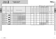
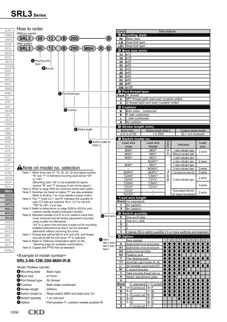
<strong>SRL3</strong> SeriesSCP*2CMK2CMA2SCMSCGSCA2SCSCKV2CA/OV2SSDCATMDC2MVCSMD2MSD*FC*STKULK*JSK/M2JSGJSC3USSDUSCJSB3LMBSTGSTS LLCSLCGLCMLCTLCYSTR2UCA2HCMHCA<strong>SRL3</strong>SRG3SRM3SRT3MRL2MRG2SM-25CAC4UCAC2RCC2MFCSHCGLCEnding2006How to orderWithout switch<strong>SRL3</strong> 00 12 B 200 BWith switch<strong>SRL3</strong>0012A Mounting styleNote 1B Bore sizeC Port thread typeD Cushion<strong>SRL3</strong>-00-12B-200-M0H-R-B200 M0HE Stroke lengthRBF Switch model no.Note 3Model: <strong>Rodless</strong> <strong>cylinder</strong>A Mounting style : Basic typeB Bore size : ø12mmC Port thread type : Rc threadD Cushion : Both sides cushionedE Stroke length : 200mmF Switch model no. : Reed switch M0H and lead wire 1mG Switch quantity : 1 on rod endH Option: Port position F, cushion needle position BBNote on model no. selectionNote 1: When bore size 12, 16, 20, 25, 32 and option symbol"R" and "T" is selected,mounting style will be "00"or "LB1".(Mounting style "LB" is not available for optionsymbol "R" and "T" because it can not be piped )Note 2: Refer to page 2004 for minimum stroke with switch.Note 3: Switches not listed on option "F" are also available.Refer to Ending 1 for more details (custom order)Note 4: The "*" mark on L* and N* indicates the quantity ofsets. If 2 sets are required, fill in "L2" for LB and"N2" for LB1. 2 pcs./setNote 5: Refer to dimensions on page 2026 to 2031for port,cushion needle position indication symbol.Note 6: Standard models of ø12 to ø15 needs to have theircover removed and full stroke adjustment mountedusing a plate nut afterwards."A3" is a option that will have a plate nut for mountinginstalled beforehand so that it can be mountedafterwards without removing the cover.Note 7: Thread size will be M4 for ø12 and ø16, and threadsize will be M5 for ø20 when "H" is selected.Note 8: Refer to "Optional combination table" on thefollowing page for available combinations.Note 9: Copper and PTFE free as standard.G Switch quantityH OptionNote 4, Note 5Note 6, Note 7Note 8SymbolA Mounting style00 Basic typeLB Axial foot typeLB1 Axial foot typeB Bore size (mm)121620253240506380100CBlankNGø12ø16ø20ø25ø32ø40ø50ø63ø80ø100*Lead wire lengthBlank 1m (standard)3 3m (option)5 5m (option)G Switch quantityR One on R sideL One on L sideD 2T 34 4 pieces (fill in switch quantity if 4 or more switches are required.)H Option Bore size (ø)Bore size(ø)Adjustable full-stroke R end only, with shock absorberAdjustable full-stroke L end only, with shock absorberAdjustable full-stroke bracket retrofittingFloating jointThin floating jointIntermediate support bracket (00, LB)With intermediate support bracket (LB1)C mount bracketTable mounting thread size upHeight adjustment plateF (standard)R (common port)FR (common port)DDF (common port)F (standard)FBBFDFDescriptionsD CushionBRLNBoth sides cushionedR side cushionedL side cushionedNo cushionE Stroke length (mm)Bore size Stroke length Note 2 Custom stroke lengthø12 to ø1001 to 5000 By 1 mm incrementF Switch model no.Lead wire Lead wireLeadIndicatorAxialRadialwireAA1A2A3YY1L*N*CHUBlankRBTDSXPort thread typeRc threadNPT thread (ø20 and over) (custom order)G thread (ø20 and over) (custom order)M0H*M5H*M2H*–M3H*–M3PH*T2WH*T2YH*T3WH*T3YH*T2YD*T2YDT*Port positionM0V*M5V*M2V*M2WV*M3V*M3WV*M3PV*T2WV*T2YV*T3WV*T3YV*––Cushion needle positionContact Reed Proximity1 color indicator typeWithout indicator light1 color indicator type2 color indicator type1 color indicator type2 color indicator type1 color indicator type (custom order)2 color indicator typeStrong magnetic field proof(AC magnetic field dedicated)2-wire2-wire3-wire3-wire2-wire3-wire2-wire12 16 20 25 32 40 50 63 80 100