Valve and Valve Actuator Selection Guide - Staefa Control System
Valve and Valve Actuator Selection Guide - Staefa Control System
Valve and Valve Actuator Selection Guide - Staefa Control System

Create successful ePaper yourself
Turn your PDF publications into a flip-book with our unique Google optimized e-Paper software.
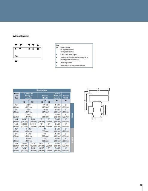
SQS65SQS65.5Wiring DiagramKeyG0YRMU<strong>System</strong> NeutralG <strong>System</strong> PotentialG0 <strong>System</strong> Potential0 to 10 Vdc <strong>Control</strong> SignalInput for 0 to 100 Ohm remote setting unit orlow temperature detection unitMeasuring neutralOutput for 0 to 10 Vdc postion indicationDimensions<strong>Valve</strong> Center Line ActualLine to Top of Service Width of ServiceSize <strong>Actuator</strong> Height <strong>Actuator</strong> WidthH 1 H W 1 WNO NC NO NC1/2” 6-5/8” 14-1/2” 5-1/16” 9”(15 mm) (167 mm) (370 mm) (128 mm) (225 mm)3/4” 6-5/8” 14-1/2” 5-1/16” 9”(20 mm) (167 mm) (370 mm) (128 mm) (225 mm)1” 6-7/8” 15” 5-1/16” 9”(25 mm) (173 mm) (380 mm) (128 mm) (225 mm)1-1/4” 8-1/4” 7-3/4” 16” 9” 5-1/16” 13”(32 mm) (210 mm) (195 mm) (406 mm) (225 mm) (128 mm) (225 mm)1-1/2” 8-15/16” 7-11/16” 16” 9” 5-1/16” 13”(40 mm) (211 mm) (195 mm) (406 mm) (225 mm) (128 mm) (225 mm)1/2” 6-1/16” 14” 5-1/16” 9”(15 mm) (153 mm) (355 mm) (128 mm) (225 mm)3/4” 6-1/16” 14” 5-1/16” 9”(20 mm) (153 mm) (355 mm) (128 mm) (225 mm)1” 6-5/16” 14-1/2” 5-1/16” 9”(25 mm) (159 mm) (370 mm) (128 mm) (225 mm)1-1/4” 7-11/16” 7-3/16” 15-1/2” 9” 5-1/16” 13”(32 mm) (195 mm) (183 mm) (394 mm) (225 mm) (128 mm) (225 mm)1-1/2” 7-3/4” 7-1/8” 15-1/2” 9” 5-1/16” 13”(40 mm) (197 mm) (181 mm) (406 mm) (225 mm) (128 mm) (225 mm)43