Valve and Valve Actuator Selection Guide - Staefa Control System
Valve and Valve Actuator Selection Guide - Staefa Control System
Valve and Valve Actuator Selection Guide - Staefa Control System

You also want an ePaper? Increase the reach of your titles
YUMPU automatically turns print PDFs into web optimized ePapers that Google loves.
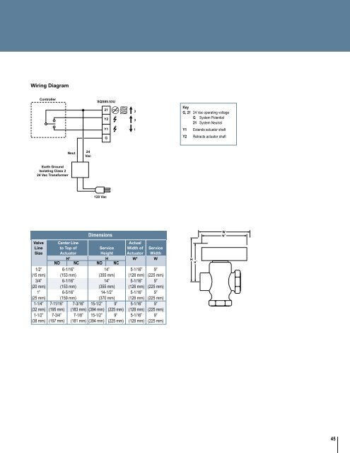
Wiring Diagram<strong>Control</strong>lerSQS85.53U21Y200KeyG, 21 24 Vac operating voltageG <strong>System</strong> Potential21 <strong>System</strong> NeutralY11Y1Extends actuator shaftGY2Retracts actuator shaftNeut 24VacEarth GroundIsolating Class 224 Vac Transformer120 VacDimensions<strong>Valve</strong> Center Line ActualLine to Top of Service Width of ServiceSize <strong>Actuator</strong> Height <strong>Actuator</strong> WidthH 1 H W 1 WNO NC NO NC1/2” 6-1/16” 14” 5-1/16” 9”(15 mm) (153 mm) (355 mm) (128 mm) (225 mm)3/4” 6-1/16” 14” 5-1/16” 9”(20 mm) (153 mm) (355 mm) (128 mm) (225 mm)1” 6-5/16” 14-1/2” 5-1/16” 9”(25 mm) (159 mm) (370 mm) (128 mm) (225 mm)1-1/4” 7-11/16” 7-3/16” 15-1/2” 9” 5-1/16” 9”(32 mm) (195 mm) (183 mm) (394 mm) (225 mm) (128 mm) (225 mm)1-1/2” 7-3/4” 7-1/8” 15-1/2” 9” 5-1/16” 9”(38 mm) (197 mm) (181 mm) (394 mm) (225 mm) (128 mm) (225 mm)45