Frequency inverter M-Max - Moeller
Frequency inverter M-Max - Moeller
Frequency inverter M-Max - Moeller
- No tags were found...

You also want an ePaper? Increase the reach of your titles
YUMPU automatically turns print PDFs into web optimized ePapers that Google loves.
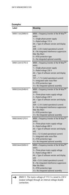
Engineering04/10 MN04020001Z-ENMotor and ApplicationMotor selectionGeneral recommendations for motor selection:• Use three-phase powered asynchronous motors with shortcircuitrotors and surface cooling, also called asynchronousmotors or standard motors for the frequency-controlled drivesystem (PDS). Other specifications such as external rotormotors, slip-ring motors, reluctance motors, synchronous orservo motors can also be run with a frequency <strong>inverter</strong> butnormally require additional planning and discussion with themotor manufacturer.• Use only motors with at least heat class F (155 °C maximumsteady state temperature).• 4-pole motors are preferred (synchronous speed: 1500 min -1 at50 Hz or 1800 min -1 at 60 Hz).• Take the operating conditions into account for S1 operation(IEC 60034-1).• When operating multiple motors in parallel on one frequency<strong>inverter</strong>, the motor output should not be more than three powerclasses apart.• Ensure that the motor is not overdimensioned.If a motor in speed control mode is underdimensioned, themotor rating must only be one rating level lower.Connecting motors in parallelThe M-<strong>Max</strong> TM frequency <strong>inverter</strong>s allow parallel operation ofseveral motors in U/f control mode:• U/f control: several motors with the same or different ratedoperational data. The sum of all motor currents must be lessthan the frequency <strong>inverter</strong>’s rated operational current.• U/f control: parallel control of several motors. The sum of themotor currents plus the motors’ inrush current must be less thanthe frequency <strong>inverter</strong>’s rated operational current.Parallel operation at different motor speeds can be implementedonly by changing the number of pole pairs and/or changing themotor’s transmission ratio.Figure 12:F1Q11M1aQ12F2F3U1 V1 W1 U1 V1 W1 U1 V1 W1M3˜M2M3˜Q13Parallel connection of several motors to one frequency<strong>inverter</strong>h Caution!Debounced inputs may not be used in the safetycircuit diagram.If you are connecting multiple motors on one frequency<strong>inverter</strong>, you must design the contactors for the individualmotors according to utilization category AC-3.Selecting the motor contactor is done according to therated operational current of the motor to be connected.Connecting motors in parallel reduces the load resistance at thefrequency <strong>inverter</strong> output. The total stator inductance is lower andthe leakage capacity of the lines greater. As a result, the currentdistortion is greater than in a single-motor circuit. To reduce thecurrent distortion, you should use motor reactors (see a infigure 12) in the output of the frequency <strong>inverter</strong> (see also Section“Motor chokes”, page 171).M3M3˜hhhThe current consumption of all motors connected inparallel must not exceed the frequency <strong>inverter</strong>’s ratedoutput current I 2N .Electronic motor protection can not be used whenoperating the frequency <strong>inverter</strong> with several parallelconnected motors. You must, however, protect eachmotor with thermistors and/or overload relays.The use of motor protective circuit breaker at thefrequency <strong>inverter</strong>’s output can lead to nuisance tripping.28