- Page 1 and 2: Operating instructions04/10 MN04020
- Page 3 and 4: Danger!Dangerous electrical voltage
- Page 6 and 7: Contents04/10 MN04020001Z-EN- Scree
- Page 8 and 9: 404/10 MN04020001Z-EN
- Page 10 and 11: About This Manual04/10 MN04020001Z-
- Page 12 and 13: 804/10 MN04020001Z-EN
- Page 14 and 15: M-Max TM Series04/10 MN04020001Z-EN
- Page 16 and 17: M-Max TM Series04/10 MN04020001Z-EN
- Page 18 and 19: M-Max TM Series04/10 MN04020001Z-EN
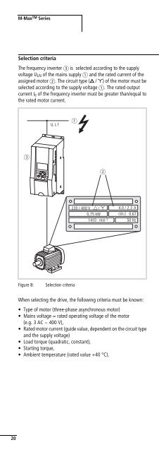
- Page 20 and 21: M-Max TM Series04/10 MN04020001Z-EN
- Page 23 and 24: 04/10 MN04020001Z-EN FeaturesR+R-aL
- Page 25 and 26: 04/10 MN04020001Z-EN Proper useProp
- Page 27 and 28: 04/10 MN04020001Z-EN2 EngineeringIn
- Page 29 and 30: 04/10 MN04020001Z-EN Electrical pow
- Page 31 and 32: 04/10 MN04020001Z-EN EMC measuresMa
- Page 33 and 34: 04/10 MN04020001Z-EN Motor and Appl
- Page 35 and 36: l04/10 MN04020001Z-EN3 Installation
- Page 37 and 38: 04/10 MN04020001Z-EN Installation i
- Page 39 and 40: 04/10 MN04020001Z-EN EMC installati
- Page 41 and 42: .04/10 MN04020001Z-EN Electrical In
- Page 43 and 44: 04/10 MN04020001Z-EN Electrical Ins
- Page 45: 04/10 MN04020001Z-EN Electrical Ins
- Page 51: 04/10 MN04020001Z-EN Electrical Ins
- Page 54: Installation04/10 MN04020001Z-ENBlo
- Page 58 and 59: 5404/10 MN04020001Z-EN
- Page 60 and 61: Operation04/10 MN04020001Z-ENOperat
- Page 62 and 63: Operation04/10 MN04020001Z-ENREADYR
- Page 64 and 65: Operation04/10 MN04020001Z-ENBrief
- Page 66 and 67: 6204/10 MN04020001Z-EN
- Page 68 and 69: Error and Warning Messages04/10 MN0
- Page 70 and 71: Error and Warning Messages04/10 MN0
- Page 72 and 73: Parameters04/10 MN04020001Z-ENDispl
- Page 74 and 75: Parameters04/10 MN04020001Z-ENSeque
- Page 76 and 77: Parameters04/10 MN04020001Z-ENQuick
- Page 78 and 79: Parameters04/10 MN04020001Z-ENThe f
- Page 80 and 81: Parameters04/10 MN04020001Z-ENPNU I
- Page 82 and 83: lParameters04/10 MN04020001Z-ENDigi
- Page 84 and 85: Parameters04/10 MN04020001Z-ENPNU I
- Page 86 and 87: Parameters04/10 MN04020001Z-ENPNU I
- Page 88 and 89: Parameters04/10 MN04020001Z-ENDigit
- Page 90 and 91: Parameters04/10 MN04020001Z-ENPNU I
- Page 92 and 93: Parameters04/10 MN04020001Z-ENDrive
- Page 94 and 95: Parameters04/10 MN04020001Z-ENPNU I
- Page 96 and 97:
Parameters04/10 MN04020001Z-ENPNU I
- Page 98 and 99:
Parameters04/10 MN04020001Z-ENMotor
- Page 100 and 101:
Parameters04/10 MN04020001Z-ENPNU I
- Page 102 and 103:
Parameters04/10 MN04020001Z-ENPNU I
- Page 104 and 105:
Parameters04/10 MN04020001Z-ENPID c
- Page 106 and 107:
Parameters04/10 MN04020001Z-ENPNU I
- Page 108 and 109:
Parameters04/10 MN04020001Z-ENFixed
- Page 110 and 111:
Parameters04/10 MN04020001Z-ENSeque
- Page 112 and 113:
Parameters04/10 MN04020001Z-ENExamp
- Page 114 and 115:
Parameters04/10 MN04020001Z-ENExamp
- Page 116 and 117:
Parameters04/10 MN04020001Z-ENU[%]P
- Page 118 and 119:
Parameters04/10 MN04020001Z-ENOn th
- Page 120 and 121:
Parameters04/10 MN04020001Z-ENBraki
- Page 122 and 123:
Parameters04/10 MN04020001Z-ENPNU I
- Page 124 and 125:
Parameters04/10 MN04020001Z-ENMecha
- Page 126 and 127:
Parameters04/10 MN04020001Z-ENPNU I
- Page 128 and 129:
Parameters04/10 MN04020001Z-ENSecon
- Page 130 and 131:
Parameters04/10 MN04020001Z-ENThe f
- Page 132 and 133:
Parameters04/10 MN04020001Z-ENSyste
- Page 134 and 135:
Parameters04/10 MN04020001Z-ENOpera
- Page 136 and 137:
Parameters04/10 MN04020001Z-ENSetpo
- Page 138 and 139:
13404/10 MN04020001Z-EN
- Page 140 and 141:
Serial interface (Modbus RTU)04/10
- Page 142 and 143:
Serial interface (Modbus RTU)04/10
- Page 144 and 145:
Serial interface (Modbus RTU)04/10
- Page 146 and 147:
Serial interface (Modbus RTU)04/10
- Page 148 and 149:
Serial interface (Modbus RTU)04/10
- Page 150 and 151:
14604/10 MN04020001Z-EN
- Page 152 and 153:
Appendix04/10 MN04020001Z-ENDevice
- Page 154 and 155:
Appendix04/10 MN04020001Z-ENDevice
- Page 156 and 157:
Appendix04/10 MN04020001Z-ENTable 1
- Page 158 and 159:
Appendix04/10 MN04020001Z-ENMMX-NET
- Page 160 and 161:
Appendix04/10 MN04020001Z-ENXMX-NET
- Page 162 and 163:
Appendix04/10 MN04020001Z-ENTable 1
- Page 164 and 165:
Appendix04/10 MN04020001Z-ENPart no
- Page 166 and 167:
Appendix04/10 MN04020001Z-ENTable 1
- Page 168 and 169:
Appendix04/10 MN04020001Z-ENDimensi
- Page 170 and 171:
OKAppendix04/10 MN04020001Z-ENh Cau
- Page 172 and 173:
Appendix04/10 MN04020001Z-ENTable 1
- Page 174 and 175:
Appendix04/10 MN04020001Z-ENPart no
- Page 176 and 177:
Appendix04/10 MN04020001Z-ENTable 2
- Page 178 and 179:
Appendix04/10 MN04020001Z-ENDF51-Ma
- Page 180 and 181:
Appendix04/10 MN04020001Z-ENList of
- Page 182 and 183:
Appendix04/10 MN04020001Z-ENPNU ID
- Page 184 and 185:
Appendix04/10 MN04020001Z-ENPNU ID
- Page 186 and 187:
Appendix04/10 MN04020001Z-ENPNU ID
- Page 188 and 189:
Appendix04/10 MN04020001Z-ENPNU ID
- Page 190 and 191:
Appendix04/10 MN04020001Z-ENPNU ID
- Page 192 and 193:
Appendix04/10 MN04020001Z-ENPNU ID
- Page 194 and 195:
Appendix04/10 MN04020001Z-ENPNU ID
- Page 196 and 197:
19204/10 MN04020001Z-EN
- Page 198 and 199:
Index04/10 MN04020001Z-ENM-Max . .