Datasheet GRR - PMCCatalogue
Datasheet GRR - PMCCatalogue
Datasheet GRR - PMCCatalogue

You also want an ePaper? Increase the reach of your titles
YUMPU automatically turns print PDFs into web optimized ePapers that Google loves.
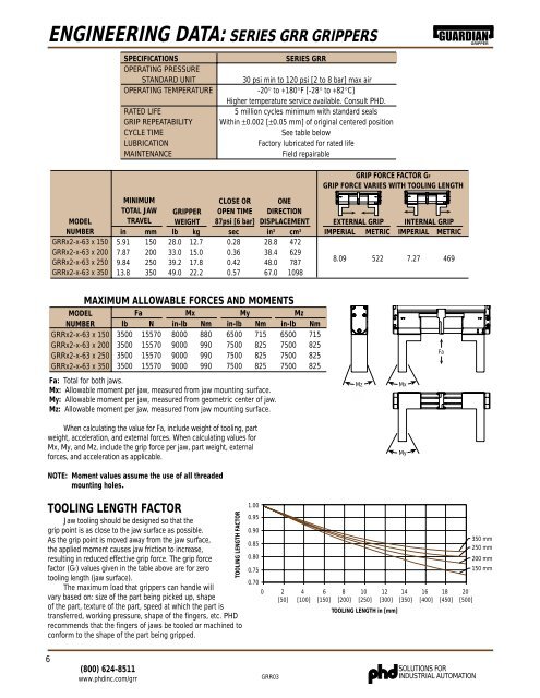
ENGINEERING DATA: SERIES <strong>GRR</strong> GRIPPERSGUARDIAN GRIPPERSPECIFICATIONSOPERATING PRESSURESTANDARD UNITOPERATING TEMPERATURERATED LIFEGRIP REPEATABILITYCYCLE TIMELUBRICATIONMAINTENANCESERIES <strong>GRR</strong>30 psi min to 120 psi [2 to 8 bar] max air-20° to +180°F [-28° to +82°C]Higher temperature service available. Consult PHD.5 million cycles minimum with standard sealsWithin ±0.002 [±0.05 mm] of original centered positionSee table belowFactory lubricated for rated lifeField repairableGRIP FORCE FACTOR GFGRIP FORCE VARIES WITH TOOLING LENGTHMODELNUMBER<strong>GRR</strong>x2-x-63 x 150<strong>GRR</strong>x2-x-63 x 200<strong>GRR</strong>x2-x-63 x 250<strong>GRR</strong>x2-x-63 x 350MINIMUMTOTAL JAWTRAVELin5.917.879.8413.8mm150200250350GRIPPERWEIGHTlb28.033.039.249.0kg12.715.017.822.2CLOSE OROPEN TIME87psi [6 bar]sec0.280.360.420.57ONEDIRECTIONDISPLACEMENTin 3 cm 328.8 47238.4 62948.0 78767.0 1098EXTERNAL GRIPIMPERIAL METRIC8.09 522INTERNAL GRIPIMPERIAL METRIC7.27 469MODELNUMBER<strong>GRR</strong>x2-x-63 x 150<strong>GRR</strong>x2-x-63 x 200<strong>GRR</strong>x2-x-63 x 250<strong>GRR</strong>x2-x-63 x 350MAXIMUM ALLOWABLE FORCES AND MOMENTSFalb N3500 155703500 155703500 155703500 15570Mxin-lb8000900090009000Nm880990990990Myin-lb6500750075007500Nm715825825825Mzin-lb6500750075007500Nm715825825825FaFa: Total for both jaws.Mx: Allowable moment per jaw, measured from jaw mounting surface.My: Allowable moment per jaw, measured from geometric center of jaw.Mz: Allowable moment per jaw, measured from jaw mounting surface.MzMxWhen calculating the value for Fa, include weight of tooling, partweight, acceleration, and external forces. When calculating values forMx, My, and Mz, include the grip force per jaw, part weight, externalforces, and acceleration as applicable.MyNOTE: Moment values assume the use of all threadedmounting holes.TOOLING LENGTH FACTORJaw tooling should be designed so that thegrip point is as close to the jaw surface as possible.As the grip point is moved away from the jaw surface,the applied moment causes jaw friction to increase,resulting in reduced effective grip force. The grip forcefactor (GF) values given in the table above are for zerotooling length (jaw surface).The maximum load that grippers can handle willvary based on: size of the part being picked up, shapeof the part, texture of the part, speed at which the part istransferred, working pressure, shape of the fingers, etc. PHDrecommends that the fingers of jaws be tooled or machined toconform to the shape of the part being gripped.TOOLING LENGTH FACTOR1.000.950.90350 mm0.85250 mm0.80200 mm0.75150 mm0.700 2 4 6 8 10 12 14 16 18 20[50] [100] [150] [200] [250] [300] [350] [400] [450] [500]TOOLING LENGTH in [mm]6(800) 624-8511www.phdinc.com/grr<strong>GRR</strong>03SOLUTIONS FORINDUSTRIAL AUTOMATION