316 Stainless Steel, Bronze and Cast Iron Models - SHURflo Industrial
316 Stainless Steel, Bronze and Cast Iron Models - SHURflo Industrial
316 Stainless Steel, Bronze and Cast Iron Models - SHURflo Industrial

You also want an ePaper? Increase the reach of your titles
YUMPU automatically turns print PDFs into web optimized ePapers that Google loves.
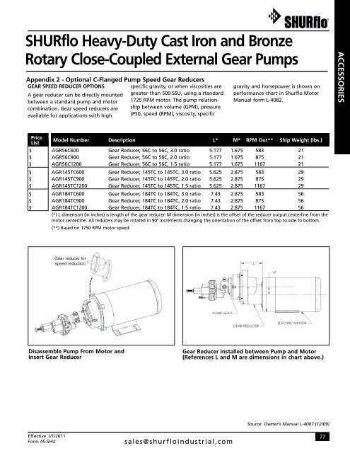
<strong>SHURflo</strong> Heavy-Duty <strong>Cast</strong> <strong>Iron</strong> <strong>and</strong> <strong>Bronze</strong>Rotary Close-Coupled External Gear PumpsAppendix 2 - Optional C-Flanged Pump Speed Gear ReducersGEAR SPEED REDUCER OPTIONSspecific gravity, or when viscosities areA gear reducer can be directly mounted greater than 500 SSU, using a st<strong>and</strong>ardbetween a st<strong>and</strong>ard pump <strong>and</strong> motor 1725 RPM motor. The pump relationshipbetween volume (GPM), pressurecombination. Gear speed reducers areavailable for applications with high (PSI), speed (RPM), viscosity, specificgravity <strong>and</strong> horsepower is shown onperformance chart in Shurflo MotorManual form L-4082.ACCESSORIESPriceList$$$$$$$$$Model Number Description L* M* RPM Out** Ship Weight (Ibs.)AGR56C600 Gear Reducer, 56C to 56C, 3.0 ratio 5.177 1.675 583 21AGR56C900 Gear Reducer, 56C to 56C, 2.0 ratio 5.177 1.675 875 21AGR56C1200 Gear Reducer, 56C to 56C, 1.5 ratio 5.177 1.675 1167 21AGR145TC600 Gear Reducer, 145TC to 145TC, 3.0 ratio 5.625 2.875 583 29AGR145TC900 Gear Reducer, 145TC to 145TC, 2.0 ratio 5.625 2.875 875 29AGR145TC1200 Gear Reducer, 145TC to 145TC, 1.5 ratio 5.625 2.875 1167 29AGR184TC600 Gear Reducer, 184TC to 184TC, 3.0 ratio 7.43 2.875 583 56AGR184TC900 Gear Reducer, 184TC to 184TC, 2.0 ratio 7.43 2.875 875 56AGR184TC1200 Gear Reducer, 184TC to 184TC, 1.5 ratio 7.43 2.875 1167 56(*) L dimension (in inches) is length of the gear reducer. M dimension (in inches) is the offset of the reducer output centerline from themotor centerline. All reducers may be rotated in 90° increments changing the orientation of the offset from top to side to bottom.(**) Based on 1750 RPM motor speed.Disassemble Pump From Motor <strong>and</strong>Insert Gear ReducerGear Reducer Installed between Pump <strong>and</strong> Motor(References L <strong>and</strong> M are dimensions in chart above.)Effective 1/1/2011Form 45-SHUsales@shurfloindustrial.comSource: Owner’s Manual L-4087 (12/09)77