Digital dimmable ballasts for fluorescent lamps EXCEL ... - Tridonic
Digital dimmable ballasts for fluorescent lamps EXCEL ... - Tridonic
Digital dimmable ballasts for fluorescent lamps EXCEL ... - Tridonic
- No tags were found...

You also want an ePaper? Increase the reach of your titles
YUMPU automatically turns print PDFs into web optimized ePapers that Google loves.
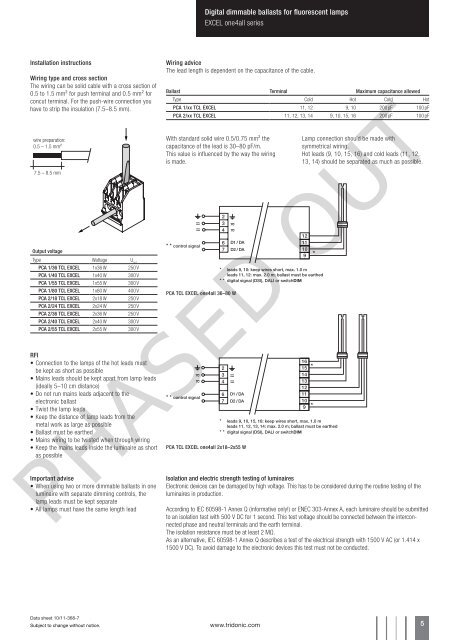
<strong>Digital</strong> <strong>dimmable</strong> <strong>ballasts</strong> <strong>for</strong> <strong>fluorescent</strong> <strong>lamps</strong><strong>EXCEL</strong> one4all seriesInstallation instructionsWiring type and cross sectionThe wiring can be solid cable with a cross section of0.5 to 1.5 mm² <strong>for</strong> push terminal and 0.5 mm² <strong>for</strong>concut terminal. For the push-wire connection youhave to strip the insulation (7.5–8.5 mm).wire preparation:0.5 – 1.5 mm²7.5 – 8.5 mmOutput voltageType Wattage U outPCA 1/36 TCL <strong>EXCEL</strong> 1x36 W 250 VPCA 1/40 TCL <strong>EXCEL</strong> 1x40 W 300 VPCA 1/55 TCL <strong>EXCEL</strong> 1x55 W 300 VPCA 1/80 TCL <strong>EXCEL</strong> 1x80 W 400 VPCA 2/18 TCL <strong>EXCEL</strong> 2x18 W 250 VPCA 2/24 TCL <strong>EXCEL</strong> 2x24 W 250 VPCA 2/36 TCL <strong>EXCEL</strong> 2x36 W 250 VPCA 2/40 TCL <strong>EXCEL</strong> 2x40 W 300 VPCA 2/55 TCL <strong>EXCEL</strong> 2x55 W 300 VRFI• Connection to the <strong>lamps</strong> of the hot leads mustbe kept as short as possible• Mains leads should be kept apart from lamp leads(ideally 5–10 cm distance)• Do not run mains leads adjacent to theelectronic ballast• Twist the lamp leads• Keep the distance of lamp leads from themetal work as large as possible• Ballast must be earthed• Mains wiring to be twisted when through wiring• Keep the mains leads inside the luminaire as shortas possibleImportant advise• When using two or more <strong>dimmable</strong> <strong>ballasts</strong> in oneluminaire with separate dimming controls, thelamp leads must be kept separate• All <strong>lamps</strong> must have the same length leadWiring adviceThe lead length is dependent on the capacitance of the cable.Ballast Terminal Maximum capacitance allowedType Cold Hot Cold HotPCA 1/xx TCL <strong>EXCEL</strong> 11, 12 9, 10 200 pF 100 pFPCA 2/xx TCL <strong>EXCEL</strong> 11, 12, 13, 14 9, 10, 15, 16 200 pF 100 pFWith standard solid wire 0.5/0.75 mm² thecapacitance of the lead is 30–80 pF/m.This value is influenced by the way the wiringis made.* * control signal23467PCA TCL <strong>EXCEL</strong> one4all 36–80 W* * control signalD1 / DAD2 / DA1211109* leads 9, 10: keep wires short, max. 1.0 mleads 11, 12: max. 2.0 m; ballast must be earthed* * digital signal (DSI), DALI or switchDIM23467D1 / DAD2 / DAPCA TCL <strong>EXCEL</strong> one4all 2x18–2x55 W161514131211109* leads 9, 10, 15, 16: keep wires short, max. 1.0 mleads 11, 12, 13, 14: max. 2.0 m; ballast must be earthed* * digital signal (DSI), DALI or switchDIMLamp connection should be made withsymmetrical wiring.Hot leads (9, 10, 15, 16) and cold leads (11, 12,13, 14) should be separated as much as possible.PHASED OUTIsolation and electric strength testing of luminairesElectronic devices can be damaged by high voltage. This has to be considered during the routine testing of theluminaires in production.According to IEC 60598-1 Annex Q (in<strong>for</strong>mative only!) or ENEC 303-Annex A, each luminaire should be submittedto an isolation test with 500 V DC <strong>for</strong> 1 second. This test voltage should be connected between the interconnectedphase and neutral terminals and the earth terminal.The isolation resistance must be at least 2 MΩ.As an alternative, IEC 60598-1 Annex Q describes a test of the electrical strength with 1500 V AC (or 1.414 x1500 V DC). To avoid damage to the electronic devices this test must not be conducted.Data sheet 10/11-368-7Subject to change without notice.www.tridonic.com 5