Symbol LS3408 Product Reference Guide - Miles Data Technologies
Symbol LS3408 Product Reference Guide - Miles Data Technologies
Symbol LS3408 Product Reference Guide - Miles Data Technologies

Create successful ePaper yourself
Turn your PDF publications into a flip-book with our unique Google optimized e-Paper software.
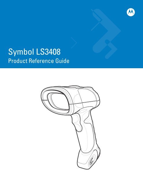
<strong>Symbol</strong> <strong>LS3408</strong><strong>Product</strong> <strong>Reference</strong> <strong>Guide</strong>
<strong>Symbol</strong> <strong>LS3408</strong><strong>Product</strong> <strong>Reference</strong> <strong>Guide</strong>72E-67133-03Revision AOctober 2008
ii<strong>Symbol</strong> <strong>LS3408</strong> <strong>Product</strong> <strong>Reference</strong> <strong>Guide</strong>© 2007-2008 by Motorola, Inc. All rights reserved.No part of this publication may be reproduced or used in any form, or by any electrical or mechanical means,without permission in writing from Motorola. This includes electronic or mechanical means, such asphotocopying, recording, or information storage and retrieval systems. The material in this manual is subject tochange without notice.The software is provided strictly on an “as is” basis. All software, including firmware, furnished to the user is ona licensed basis. Motorola grants to the user a non-transferable and non-exclusive license to use eachsoftware or firmware program delivered hereunder (licensed program). Except as noted below, such licensemay not be assigned, sublicensed, or otherwise transferred by the user without prior written consent ofMotorola. No right to copy a licensed program in whole or in part is granted, except as permitted undercopyright law. The user shall not modify, merge, or incorporate any form or portion of a licensed program withother program material, create a derivative work from a licensed program, or use a licensed program in anetwork without written permission from Motorola. The user agrees to maintain Motorola’s copyright notice onthe licensed programs delivered hereunder, and to include the same on any authorized copies it makes, inwhole or in part. The user agrees not to decompile, disassemble, decode, or reverse engineer any licensedprogram delivered to the user or any portion thereof.Motorola reserves the right to make changes to any software or product to improve reliability, function, ordesign.Motorola does not assume any product liability arising out of, or in connection with, the application or use ofany product, circuit, or application described herein.No license is granted, either expressly or by implication, estoppel, or otherwise under any Motorola, Inc.,intellectual property rights. An implied license only exists for equipment, circuits, and subsystems contained inMotorola products.MOTOROLA and the Stylized M Logo and <strong>Symbol</strong> and the <strong>Symbol</strong> logo are registered in the US Patent &Trademark Office. Bluetooth is a registered trademark of Bluetooth SIG. Microsoft, Windows and ActiveSyncare either registered trademarks or trademarks of Microsoft Corporation. All other product or service namesare the property of their respective owners.Motorola, Inc.One Motorola PlazaHoltsville, New York 11742-1300http://www.motorola.com/enterprisemobilityWarrantyFor the complete Motorola hardware product warranty statement, go to:http://www.motorola.com/enterprisemobility/warrantyPatentsThis product is covered by one or more patents. For patent information go to:http://www.motorola.com/enterprisemobility/patents
iiiRevision HistoryChanges to the original manual are listed below:Change Date Description-01 Rev A 2/2004 Initial release.-02 Rev A 10/2007 Motorola rebranding; add new UPC/EAN Supplemental options, User-Programmable Supplementals option, and Bookland ISBN format.-03 Rev A 10/2008 Add custom defaults option, add parameter scanning option, remove IBM XT barcode and keyboard from Keyboard Wedge section, add French Belgian countrycodes, change UCC/EAN-128 code type to GS1-128, add specific string search andnew move cursor options in ADF chapter.
iv<strong>Symbol</strong> <strong>LS3408</strong> <strong>Product</strong> <strong>Reference</strong> <strong>Guide</strong>
Table of ContentsAbout This <strong>Guide</strong>Introduction .................................................................................................................... xiiiChapter Descriptions ..................................................................................................... xiiiService Information........................................................................................................ xvChapter 1: Getting StartedIntroduction ................................................................................................................... 1-1Unpacking the Scanner ................................................................................................ 1-2Setting Up the Scanner ................................................................................................. 1-3Installing the Interface Cable .................................................................................. 1-3Connecting Power (if required) ............................................................................... 1-4Connecting a Synapse Cable Interface .................................................................. 1-5Removing the Interface Cable ................................................................................ 1-5Configuring the Scanner ......................................................................................... 1-5Chapter 2: ScanningIntroduction ................................................................................................................... 2-1Beeper Definitions ........................................................................................................ 2-2LED Definitions ............................................................................................................. 2-3Scanning in Hand-Held Mode ....................................................................................... 2-3Aiming ..................................................................................................................... 2-4Scanning in Presentation Mode .................................................................................... 2-5Decode Zone ................................................................................................................ 2-6Chapter 3: Maintenance and Technical SpecificationsIntroduction ................................................................................................................... 3-1Maintenance ................................................................................................................. 3-1Troubleshooting ............................................................................................................ 3-2Technical Specifications ............................................................................................... 3-4Scanner Signal Descriptions ......................................................................................... 3-6
vi<strong>Symbol</strong> <strong>LS3408</strong> <strong>Product</strong> <strong>Reference</strong> <strong>Guide</strong>Chapter 4: User PreferencesIntroduction ................................................................................................................... 4-1Scanning Sequence Examples ..................................................................................... 4-1Errors While Scanning .................................................................................................. 4-2User Preferences Default Parameters .......................................................................... 4-2User Preferences .......................................................................................................... 4-3Set Default Parameter ............................................................................................ 4-3Parameter Scanning ............................................................................................... 4-4Beeper Tone ........................................................................................................... 4-4Beeper Volume ....................................................................................................... 4-5Power Mode ............................................................................................................ 4-5Laser On Time ........................................................................................................ 4-6Beep After Good Decode ........................................................................................ 4-6Trigger Mode ........................................................................................................... 4-7Aim Duration ........................................................................................................... 4-8Chapter 5: Keyboard Wedge InterfaceIntroduction ................................................................................................................... 5-1Connecting a Keyboard Wedge Interface ..................................................................... 5-2Keyboard Wedge Default Parameters .......................................................................... 5-3Keyboard Wedge Host Types ....................................................................................... 5-4Keyboard Wedge Host Types ................................................................................. 5-4Keyboard Wedge Country Types (Country Codes) ................................................ 5-5Ignore Unknown Characters ................................................................................... 5-7Keystroke Delay ...................................................................................................... 5-7Intra-Keystroke Delay ............................................................................................. 5-8Alternate Numeric Keypad Emulation ..................................................................... 5-8Caps Lock On ......................................................................................................... 5-8Caps Lock Override ................................................................................................ 5-9Convert Wedge <strong>Data</strong> .............................................................................................. 5-9Function Key Mapping ............................................................................................ 5-10FN1 Substitution ..................................................................................................... 5-10Send Make and Break ............................................................................................ 5-10Keyboard Maps ....................................................................................................... 5-11ASCII Character Set ..................................................................................................... 5-13Chapter 6: RS-232 InterfaceIntroduction ................................................................................................................... 6-1Connecting an RS-232 Interface .................................................................................. 6-2RS-232 Default Parameters .......................................................................................... 6-3RS-232 Host Parameters .............................................................................................. 6-4RS-232 Host Types ................................................................................................. 6-6Baud Rate ............................................................................................................... 6-7Parity ....................................................................................................................... 6-8Check Receive Errors ............................................................................................. 6-9Stop Bit Select ........................................................................................................ 6-10<strong>Data</strong> Bits ................................................................................................................. 6-10Hardware Handshaking .......................................................................................... 6-11
Table of ContentsviiSoftware Handshaking ............................................................................................ 6-13Host Serial Response Time-out .............................................................................. 6-15RTS Line State ........................................................................................................ 6-16Beep on ....................................................................................................... 6-16Intercharacter Delay ................................................................................................ 6-17Nixdorf Mode A/B and OPOS/JPOS Beep/LED Options ........................................ 6-18Ignore Unknown Characters ................................................................................... 6-18ASCII / Character Set ................................................................................................... 6-19Chapter 7: USB InterfaceIntroduction ................................................................................................................... 7-1Connecting a USB Interface ......................................................................................... 7-2USB Default Parameters .............................................................................................. 7-3USB Host Parameters .................................................................................................. 7-4USB Device Type .................................................................................................... 7-4USB Country Keyboard Types (Country Codes) .................................................... 7-5USB Keystroke Delay ............................................................................................. 7-7USB CAPS Lock Override ...................................................................................... 7-8USB Ignore Unknown Characters ........................................................................... 7-8Emulate Keypad ...................................................................................................... 7-9USB Keyboard FN 1 Substitution ............................................................................ 7-9Function Key Mapping ............................................................................................ 7-10Simulated Caps Lock .............................................................................................. 7-10Convert Case .......................................................................................................... 7-11ASCII Character Set ..................................................................................................... 7-12Chapter 8: IBM 468X/469X InterfaceIntroduction ................................................................................................................... 8-1Connecting to an IBM 468X/469X Host ........................................................................ 8-2IBM Default Parameters ............................................................................................... 8-3IBM 468X/469X Host Parameters ................................................................................. 8-4Port Address ........................................................................................................... 8-4Convert Unknown to Code 39 ................................................................................. 8-4Chapter 9: Wand Emulation InterfaceIntroduction ................................................................................................................... 9-1Connecting a Wand Emulation Interface ...................................................................... 9-2Wand Emulation Default Parameters ........................................................................... 9-3Wand Emulation Host Parameters ............................................................................... 9-4Wand Emulation Host Types .................................................................................. 9-4Leading Margin (Quiet Zone) .................................................................................. 9-5Polarity .................................................................................................................... 9-5Ignore Unknown Characters ................................................................................... 9-6Convert All Bar Codes to Code 39 .......................................................................... 9-7Convert Code 39 to Full ASCII ............................................................................... 9-8
viii<strong>Symbol</strong> <strong>LS3408</strong> <strong>Product</strong> <strong>Reference</strong> <strong>Guide</strong>Chapter 10: Scanner Emulation InterfaceIntroduction ................................................................................................................... 10-1Connecting Using Scanner Emulation .......................................................................... 10-2Scanner Emulation Default Parameters ....................................................................... 10-3Scanner Emulation Host ............................................................................................... 10-4Scanner Emulation Host Parameters ........................................................................... 10-4Beep Style ............................................................................................................... 10-4Parameter Pass-Through ........................................................................................ 10-5Convert Newer Code Types .................................................................................... 10-6Module Width .......................................................................................................... 10-6Convert All Bar Codes to Code 39 .......................................................................... 10-7Code 39 Full ASCII Conversion .............................................................................. 10-7Transmission Timeout ............................................................................................. 10-8Ignore Unknown Characters ................................................................................... 10-9Leading Margin ....................................................................................................... 10-10Check For Decode LED .......................................................................................... 10-11Chapter 11: 123ScanIntroduction ................................................................................................................... 11-1Communication with 123Scan ...................................................................................... 11-1123Scan Parameter ...................................................................................................... 11-2Chapter 12: <strong>Symbol</strong>ogiesIntroduction ................................................................................................................... 12-1Scanning Sequence Examples ..................................................................................... 12-1Errors While Scanning .................................................................................................. 12-1<strong>Symbol</strong>ogy Default Parameters .................................................................................... 12-2UPC/EAN ...................................................................................................................... 12-5Enable/Disable UPC-A ............................................................................................ 12-5Enable/Disable UPC-E ............................................................................................ 12-5Enable/Disable UPC-E1 .......................................................................................... 12-6Enable/Disable EAN-13 .......................................................................................... 12-6Enable/Disable EAN-8 ............................................................................................ 12-7Enable/Disable Bookland EAN ............................................................................... 12-7Decode UPC/EAN/JAN Supplementals .................................................................. 12-8User-Programmable Supplementals ....................................................................... 12-11UPC/EAN/JAN Supplemental Redundancy ............................................................ 12-11Transmit UPC-A/UPC-E/UPC-E1 Check Digit ........................................................ 12-12UPC-A Preamble .................................................................................................... 12-13UPC-E Preamble .................................................................................................... 12-14UPC-E1 Preamble .................................................................................................. 12-15Convert UPC-E to UPC-A ....................................................................................... 12-16Convert UPC-E1 to UPC-A ..................................................................................... 12-16EAN-8/JAN-8 Extend .............................................................................................. 12-17Bookland ISBN Format ........................................................................................... 12-17Code 128 ...................................................................................................................... 12-18Enable/Disable Code 128 ....................................................................................... 12-18Enable/Disable GS1-128 ........................................................................................ 12-18
Table of ContentsixEnable/Disable ISBT 128 ........................................................................................ 12-19Code 39 ........................................................................................................................ 12-20Enable/Disable Code 39 ......................................................................................... 12-20Enable/Disable Trioptic Code 39 ............................................................................ 12-20Convert Code 39 to Code 32 .................................................................................. 12-21Code 32 Prefix ........................................................................................................ 12-21Set Lengths for Code 39 ......................................................................................... 12-22Code 39 Check Digit Verification ............................................................................ 12-23Transmit Code 39 Check Digit ................................................................................ 12-23Code 39 Full ASCII Conversion .............................................................................. 12-24Code 93 ........................................................................................................................ 12-25Enable/Disable Code 93 ......................................................................................... 12-25Set Lengths for Code 93 ......................................................................................... 12-25Code 11 ........................................................................................................................ 12-27Code 11 .................................................................................................................. 12-27Set Lengths for Code 11 ......................................................................................... 12-27Code 11 Check Digit Verification ............................................................................ 12-29Transmit Code 11 Check Digits .............................................................................. 12-30Interleaved 2 of 5 (I 2 of 5) ............................................................................................ 12-31Enable/Disable Interleaved 2 of 5 ........................................................................... 12-31Set Lengths for Interleaved 2 of 5 ........................................................................... 12-31I 2 of 5 Check Digit Verification ............................................................................... 12-33Transmit I 2 of 5 Check Digit ................................................................................... 12-33Convert I 2 of 5 to EAN-13 ...................................................................................... 12-34Discrete 2 of 5 (D 2 of 5) ............................................................................................... 12-35Enable/Disable Discrete 2 of 5 ................................................................................ 12-35Set Lengths for Discrete 2 of 5 ............................................................................... 12-35Codabar (NW - 7) ......................................................................................................... 12-37Enable/Disable Codabar ......................................................................................... 12-37Set Lengths for Codabar ......................................................................................... 12-37CLSI Editing ............................................................................................................ 12-39NOTIS Editing ......................................................................................................... 12-39MSI ............................................................................................................................... 12-40Enable/Disable MSI ................................................................................................ 12-40Set Lengths for MSI ................................................................................................ 12-40MSI Check Digits .................................................................................................... 12-42Transmit MSI Check Digit(s) ................................................................................... 12-42MSI Check Digit Algorithm ...................................................................................... 12-43GS1 <strong>Data</strong>Bar (formerly Reduced Space <strong>Symbol</strong>ogy) ................................................... 12-44GS1 <strong>Data</strong>Bar ........................................................................................................... 12-44GS1 <strong>Data</strong>Bar Limited .............................................................................................. 12-44Convert GS1 <strong>Data</strong>Bar to UPC/EAN ........................................................................ 12-45Redundancy Level ........................................................................................................ 12-46Redundancy Level 1 ............................................................................................... 12-46Redundancy Level 2 ............................................................................................... 12-46Redundancy Level 3 ............................................................................................... 12-47Redundancy Level 4 ............................................................................................... 12-47Security Level ............................................................................................................... 12-48Security Level 0 ...................................................................................................... 12-48Security Level 1 ...................................................................................................... 12-48
x<strong>Symbol</strong> <strong>LS3408</strong> <strong>Product</strong> <strong>Reference</strong> <strong>Guide</strong>Security Level 2 ...................................................................................................... 12-49Security Level 3 ...................................................................................................... 12-49Bi-directional Redundancy ............................................................................................ 12-49Chapter 13: Miscellaneous Scanner OptionsIntroduction ................................................................................................................... 13-1Scanning Sequence Examples ..................................................................................... 13-1Errors While Scanning .................................................................................................. 13-1Miscellaneous Default Parameters ............................................................................... 13-2Miscellaneous Scanner Parameters ............................................................................. 13-3Transmit Code ID Character ................................................................................... 13-3Scan Angle .............................................................................................................. 13-4Prefix/Suffix Values ................................................................................................. 13-4Scan <strong>Data</strong> Transmission Format ............................................................................ 13-5FN1 Substitution Values ......................................................................................... 13-7Transmit “No Read” Message ................................................................................. 13-7Synapse Interface ................................................................................................... 13-8Chapter 14: Advanced <strong>Data</strong> FormattingIntroduction ................................................................................................................... 14-1Rules: Criteria Linked to Actions ................................................................................... 14-1Using ADF Bar Codes .................................................................................................. 14-2ADF Bar Code Menu Example ..................................................................................... 14-2Rule 1: The Code 128 Scanning Rule .................................................................... 14-3Rule 2: The UPC Scanning Rule ............................................................................ 14-3Alternate Rule Sets ................................................................................................. 14-3Rules Hierarchy (in Bar Codes) .............................................................................. 14-5Default Rules .......................................................................................................... 14-5Special Commands ....................................................................................................... 14-6Pause Duration ....................................................................................................... 14-6Begin New Rule ...................................................................................................... 14-6Save Rule ............................................................................................................... 14-6Erase ....................................................................................................................... 14-7Quit Entering Rules ................................................................................................. 14-7Disable Rule Set ..................................................................................................... 14-8Criteria .......................................................................................................................... 14-9Code Types ............................................................................................................. 14-9Code Lengths .......................................................................................................... 14-13Message Containing A Specific <strong>Data</strong> String ........................................................... 14-18Actions .......................................................................................................................... 14-23Send <strong>Data</strong> ............................................................................................................... 14-23Setup Field(s) .......................................................................................................... 14-27Modify <strong>Data</strong> ............................................................................................................. 14-34Pad <strong>Data</strong> with Spaces ............................................................................................. 14-35Pad <strong>Data</strong> with Zeros ............................................................................................... 14-40Beeps ...................................................................................................................... 14-45Send Keystroke (Control Characters and Keyboard Characters) ........................... 14-46Send Right Control Key .......................................................................................... 14-86
Table of ContentsxiSend Graphic User Interface (GUI) Characters ...................................................... 14-87Turn On/Off Rule Sets ............................................................................................ 14-93Alphanumeric Keyboard ............................................................................................... 14-95Appendix A: Standard Default ParametersAppendix B: Programming <strong>Reference</strong><strong>Symbol</strong> Code Identifiers ................................................................................................ B-1AIM Code Identifiers ..................................................................................................... B-2Appendix C: Sample Bar CodesUPC-A ........................................................................................................................... C-1UPC-E ........................................................................................................................... C-1UPC-E1 ......................................................................................................................... C-1EAN-13 ......................................................................................................................... C-2EAN-8 ........................................................................................................................... C-2Code 39 ........................................................................................................................ C-2Trioptic Code 39 ........................................................................................................... C-3Code 93 ........................................................................................................................ C-3Code 11 ........................................................................................................................ C-3Codabar ........................................................................................................................ C-4MSI ............................................................................................................................... C-4Interleaved 2 of 5 .......................................................................................................... C-4Appendix D: Numeric Bar Codes0, 1, 2 ............................................................................................................................ D-13, 4, 5, 6 ........................................................................................................................ D-27, 8, 9 ............................................................................................................................ D-3Cancel ........................................................................................................................... D-3GlossaryIndexTell Us What You Think...
xii<strong>Symbol</strong> <strong>LS3408</strong> <strong>Product</strong> <strong>Reference</strong> <strong>Guide</strong>
About This <strong>Guide</strong>IntroductionThe <strong>Symbol</strong> <strong>LS3408</strong> <strong>Product</strong> <strong>Reference</strong> <strong>Guide</strong> provides general instructions for setting up, operating, maintaining,and troubleshooting the scanner. The <strong>Symbol</strong> <strong>LS3408</strong> includes the following variations of the scanner:• <strong>LS3408</strong>-FZ20005: 1-D scanning• <strong>LS3408</strong>-ER20005: extended range 1-D scanning.Chapter Descriptions• Chapter 1, Getting Started provides a product overview and unpacking instructions.• Chapter 2, Scanning describes parts of the scanner, beeper and LED definitions, and how to use the scannerin hand-held and hands-free modes.• Chapter 3, Maintenance and Technical Specifications provides information on how to care for the scanner,troubleshooting, and technical specifications.• Chapter 4, User Preferences provides programming bar codes for selecting user preference features for thescanner.• Chapter 5, Keyboard Wedge Interface provides information for setting up the scanner for Keyboard Wedgeoperation.• Chapter 6, RS-232 Interface provides information for setting up the scanner for RS-232 operation.• Chapter 7, USB Interface provides information for setting up the scanner for USB operation.• Chapter 8, IBM 468X/469X Interface provides information for setting up the scanner with IBM 468X/469XPOS systems.• Chapter 9, Wand Emulation Interface provides information for setting up the scanner for Wand Emulationoperation.• Chapter 10, Scanner Emulation Interface provides information for setting up the scanner for ScannerEmulation operation.
xiv<strong>Symbol</strong> <strong>LS3408</strong> <strong>Product</strong> <strong>Reference</strong> <strong>Guide</strong>• Chapter 11, 123Scan (PC based scanner configuration tool) provides the bar code to scan to communicatewith the 123Scan program.• Chapter 12, <strong>Symbol</strong>ogies describes all symbology features and provides programming bar codes forselecting these features for the scanner.• Chapter 13, Miscellaneous Scanner Options includes frequently used features to customize how datatransmits to the host device.• Chapter 14, Advanced <strong>Data</strong> Formatting (ADF) describes how to customize scanned data before transmittingto the host.• Appendix A, Standard Default Parameters provides a table of all host devices and miscellaneous scannerdefaults.• Appendix B, Programming <strong>Reference</strong> provides a table of AIM code identifiers, ASCII character conversions,and keyboard maps.• Appendix C, Sample Bar Codes includes sample bar codes of various code types.• Appendix D, Numeric Bar Codes includes the numeric bar codes to scan for parameters requiring specificnumeric values.Notational ConventionsThe following conventions are used in this document:• Italics are used to highlight chapters and sections in this and related documents• Bullets (•) indicate:• action items• lists of alternatives• lists of required steps that are not necessarily sequential.• Sequential lists (e.g., those that describe step-by-step procedures) appear as numbered lists.• Throughout the programming bar code menus, asterisks (*) are used to denote default parameter settings.* Indicates Default*Baud Rate 9600Feature/OptionRelated PublicationsThe <strong>Symbol</strong> LS/DS3408 Quick Start <strong>Guide</strong> (p/n 72-67131-xx) provides general information to help you get startedwith the scanner. It includes basic setup and operation instructions.For the latest versions of the <strong>Symbol</strong> LS/DS3408 Quick Start <strong>Guide</strong> and the <strong>Symbol</strong> <strong>LS3408</strong> <strong>Product</strong> <strong>Reference</strong><strong>Guide</strong> go to: http://www.motorola.com/enterprisemobility/manuals.
About This <strong>Guide</strong> xvService InformationIf you have a problem with your equipment, contact Motorola Enterprise Mobility support for your region. Contactinformation is available at: http://www.motorola.com/enterprisemobility/contactsupport.When contacting Enterprise Mobility support, please have the following information available:• Serial number of the unit• Model number or product name• Software type and version numberMotorola responds to calls by e-mail, telephone or fax within the time limits set forth in service agreements.If your problem cannot be solved by Motorola Enterprise Mobility Support, you may need to return your equipmentfor servicing and will be given specific directions. Motorola is not responsible for any damages incurred duringshipment if the approved shipping container is not used. Shipping the units improperly can possibly void thewarranty.If you purchased your Enterprise Mobility business product from a Motorola business partner, please contact thatbusiness partner for support.
xvi<strong>Symbol</strong> <strong>LS3408</strong> <strong>Product</strong> <strong>Reference</strong> <strong>Guide</strong>
Chapter 1 Getting StartedIntroductionThe scanner combines excellent scanning performance and advanced ergonomics to provide the best value in alightweight laser scanner. Whether using it as a hand-held scanner or in presentation (hands-free) mode in a stand,the scanner ensures comfort and ease of use for extended periods of time.Figure 1-1 <strong>Symbol</strong> <strong>LS3408</strong> Scanner
1 - 2 <strong>Symbol</strong> <strong>LS3408</strong> <strong>Product</strong> <strong>Reference</strong> <strong>Guide</strong>This scanner supports:• Standard RS-232 connection to a host.• Keyboard Wedge connection to a host, which interprets scanned data as keystrokes. This interface supportsthe following international keyboards (for the Windows TM environment): North America, German, French,French Canadian, Spanish, Italian, Swedish, UK English, Japanese, and Brazilian-Portuguese.• Wand Emulation connection to a mobile computer, a controller, or host which collects the data as wand dataand decodes it.• Scanner Emulation connection to a mobile computer or a controller which collects the data and interprets itfor the host.• Connection to IBM ® 468X/469X hosts.• USB connection to a host. The scanner autodetects a USB host and defaults to the HID keyboard interfacetype. Scan programming bar codes to select other USB interface types. This interface supports the followinginternational keyboards (for the Windows environment): North America, German, French, FrenchCanadian, Spanish, Italian, Swedish, UK English, Japanese, and Brazilian-Portuguese.• Synapse capability which enables connection to a wide variety of host systems using a Synapse andSynapse adapter cable. The scanner autodetects Synapse.• Configuration via 123Scan.Unpacking the ScannerRemove the scanner from its packing and inspect it for damage. If the scanner was damaged in transit, contactMotorola Enterprise Mobility Support at one of the telephone numbers listed on page xv. KEEP THE PACKING. Itis the approved shipping container and should be used if the equipment ever needs to be returned for servicing.
Getting Started 1 - 3Setting Up the ScannerInstalling the Interface Cable1. Loosen the two screws on the cable clamp at the bottom of the scanner and gently pull the clamp away fromthe bottom of the scanner.Figure 1-2 Removing the Cable Clamp2. Open the clamp and plug the interface cable modular connector into the cable interface port on the bottom ofthe scanner handle.Figure 1-3 Inserting the Interface Cable3. Gently tug the cable to ensure the connector is properly secured.
1 - 4 <strong>Symbol</strong> <strong>LS3408</strong> <strong>Product</strong> <strong>Reference</strong> <strong>Guide</strong>4. Close the clamp, push it back into place and tighten the screws on the clamp to secure the cable into thebottom of the scanner.Figure 1-4 Closing the Cable Clamp5. Connect the other end of the interface cable to the host (see the specific host chapter for information on hostconnections).NOTEDifferent hosts require different cables. The connectors illustrated in each host chapter are examples only.The connectors may be different than those illustrated, but the steps to connect the scanner are the same.Connecting Power (if required)If the host does not provide power to the scanner, connect external power to power the scanner:1. Connect the interface cable to the bottom of the scanner, as described in Installing the Interface Cable on page1-3.2. Connect the other end of the interface cable to the host (refer to the host manual to locate the correct port).3. Plug the power supply into the power jack on the interface cable. Plug the other end of the power supply intoan AC outlet.
Getting Started 1 - 5Connecting a Synapse Cable InterfaceNOTERefer to the Synapse Interface <strong>Guide</strong> provided with the Synapse cable for detailed setup instructions.Synapse Smart Cables enable interfacing to a variety of hosts. The appropriate Synapse cable has the built-inintelligence to detect that host.To hostSynapse adapter cableSynapse Smart CableTo scannerFigure 1-5 Synapse Cable Connection1. Plug the Synapse adapter cable into the bottom of the scanner, as described in Installing the Interface Cableon page 1-3.2. Align the ‘S’ on the Synapse adapter cable with the ‘S’ on the Synapse Smart Cable and plug the cable in.3. Connect the other end of the Synapse Smart Cable to the host.Removing the Interface Cable1. Loosen the two screws on the cable clamp at the bottom of the scanner and gently pull the clamp away fromthe bottom of the scanner.2. Open the clamp and unplug the interface cable modular connector from the cable interface port on the bottomof the scanner handle. Carefully slide out the cable.3. Follow the steps for Installing the Interface Cable on page 1-3 to connect a new cable.Configuring the ScannerUse the bar codes in this manual or the 123Scan configuration program to configure the scanner. See Chapter 4,User Preferences and each host chapter for information about programming the scanner using bar code menus.See Chapter 11, 123Scan to configure the scanner using this configuration program. The 123Scan programincludes a help file.
1 - 6 <strong>Symbol</strong> <strong>LS3408</strong> <strong>Product</strong> <strong>Reference</strong> <strong>Guide</strong>
Chapter 2 ScanningIntroductionThis chapter provides beeper and LED definitions, techniques involved in scanning bar codes, general instructionsand tips about scanning, and decode zone diagrams.Tether PlateScan WindowLEDIndicatorsScan TriggerFigure 2-1 Parts
2 - 2 <strong>Symbol</strong> <strong>LS3408</strong> <strong>Product</strong> <strong>Reference</strong> <strong>Guide</strong>Beeper DefinitionsThe scanner emits different beeper sequences and patterns to indicate its status. Table 2-1 defines beepsequences that occur during both normal scanning and while programming the scanner.Table 2-1 Standard Beeper DefinitionsBeeper SequenceIndicationStandard UseShort low/short medium/short high beepsequencePower up.1 short high beep A bar code symbol was decoded (if decode beeper is enabled).4 long low beeps A transmission error was detected in a scanned symbol. The data isignored.5 long low beeps Conversion or format error.Short high/short high/short high/long lowbeep sequenceRS-232 receive error.Parameter Menu ScanningLong low/long high beep sequenceShort high/short low beep sequenceShort high/short low/short high/short lowbeep sequenceShort low/short high/short low/short highbeep sequenceIncorrect programming sequence or Cancel bar code scanned.Scanner remains in program mode.Keyboard parameter selected. Enter value using bar code keypad.Successful program exit with change in the parameter setting.Out of host parameter storage space. Scan Set Default Parameter onpage 4-3.USB only4 short high beeps Scanner did not complete initialization. Wait several seconds and scanagain.Short low/short medium/short high beepsequence after scanning a USB DeviceType.Short low/short medium/short high beepsequence occurs more than once.Communication with the bus must be established before the scannercan operate at the highest power level.The USB bus may put the scanner in a state where power to thescanner is cycled on and off more than once. This is normal andusually happens when the PC cold boots.RS-232 only1 short high beep A character is received and Beep on is enabled.
Scanning 2 - 3LED DefinitionsIn addition to beeper sequences, the scanner uses the two-color LED to indicate its status. Table 2-2 defines LEDcolors that display during scanning.Table 2-2 Standard LED DefinitionsLEDIndicationOffGreenRedThe scanner is on and ready to scan, or no power is applied to the scanner.A bar code was successfully decoded.A data transmission error occurred.Scanning in Hand-Held ModeInstall and program the scanner (see Setting Up the Scanner on page 1-3). For assistance, contact the localsupplier or Motorola Enterprise Mobility Support.1. Connect the scanner to the host (see the appropriate host chapter).2. Aim the scanner at the bar code.3. Press the scan trigger.Figure 2-2 Scanning in Hand-Held Mode4. Ensure the scan line crosses every bar and space of the symbol.RIGHTWRONG0123450123455. Upon successful decode, the scanner beeps, and the LED turns green. For more information on beeper andLED definitions, see Table 2-1 and Table 2-2.
2 - 4 <strong>Symbol</strong> <strong>LS3408</strong> <strong>Product</strong> <strong>Reference</strong> <strong>Guide</strong>AimingDo not hold the scanner directly over the bar code. Laser light reflecting directly back into the scanner from the barcode is known as specular reflection. This specular reflection can make decoding difficult.Tilt the scanner up to 65° forward or back to achieve a successful decode (Figure 2-3). Simple practice quicklyshows what tolerances to work within.65°65°Figure 2-3 Optimum Scan Angles
Scanning 2 - 5Scanning in Presentation ModeThe optional IntelliStand adds greater flexibility to scanning operation. When you insert the scanner into the stand’s“cup,” the scanner’s built-in sensor places the scanner in presentation (hands-free) mode. When you remove thescanner from the stand, it operates in its normal hand-held mode.Adjust angle ofscanner “cup”Scanner “Cup”Adjust height ofIntelliStandFigure 2-4 Inserting the Scanner in the IntelliStandTo operate the scanner in the IntelliStand:1. Connect the scanner to the host (see the appropriate host chapter for information on host connections).2. Insert the scanner into the IntelliStand by placing the front of the scanner into the stand’s “cup” (see Figure2-4).3. To scan a bar code, present the bar code and ensure the scan line crosses every bar and space of the symbol.4. Upon successful decode, the scanner beeps and the LED turns green. For more information on beeper andLED definitions, see Table 2-1 and Table 2-2.
2 - 6 <strong>Symbol</strong> <strong>LS3408</strong> <strong>Product</strong> <strong>Reference</strong> <strong>Guide</strong>Decode Zonein. cm3076.22050.8LS 3408FZNote: Typical performance at 68˚F (20˚C)on high quality Code 39 and UPC symbols.2.5"5 mil7.25"2.0"7.5 mil15.75"1.0"13 mil24"100% UPC10 25.40 010 25.4WidthofField20 mil (80%MRD)0"* 20 mil (31%MRD)26.5"39.5"2050.82.0"*40 mil55 mil4.0"*67.0"84.0"3076.2in.cm0 10 20 30 40 50 60 70 800 25.4 50.8 76.2 101.6 127.0 152.4 177.8 203.290228.6Depth of Field*Minimum distance determined by symbol length and scan angleFigure 2-5 <strong>Symbol</strong> <strong>LS3408</strong>-FZ Decode Zone
Scanning 2 - 7in.cmNote: Typical performance at 73.4˚F (23˚C)on high quality Code 39 symbols.128430.520.310.2WidthLS 3408ER0.25"7.5 mil20"2"10 mil32"3"15 mil69"04812010.220.330.5ofField3"20 mil94"in.cm0 10 20 30 40 50 60 70 80 90 1000 25.4 50.8 76.2 101.6 127.0 152.4 177.8 203.2 228.6 254.0Depth of Fieldin.cmNote: Typical performance at 73.4˚F (23˚C)on high quality Code 39 symbols.724824182.9121.961.0WidthLS 3408ER*15"55 mil180"70 mil reflective100 mil reflective365"540"0244872061.0121.9182.9ofFieldin.cm0 60 120 180 240 300 360 420 480 540 6000 152.4 304.8 457.2 609.6 762.0 914.4 1066.8 1219.2 1371.6 1524.0*Near range determined by degree of reflectivity and width of bar code.Depth of FieldFigure 2-6 <strong>Symbol</strong> <strong>LS3408</strong>-ER Decode Zone
2 - 8 <strong>Symbol</strong> <strong>LS3408</strong> <strong>Product</strong> <strong>Reference</strong> <strong>Guide</strong>
Chapter 3 Maintenance and TechnicalSpecificationsIntroductionThis chapter provides suggested scanner maintenance, troubleshooting, technical specifications, and signaldescriptions (pinouts).MaintenanceCleaning the scan window is the only maintenance required. A dirty window can affect scanning accuracy.• Do not allow any abrasive material to touch the window.• Remove any dirt particles with a damp cloth.• Wipe the window using a tissue moistened with ammonia/water.• Do not spray water or other cleaning liquids directly onto the window.
3 - 2 <strong>Symbol</strong> <strong>LS3408</strong> <strong>Product</strong> <strong>Reference</strong> <strong>Guide</strong>TroubleshootingTable 3-1 TroubleshootingProblem Possible Causes Possible SolutionsScanner emits short low/shortmedium/short high beepsequence.Nothing happens when scantrigger is pressed.Scanner emits short low/shortmedium/short high beepsequence more than once.Laser comes on, but scannerdoes not decode the bar code.Scanner emits 4 short high beepswhile attempting to scan.Scanner is powering up.No power to the scanner.Incorrect host interface cable isused.Interface/power cables areloose.Scanner is disabled.If using RS-232 Nixdorf B mode,CTS is not asserted.The USB bus may put thescanner in a state where powerto the scanner is cycled on andoff more than once.Scanner is not programmed forthe correct bar code type.Bar code symbol is unreadable.Bar code is out of range fromthe scanner.Scanner has not completedUSB initialization.Normal when scanner is plugged in.Check the system power. Ensure the powersupply is connected if the configurationrequires a power supply.Power supply is not plugged in.Ensure that correct host interface cable isused.Ensure all cable connections are secure.For Simple Serial Interface (SSI), Synapse,or IBM 468x mode, enable the scanner viathe host interface. Otherwise, see thetechnical person in charge of scanning.Assert CTS line.Normal during host reset.Ensure the scanner is programmed to readthe type of bar code being scanned.Check the symbol to ensure it is notdefaced. Try scanning test bar codes of thesame bar code type. See Appendix C,Sample Bar Codes for test bar codes.Move scanner closer to or further from barcode.Wait several seconds and scan again.
Maintenance and Technical Specifications 3 - 3Table 3-1 Troubleshooting (Continued)Problem Possible Causes Possible SolutionsBar code is decoded, but data isnot transmitted to the host.Scanned data is incorrectlydisplayed on the host.Scanner emits short high/shorthigh/short high/long low beepsequence when it is not in use.Scanner emits long low/long highbeep sequence while it is beingprogramming.Scanner emits short low/shorthigh/short low/short high beepsequence while it is beingprogramming.Scanner emits a short low/shortmedium/short high beepsequence after changing USBhost type.Scanner emits 1 short high beepwhen it is not in use.Scanner is not programmed forthe correct host type.Interface cable is loose.If 4 long low beeps are heard, atransmission error wasdetected.If 5 long low beeps are heard, aconversion or format error wasdetected.Scanner is not programmed towork with the host.RS-232 receive error.Input error or Cancel bar codescanned.Out of ADF parameter storagespace.Out of Synapse parameterstorage space.The USB bus re-establishespower to the scanner.In RS-232 mode, a character is received and Beepon option is enabled.Scan the appropriate host parameter barcodes.Ensure all cable connections are secure.Ensure the scanner's communicationparameters match the host's setting.Ensure the scanner's conversionparameters are properly configured.Ensure proper host is selected.For RS-232, ensure the scanner'scommunication parameters match the host'ssettings.For a Keyboard Wedge configuration,ensure the system is programmed for thecorrect keyboard type, and the CAPS LOCKkey is off.Ensure editing options (e.g., UPC-E toUPC-A conversion) are properlyprogrammed.Normal during host reset. Otherwise, ensurethe scanner's RS-232 parity setting matchesthe host setting.Ensure the correct numeric bar codes, thatare within range for the parameter that isbeing programmed, are being scanned.Erase all rules and re-program with shorterrules.Scan Set Synapse Defaults bar code fromthe appropriate Synapse Interface <strong>Guide</strong> forcables no longer in use and re-program thescanner for the current host interface.Normal when the USB host type is changed.Normal when Beep on is enabledand the scanner is in RS-232 mode.
3 - 4 <strong>Symbol</strong> <strong>LS3408</strong> <strong>Product</strong> <strong>Reference</strong> <strong>Guide</strong>NOTEIf after performing these checks the symbol still does not decode, contact the distributor or MotorolaEnterprise Mobility Support. See page xv for the telephone numbers.Technical SpecificationsTable 3-2 Technical SpecificationsItem<strong>Symbol</strong> <strong>LS3408</strong>-FZDescription<strong>Symbol</strong> <strong>LS3408</strong>-ERPower RequirementsStand-By CurrentPower SourceDecode CapabilityBeeper OperationBeeper VolumeBeeper ToneScan Repetition Rate4.5 - 14VDC50mA (max)Depending on host:• host powered• external power supplyUPC/EAN, Bookland EAN, UPC/EAN with supplementals, Code 128, GS1-128, ISBT128, Code 39, Trioptic Code 39, Code 93, Code 11, Interleaved 2 of 5, Discrete 2 of 5,Codabar (NW-7), MSI, GS1 <strong>Data</strong>Bar.User-selectable: Enable, DisableUser-selectable: Three levelsUser-selectable: Three tones36 scans/secondYaw Tolerance ± 50° from nominal ± 60° from nominalPitch Tolerance ± 65° from nominal ± 65° from nominalRoll Tolerance ± 20° from nominal ± 10° from nominalPrint Contrast Minimum25% minimum reflectance differential, measured at 650 nm.Ambient Light ImmunityIndoor:Outdoor:Durability450 Ft Candles (4,842 Lux)8,000 Ft Candles (86,080 Lux)6.5 ft (2.0 m) drops to concrete450 Ft Candles (4,842 Lux)4,000 Ft Candles (43,040 Lux)Operating Temperature -22° to 122° F (-30° to 50° C)Storage Temperature -40° to 158° F (-40° to 70° C)Humidity5% to 95% (non-condensing)Weight (without cable) 12.35 oz. (350 g) 12.56 oz. (356 g)
Maintenance and Technical Specifications 3 - 5Table 3-2 Technical Specifications (Continued)Item<strong>Symbol</strong> <strong>LS3408</strong>-FZDescription<strong>Symbol</strong> <strong>LS3408</strong>-ERDimensions:HeightWidthDepth7.34 in. (18.65 cm)4.82 in. (12.25 cm)2.93 in. (7.43 cm)Laser650nm laser diodeLaser Classifications IEC 825-1 Class 2ESD20 kV area discharge8 kV contact dischargeMinimum Element Width 5 mil (0.127 mm) 7.5 mil (0.191 mm)Interfaces SupportedElectrical SafetyKeyboard Wedge, RS-232, USB, IBM 468X/469X, Wand Emulation, ScannerEmulation, SynapseCertified Pending to UL1950, CSA C22.2 No.950. EN60950/IC950Input Transient Protection IEC 1000-4-(2,3,4,5,6,11)EMIFCC Part 15 Class B, ICES-003 Class B European Union EMC Directive, AustralianSMA, Taiwan EMC, Japan VCCI/MITI/Dentori
3 - 6 <strong>Symbol</strong> <strong>LS3408</strong> <strong>Product</strong> <strong>Reference</strong> <strong>Guide</strong>Scanner Signal DescriptionsBottom of scannerCable interface portPIN 10PIN 1Interface cablemodular connectorFigure 3-1 Scanner Cable Pinouts
Maintenance and Technical Specifications 3 - 7The signal descriptions in Table 3-3 apply to the connector on the scanner and are for reference only.Table 3-3 Scanner Signal Pin-outsPin IBM Synapse RS-232KeyboardWedgeWandUSBScannerEmulation1 Reserved SynClock Reserved Reserved Reserved Jump to Pin 6 DBP2 Power Power Power Power Power Power Power3 Ground Ground Ground Ground Ground Ground Ground4 IBM_A(+) Reserved TxD KeyClock DBP Reserved SOS5 Reserved Reserved RxD Term<strong>Data</strong> CTS D + Decode6 IBM_B(-) Syn<strong>Data</strong> RTS Key<strong>Data</strong> RTS Jump to Pin 1 Trigger7 Reserved Reserved CTS TermClock Reserved D - Enable8 Reserved Reserved Reserved Reserved Reserved Reserved Reserved9 Reserved Reserved Reserved Reserved Reserved Reserved Reserved10 Reserved Reserved Reserved Reserved Reserved Reserved Reserved
3 - 8 <strong>Symbol</strong> <strong>LS3408</strong> <strong>Product</strong> <strong>Reference</strong> <strong>Guide</strong>
Chapter 4 User PreferencesIntroductionYou can program the scanner to perform various functions, or activate different features. This chapter describeseach user preference feature and provides programming bar codes for selecting these features for the scanner.The scanner ships with the settings shown in the User Preferences Default Table on page 4-2 (also see AppendixA, Standard Default Parameters for all host device and miscellaneous scanner defaults). If the default values suitthe requirements, programming is not necessary.Set feature values by scanning single bar codes or short bar code sequences. The settings are stored innon-volatile memory and are preserved even when you power down the scanner.If not using a Synapse or USB cable, after hearing the power-up beeps, select a host type (see each host chapterfor specific host information). You only need to do this once, upon the first power-up when connecting to a newhost.To return all features to their default values, see the Set Default Parameter on page 4-3. Throughout theprogramming bar code menus, asterisks (*) indicate default values.* Indicates Default*High FrequencyFeature/OptionScanning Sequence ExamplesIn most cases, you must only scan one bar code to set a parameter value. For example, to set the beeper tone tohigh, scan the High Frequency (beeper tone) bar code under Beeper Tone on page 4-4. The scanner issues a fastwarble beep and the LED turns green, signifying a successful parameter entry.Other parameters, such as specifying Laser On Time or setting <strong>Data</strong> Transmission Formats, require scanningseveral bar codes. See Laser On Time on page 4-6 and Scan <strong>Data</strong> Transmission Format on page 13-5 fordescriptions of this procedure.
4 - 2 <strong>Symbol</strong> <strong>LS3408</strong> <strong>Product</strong> <strong>Reference</strong> <strong>Guide</strong>Errors While ScanningUnless otherwise specified, to correct an error during a scanning sequence, just re-scan the correct parameter.User Preferences Default ParametersTable 4-1 lists the defaults for user preferences parameters. To change any option, scan the appropriate barcode(s) provided in the User Preferences section beginning on page 4-3.NOTESee Appendix A, Standard Default Parameters for all user preferences, hosts, symbologies, andmiscellaneous default parameters.Table 4-1User Preferences Default TableParameterDefaultPageNumberUser PreferencesSet Default Parameter Restore Defaults 4-3Parameter Scanning Enable 4-4Beeper Tone High 4-4Beeper Volume High 4-5Power Mode Continuous On 4-5Laser On Time 3.0 sec 4-6Beep After Good Decode Enable 4-6Trigger Mode Level 4-7Aim Duration 0.0 sec 4-8
User Preferences 4 - 3User PreferencesSet Default ParameterYou can reset the <strong>Symbol</strong> <strong>LS3408</strong> to two types of defaults: factory defaults or custom defaults. Scan theappropriate bar code below to reset the scanner to its default settings and/or set its current settings as customdefaults.• Restore Defaults - Scan this bar code to reset all default parameters as follows.• If you previously set custom defaults by scanning Write to Custom Defaults, scan Restore Defaults toretrieve and restore the scanner’s custom default settings.• If you did not set custom defaults, scan Restore Defaults to restore the factory default values listed inTable A-1.• Set Factory Defaults - Scan this bar code to restore the factory default values listed in Table A-1. Thisdeletes any custom defaults set.• Write to Custom Defaults - Scan this bar code to set the current scanner settings as custom defaults. Onceset, you can recover custom default settings by scanning Restore Defaults.*Restore DefaultsSet Factory DefaultsWrite to Custom Defaults
4 - 4 <strong>Symbol</strong> <strong>LS3408</strong> <strong>Product</strong> <strong>Reference</strong> <strong>Guide</strong>Parameter ScanningTo disable the decoding of parameter bar codes, including the Set Defaults parameter bar codes, scan theDisable Parameter Scanning bar code below. To enable decoding of parameter bar codes, scan EnableParameter Scanning.*Enable Parameter ScanningDisable Parameter ScanningBeeper ToneTo select a decode beep frequency (tone), scan the Low Frequency, Medium Frequency, or High Frequency barcode.Low FrequencyMedium Frequency*High Frequency
User Preferences 4 - 5Beeper VolumeTo select a beeper volume, scan the Low Volume, Medium Volume, or High Volume bar code.Low VolumeMedium VolumePower Mode*High VolumeThis parameter determines whether or not the scanner enters reduced power mode after a decode attempt. Whenin reduced power mode, the scanner draws less current from its power source.*Continuous OnReduced Power Mode
4 - 6 <strong>Symbol</strong> <strong>LS3408</strong> <strong>Product</strong> <strong>Reference</strong> <strong>Guide</strong>Laser On TimeThis parameter sets the maximum time that decode processing continues during a scan attempt. Select a 0.1second increments from 0.5 to 9.9 seconds. The default Laser On Time is 3.0 seconds.To set a Laser On Time, scan the bar code below. Next, scan two numeric bar codes in Appendix D, Numeric BarCodes that correspond to the desired on time. Enter a leading zero for single digit numbers. For example, to set aLaser On Time of 0.5 seconds, scan the bar code below, then scan the 0 and 5 bar codes. In case of an error, or tochange the selection, scan Cancel on page D-3.Beep After Good DecodeLaser On TimeScan a bar code below to select whether or not the scanner beeps after a good decode. If you select Do Not BeepAfter Good Decode, the beeper still operates during parameter menu scanning and indicates error conditions.*Beep After Good Decode(Enable)Do Not Beep After Good Decode(Disable)
User Preferences 4 - 7Trigger ModeSet the trigger mode using the bar codes below.Level TriggerUpon a trigger pull, an aiming dot appears for a programmable duration of time. After this time, the aiming dot turnsinto a standard laser scanning beam for a full decode session. The laser scanning beam stays on until the laser-ontimeout occurs, a decode occurs, or you release the trigger. If you release the trigger before the aiming durationexpires, the laser shuts off and no decode occurs.Two Stage - Option 1*LevelUpon a trigger pull, an aiming dot appears. This aiming dot remains while the trigger is pulled. Releasing the triggerturns the aiming dot into a standard laser scanning beam for a full decode session. The laser scanning beam stayson until the laser-on timeout occurs or a decode occurs. If you pull the trigger again while in a decode session, thescanner beam returns to an aiming dot.Two Stage - Option 2Two Stage - Option 1Upon a trigger pull, an aiming dot appears. Releasing the trigger turns off the aiming dot. Pulling the trigger twice inrapid succession turns on the standard laser scanning beam for a full decode session. The laser scanning beamstays on until the laser-on timeout occurs, a decode occurs, or you release the trigger.Two Stage - Option 2
4 - 8 <strong>Symbol</strong> <strong>LS3408</strong> <strong>Product</strong> <strong>Reference</strong> <strong>Guide</strong>Aim DurationWhen the scanner is in Level trigger mode (default mode), Aim Duration sets the amount of time the aiming dotdisplays before turning into a scanning beam. This parameter has no affect when the scanner is in either of theTwo Stage trigger modes. See Trigger Mode on page 4-7 for a description of each of the trigger modes.The aim duration is programmable in 0.1 second increments, from 0.0 to 9.9 seconds. The default Aim Duration is0.0 seconds. When set to 0.0 seconds, no aiming pattern appears before a decode session.To set an aim duration, scan the bar code below. Then scan two numeric bar codes in Appendix D, Numeric BarCodes that correspond to the desired aim duration. Enter a leading zero for durations less than 1.0 seconds. Forexample, to set an aim duration of 0.5 seconds, scan the bar code below, followed by the 0 and 5 bar codes. Incase of an error, or to change the selection, scan the Cancel bar code on page D-3.Aim Duration
Chapter 5 Keyboard Wedge InterfaceIntroductionThis chapter provides Keyboard Wedge interface information for setting up the scanner. Use this interface type toconnect the scanner between the keyboard and host computer. The scanner translates the bar code data intokeystrokes. The host computer accepts the keystrokes as if they originate from the keyboard.This mode of operation adds bar code reading functionality to a system designed for manual keyboard input. In thismode the keyboard keystrokes are simply passed through.Throughout the programming bar code menus, asterisks (*) indicate default values.* Indicates Default*North AmericanFeature/Option
5 - 2 <strong>Symbol</strong> <strong>LS3408</strong> <strong>Product</strong> <strong>Reference</strong> <strong>Guide</strong>Connecting a Keyboard Wedge InterfaceMale DIN Host ConnectorY-cableKeyboard ConnectorFemale DIN Keyboard ConnectorFigure 5-1 Keyboard Wedge Interface Connection with Y-cableTo connect the keyboard wedge interface Y-cable:NOTEInterface cables vary depending on configuration. The connectors illustrated in Figure 5-1 are examplesonly. The connectors may be different than those illustrated, but the steps to connect the scanner are thesame.1. Turn off the host and unplug the keyboard connector.2. Attach the modular connector of the Y-cable to the cable interface port on the scanner. (See Installing theInterface Cable on page 1-3.)3. Connect the round male DIN host connector of the Y-cable to the keyboard port on the host.4. Connect the round female DIN keyboard connector of the Y-cable to the keyboard connector.5. If required, attach the optional power supply to the connector in the middle of the Y-cable.6. Ensure that all connections are secure.7. Turn on the host system.8. Select the Keyboard Wedge host type by scanning the appropriate bar code from the Keyboard Wedge HostTypes section onpage 5-4.9. To modify any other parameter options, scan the appropriate bar codes in this chapter.
Keyboard Wedge Interface 5 - 3Keyboard Wedge Default ParametersTable 5-1 lists the defaults for Keyboard Wedge host parameters. To change any option, scan the appropriate barcode(s) provided in the Keyboard Wedge Host Parameters section beginning on page 5-4.NOTESee Appendix A, Standard Default Parameters for all user preferences, hosts, symbologies, andmiscellaneous default parameters.Table 5-1 Keyboard Wedge Host Default TableParameterKeyboard Wedge Host ParametersDefaultPageNumberKeyboard Wedge Host Type IBM PC/AT& IBM PC Compatibles 5-4Keyboard Wedge Country Types(Country Codes)North American 5-5Ignore Unknown Characters Enable 5-7Keystroke Delay 0 msec (No Delay) 5-7Intra-Keystroke Delay Disable 5-8Alternate Numeric Keypad Emulation Disable 5-8Caps Lock On Disable 5-8Caps Lock Override Disable 5-9Convert Wedge <strong>Data</strong> Do Not Convert Wedge <strong>Data</strong> 5-9Function Key Mapping Disable 5-10FN1 Substitution Disable 5-10Send Make and Break Send Make and Break Scan Codes 5-10
5 - 4 <strong>Symbol</strong> <strong>LS3408</strong> <strong>Product</strong> <strong>Reference</strong> <strong>Guide</strong>Keyboard Wedge Host TypesKeyboard Wedge Host TypesScan a bar codes below to select the keyboard wedge host.*IBM PC/AT & IBM PC CompatiblesIBM PS/2 (Model 30)IBM AT NOTEBOOKNCR 7052
Keyboard Wedge Interface 5 - 5Keyboard Wedge Country Types (Country Codes)Scan the bar code corresponding to the keyboard type. If your keyboard type does not appear, see AlternateNumeric Keypad Emulation on page 5-8.*North AmericanGerman WindowsFrench WindowsFrench Canadian Windows 95/98French Canadian Windows XP/2000French Belgian Windows
5 - 6 <strong>Symbol</strong> <strong>LS3408</strong> <strong>Product</strong> <strong>Reference</strong> <strong>Guide</strong>Keyboard Wedge Country Types (Country Codes) (continued)Spanish WindowsItalian WindowsSwedish WindowsUK English WindowsJapanese WindowsBrazilian-Portuguese Windows
Keyboard Wedge Interface 5 - 7Ignore Unknown CharactersUnknown characters are characters the host does not recognize. Select Send Bar Codes With UnknownCharacters to send all bar code data except for unknown characters. The scanner sounds no error beeps.Select Do Not Send Bar Codes With Unknown Characters to send bar code data up to the first unknowncharacter. The scanner sounds an error beep.*Send Bar Codes with Unknown Characters(Enable)Keystroke DelayDo Not Send Bar Codes with Unknown Characters(Disable)This is the delay in milliseconds between emulated keystrokes. Scan a bar code below to increase the delay whenhosts require slower data transmission.*0 msec (No Delay)20 msec (Medium Delay)40 msec (Long Delay)
5 - 8 <strong>Symbol</strong> <strong>LS3408</strong> <strong>Product</strong> <strong>Reference</strong> <strong>Guide</strong>Intra-Keystroke DelayEnable this to insert an additional delay between each emulated key depression and release. This sets theKeystroke Delay parameter to a minimum of 5 msec as well.Enable Intra-Keystroke DelayAlternate Numeric Keypad Emulation*Disable Intra-Keystroke DelayThis allows emulation of most other country keyboard types not listed in Keyboard Wedge Country Types (CountryCodes) on page 5-5 in a Microsoft ® operating system environment.Enable Alternate Numeric KeypadCaps Lock On*Disable Alternate Numeric KeypadWhen enabled, the scanner emulates keystrokes as if the Caps Lock key is always pressed.Enable Caps Lock On*Disable Caps Lock On
Keyboard Wedge Interface 5 - 9Caps Lock OverrideWhen enabled, on AT or AT Notebook hosts, the keyboard ignores the state of the Caps Lock key. Therefore, an ‘A’in the bar code is sent as an ‘A’ no matter what the state of the keyboard’s Caps Lock key.Enable Caps Lock Override*Disable Caps Lock OverrideNOTEIf both Caps Lock On and Caps Lock Override are enabled, Caps Lock Override takes precedence.Convert Wedge <strong>Data</strong>Enable this to convert all bar code data to the selected case.Convert Wedge <strong>Data</strong> to Upper CaseConvert Wedge <strong>Data</strong> to Lower Case*Do Not Convert Wedge <strong>Data</strong>
5 - 10 <strong>Symbol</strong> <strong>LS3408</strong> <strong>Product</strong> <strong>Reference</strong> <strong>Guide</strong>Function Key MappingASCII values under 32 are normally sent as control key sequences (see Table 5-2 on page 5-13). Enable thisparameter to send the keys in bold in place of the standard key mapping. Table entries that do not have a boldentry remain the same whether or not you enable this parameter.Enable Function Key MappingFN1 Substitution*Disable Function Key MappingEnable this to replace any FN1 characters in an EAN128 bar code with a user-selected keystroke. See FN1Substitution Values on page 13-7.Enable FN1 SubstitutionSend Make and Break*Disable FN1 SubstitutionEnable this to prevent sending the scan codes for releasing a key.*Send Make and Break Scan CodesSend Make Scan Code Only
Keyboard Wedge Interface 5 - 11Keyboard MapsUse the following keyboard maps for reference for prefix/suffix keystroke parameters. To program the prefix/suffixvalues, see the bar codes on page 13-4.7014 5001 5002 5003 5004 5005 5006 5007 5008 5009 50105011 5012 7010 70077006700170087011 7012 700370097002 7004 7005701370157017 70167018Figure 5-2 IBM PS2 Type Keyboard5001 5002700870145003 500470097012700370135005 50065007 500870045009 501070117002Figure 5-3 IBM PC/AT500150025011104550135003 5004501450155005 5006104350165007 500850175018500950101048 5012104670135019(1048 if double key)(7013 if double key)Figure 5-4 NCR 7052 32-KEY
5 - 12 <strong>Symbol</strong> <strong>LS3408</strong> <strong>Product</strong> <strong>Reference</strong> <strong>Guide</strong>1065 10661067 10681069 107010711072 1073107410751076 107710781079 1080108110821083 108410855001500250111045501310865003 50045014501510875005 50061043501610885007 5008501750181089500950101048 50121046701350191090(1048 if double key)(1043 if double key)Figure 5-5 NCR 7052 58-KEY
Keyboard Wedge Interface 5 - 13ASCII Character SetNOTECode 39 Full ASCII interprets the bar code special character ($ + % /) preceding a Code 39 character andassigns an ASCII character value to the pair. For example, if you enable Code 39 Full ASCII and scan a+B, it transmits as b, %J as ?, and %V as @. Scanning ABC%I outputs the keystroke equivalent of ABC>.Table 5-2 Keyboard Wedge ASCII Character SetASCII ValueFull ASCII Code 39Encode CharacterKeystroke1001 $A CTRL A1002 $B CTRL B1003 $C CTRL C1004 $D CTRL D1005 $E CTRL E1006 $F CTRL F1007 $G CTRL G1008 $H CTRL H/BACKSPACE 11009 $I CTRL I/HORIZONTAL TAB 11010 $J CTRL J1011 $K CTRL K1012 $L CTRL L1013 $M CTRL M/ENTER 11014 $N CTRL N1015 $O CTRL O1016 $P CTRL P1017 $Q CTRL Q1018 $R CTRL R1019 $S CTRL S1020 $T CTRL T1021 $U CTRL U1 The keystroke in bold is sent only if you enable Function Key Mapping onpage 5-10. Otherwise, the unbolded keystroke is sent.
5 - 14 <strong>Symbol</strong> <strong>LS3408</strong> <strong>Product</strong> <strong>Reference</strong> <strong>Guide</strong>Table 5-2 Keyboard Wedge ASCII Character Set (Continued)ASCII ValueFull ASCII Code 39Encode CharacterKeystroke1022 $V CTRL V1023 $W CTRL W1024 $X CTRL X1025 $Y CTRL Y1026 $Z CTRL Z1027 %A CTRL [ /ESC 11028 %B CTRL \1029 %C CTRL ]1030 %D CTRL 61031 %E CTRL -1032 Space Space1033 /A !1034 /B “1035 /C #1036 /D $1037 /E %1038 /F &1039 /G ‘1040 /H (1041 /I )1042 /J *1043 /K +1044 /L ,1045 - -1046 . .1047 /O /1048 0 01049 1 11 The keystroke in bold is sent only if you enable Function Key Mapping onpage 5-10. Otherwise, the unbolded keystroke is sent.
Keyboard Wedge Interface 5 - 15Table 5-2 Keyboard Wedge ASCII Character Set (Continued)ASCII ValueFull ASCII Code 39Encode CharacterKeystroke1050 2 21051 3 31052 4 41053 5 51054 6 61055 7 71056 8 81057 9 91058 /Z :1059 %F ;1060 %G 1063 %J ?1064 %V @1065 A A1066 B B1067 C C1068 D D1069 E E1070 F F1071 G G1072 H H1073 I I1074 J J1075 K K1076 L L1077 M M1 The keystroke in bold is sent only if you enable Function Key Mapping onpage 5-10. Otherwise, the unbolded keystroke is sent.
5 - 16 <strong>Symbol</strong> <strong>LS3408</strong> <strong>Product</strong> <strong>Reference</strong> <strong>Guide</strong>Table 5-2 Keyboard Wedge ASCII Character Set (Continued)ASCII ValueFull ASCII Code 39Encode CharacterKeystroke1078 N N1079 O O1080 P P1081 Q Q1082 R R1083 S S1084 T T1085 U U1086 V V1087 W W1088 X X1089 Y Y1090 Z Z1091 %K [1092 %L \1093 %M ]1094 %N ^1095 %O _1096 %W ‘1097 +A a1098 +B b1099 +C c1100 +D d1101 +E e1102 +F f1103 +G g1104 +H h1105 +I i1 The keystroke in bold is sent only if you enable Function Key Mapping onpage 5-10. Otherwise, the unbolded keystroke is sent.
Keyboard Wedge Interface 5 - 17Table 5-2 Keyboard Wedge ASCII Character Set (Continued)ASCII ValueFull ASCII Code 39Encode CharacterKeystroke1106 +J j1107 +K k1108 +L l1109 +M m1110 +N n1111 +O o1112 +P p1113 +Q q1114 +R r1115 +S s1116 +T t1117 +U u1118 +V v1119 +W w1120 +X x1121 +Y y1122 +Z z1123 %P {1124 %Q |1125 %R }1126 %S ~1 The keystroke in bold is sent only if you enable Function Key Mapping onpage 5-10. Otherwise, the unbolded keystroke is sent.Table 5-3 Keyboard Wedge ALT Key Character SetALT KeysKeystroke2065 ALT A2066 ALT B2067 ALT C2068 ALT D2069 ALT E
5 - 18 <strong>Symbol</strong> <strong>LS3408</strong> <strong>Product</strong> <strong>Reference</strong> <strong>Guide</strong>Table 5-3 Keyboard Wedge ALT Key Character Set (Continued)ALT KeysKeystroke2070 ALT F2071 ALT G2072 ALT H2073 ALT I2074 ALT J2075 ALT K2076 ALT L2077 ALT M2078 ALT N2079 ALT O2080 ALT P2081 ALT Q2082 ALT R2083 ALT S2084 ALT T2085 ALT U2086 ALT V2087 ALT W2088 ALT X2089 ALT Y2090 ALT ZTable 5-4 Keyboard Wedge GIU Key Character SetGUI KeysKeystrokes3000 Right Control Key3048 GUI 03049 GUI 13050 GUI 23051 GUI 33052 GUI 43053 GUI 5
Keyboard Wedge Interface 5 - 19Table 5-4 Keyboard Wedge GIU Key Character Set (Continued)GUI KeysKeystrokes3054 GUI 63055 GUI 73056 GUI 83057 GUI 93065 GUI A3066 GUI B3067 GUI C3068 GUI D3069 GUI E3070 GUI F3071 GUI G3072 GUI H3073 GUI I3074 GUI J3075 GUI K3076 GUI L3077 GUI M3078 GUI N3079 GUI O3080 GUI P3081 GUI Q3082 GUI R3083 GUI S3084 GUI T3085 GUI U3086 GUI V3087 GUI W3088 GUI X3089 GUI Y3090 GUI Z
5 - 20 <strong>Symbol</strong> <strong>LS3408</strong> <strong>Product</strong> <strong>Reference</strong> <strong>Guide</strong>Table 5-5 Keyboard Wedge F Key Character SetF KeysKeystroke5001 F15002 F25003 F35004 F45005 F55006 F65007 F75008 F85009 F95010 F105011 F115012 F125013 F135014 F145015 F155016 F165017 F175018 F185019 F195020 F205021 F215022 F225023 F235024 F24
Keyboard Wedge Interface 5 - 21Table 5-6 Keyboard Wedge Numeric Keypad Character SetNumeric KeypadKeystroke6042 *6043 +6044 undefined6045 -6046 .6047 /6048 06049 16050 26051 36052 46053 56054 66055 76056 86057 96058 Enter6059 Num Lock
5 - 22 <strong>Symbol</strong> <strong>LS3408</strong> <strong>Product</strong> <strong>Reference</strong> <strong>Guide</strong>Table 5-7 Keyboard Wedge Extended Keypad Character SetExtended KeypadKeystroke7001 Break7002 Delete7003 Pg Up7004 End7005 Pg Dn7006 Pause7007 Scroll Lock7008 Backspace7009 Tab7010 Print Screen7011 Insert7012 Home7013 Enter7014 Escape7015 Up Arrow7016 Dn Arrow7017 Left Arrow7018 Right Arrow
Chapter 6 RS-232 InterfaceIntroductionThis chapter provides RS-232 host information for setting up the scanner. Use the RS-232 interfaced to attach thescanner to point-of-sale devices, host computers, or other devices with an available RS-232 port (i.e., com port).If your host does not appear in Table 6-2, set the communication parameters to match the host device. Refer to thedocumentation for the host device.NOTEThis scanner uses TTL RS-232 signal levels, which interface with most system architectures. For systemarchitectures requiring RS-232C signal levels, Motorola offers different cables providing the TTL toRS-232C conversion. Contact Motorola Enterprise Mobility Support for more information.Throughout the programming bar code menus, asterisks (*) indicate default values.* Indicates Default*Baud Rate 9600Feature/Option
6 - 2 <strong>Symbol</strong> <strong>LS3408</strong> <strong>Product</strong> <strong>Reference</strong> <strong>Guide</strong>Connecting an RS-232 InterfaceThe scanner connects directly to the host computer.Serial Port Connector to HostInterface cablePower supply cableFigure 6-1 RS-232 Direct ConnectionNOTEInterface cables vary depending on configuration. The connectors illustrated in Figure 6-1 are examplesonly. The connectors may be different than those illustrated, but the steps to connect the scanner are thesame.1. Attach the modular connector of the RS-232 interface cable to the cable interface port on the scanner. SeeInstalling the Interface Cable on page 1-3.2. Connect the other end of the RS-232 interface cable to the serial port on the host.3. Connect the power supply to the serial connector end of the RS-232 interface cable. Plug the power supply toan appropriate outlet.4. Ensure that all connections are secure.5. Select the RS-232 host type by scanning the appropriate bar code from the RS-232 Host Types section onpage 6-6.6. To modify any other parameter options, scan the appropriate bar codes in this chapter.
RS-232 Interface 6 - 3RS-232 Default ParametersTable 6-1 lists the defaults for RS-232 host parameters. To change any option, scan the appropriate bar code(s)provided in the Parameter Descriptions section beginning on page 6-4.NOTESee Appendix A, Standard Default Parameters for all user preferences, hosts, symbologies, andmiscellaneous default parameters.Table 6-1 RS-232 Host Default TableParameterRS-232 Host ParametersDefaultPageNumberRS-232 Host Types Standard RS-232 6-6Baud Rate 9600 6-7Parity None 6-8Check Receive Errors Enable 6-9Stop Bit Select 1 Stop Bit 6-10<strong>Data</strong> Bits 8-Bit 6-10Hardware Handshaking None 6-11Software Handshaking None 6-13Host Serial Response Time-out Minimum: 2 sec 6-15RTS Line State Host: Low RTS 6-16Beep on Disable 6-16Intercharacter Delay Minimum: 0 msec 6-17Nixdorf Beep/LED Options Normal Operation 6-18Ignore Unknown Characters Send Bar Code 6-18
6 - 4 <strong>Symbol</strong> <strong>LS3408</strong> <strong>Product</strong> <strong>Reference</strong> <strong>Guide</strong>RS-232 Host ParametersVarious RS-232 host types use their own parameter default settings. Selecting the host type sets the parameterdefaults listed in Table 6-2.Table 6-2Terminal Specific RS-232ParameterStandardRS-232(Default)ICLWincor-NixdorfMode AWincor-NixdorfMode BOlivettiOmronOPOS/JPOSFujitsuTransmit CodeIDNo Yes Yes Yes Yes Yes Yes Yes<strong>Data</strong> TransmissionFormat<strong>Data</strong> as is<strong>Data</strong>/Suffix<strong>Data</strong>/Suffix<strong>Data</strong>/SuffixPrefix/<strong>Data</strong>/Suffix<strong>Data</strong>/Suffix<strong>Data</strong>/Suffix<strong>Data</strong>/SuffixSuffixCR/LF(7013)CR(1013)CR (1013) CR (1013) ETX(1002)CR(1013)CR(1013)CR(1013)Baud Rate 9600 9600 9600 9600 9600 9600 9600 9600Parity None Even Odd Odd Even None Odd NoneHardwareHandshakingNoneRTS/CTSOption 3RTS/CTSOption 3RTS/CTSOption 3None None RTS/CTSOption 3NoneSoftwareHandshakingNone None None None Ack/Nak None None NoneSerialResponseTime-out2 Sec. 9.9 Sec. 30.0 Sec. 30.0 Sec. 9.9 Sec. 9.9 Sec. 30.0Sec.2 Sec.Stop Bit Select One One One One One One One OneASCII Format 8-Bit 8-Bit 8-Bit 8-Bit 7-Bit 8-Bit 8-Bit 8-BitBeep On Disable Disable Disable Disable Disable Disable Disable DisableRTS Line State Low High Low Low = Nodata tosendLow High Low =No datato sendLowPrefix None None None None STX(1003)None None None*In the Nixdorf Mode B or OPOS/JPOS, if CTS is low, scanning is disabled. When CTS is high,scanning is enabled.**If you scan Nixdorf Mode B or OPOS/JPOS without connecting the scanner to the proper host, itmay appear unable to scan. If this happens, scan a different RS-232 host type within 5 seconds ofcycling power to the scanner.
RS-232 Interface 6 - 5RS-232 Host Parameters (continued)Selecting the ICL, Wincor-Nixdorf Mode A, Wincor-Nixdorf Mode B, Olivetti, Omron, OPOS/JPOS or Fujitsu hosttype enables the transmission of code ID characters listed in Table 6-3 below. These code ID characters are notprogrammable and are separate from the Transmit Code ID feature. Do not enable the Transmit Code ID featurefor these terminals.Table 6-3Terminal Specific Code ID CharactersCode TypeICLWincor-NixdorfMode AWincor-NixdorfMode BOlivettiOmronOPOS/JPOSFujitsuUPC-A A A A A A A AUPC-E E C C C E C EEAN-8/JAN-8 FF B B B FF B FFEAN-13/JAN-13 F A A A F A FCode 39 C M M M C M NoneCodabar N N N N N N NoneCode 128 L K K K L K NoneI 2 of 5 I I I I I I NoneCode 93 None L L L None L NoneD 2 of 5 H H H H H H NoneGS1-128 L P P P L P NoneMSI None O O O None O NoneBookland EAN F A A A F A FTrioptic None None None None None None NoneCode 11 None None None None None None NoneIATA H H H None None H NoneCode 32 None None None None None None None
6 - 6 <strong>Symbol</strong> <strong>LS3408</strong> <strong>Product</strong> <strong>Reference</strong> <strong>Guide</strong>RS-232 Host TypesTo select an RS-232 host type, scan one of the following bar codes.*Standard RS-232ICL RS-232Wincor-Nixdorf RS-232 Mode AWincor-Nixdorf RS-232 Mode BOlivetti ORS4500OmronOPOS/JPOSFujitsu RS-232
RS-232 Interface 6 - 7Baud RateBaud rate is the number of bits of data transmitted per second. Set the scanner's baud rate to match the baud ratesetting of the host, or data may not reach the host device or may reach it in distorted form.Baud Rate 600Baud Rate 1200Baud Rate 2400Baud Rate 4800*Baud Rate 9600Baud Rate 19,200Baud Rate 38,400
6 - 8 <strong>Symbol</strong> <strong>LS3408</strong> <strong>Product</strong> <strong>Reference</strong> <strong>Guide</strong>ParityA parity check bit is the most significant bit of each ASCII coded character. Select the parity type according to hostdevice requirements.Select Odd parity to set the parity bit value to 0 or 1, based on data, to ensure that the coded character contains anodd number of 1 bits.OddSelect Even parity to set the parity bit value to 0 or 1, based on data, to ensure that the coded character containsan even number of 1 bits.EvenSelect Mark parity and the parity bit is always 1.Mark
RS-232 Interface 6 - 9Parity (continued)Select Space parity and the parity bit is always 0.SpaceSelect None when no parity bit is required.*NoneCheck Receive ErrorsSelect whether or not to check the parity, framing, and overrun of received characters. The parity value of receivedcharacters is verified against the parity parameter selected above.*Check For Received Errors (Enable)Do Not Check For Received Errors (Disable)
6 - 10 <strong>Symbol</strong> <strong>LS3408</strong> <strong>Product</strong> <strong>Reference</strong> <strong>Guide</strong>Stop Bit SelectThe stop bit(s) at the end of each transmitted character marks the end of transmission of one character andprepares the receiving device for the next character in the serial data stream. Select the number of stop bits (one ortwo) to match the number the receiving terminal is programmed to accommodate. Set the number of stop bits tomatch host device requirements.*1 Stop Bit<strong>Data</strong> Bits2 Stop BitsThis parameter allows the scanner to interface with devices requiring a 7-bit or 8-bit ASCII protocol.7-Bit*8-Bit
RS-232 Interface 6 - 11Hardware HandshakingThe data interface consists of an RS-232 port designed to operate either with or without the hardware handshakinglines, Request to Send (RTS) and Clear to Send (CTS).Disable Standard RTS/CTS handshaking to transmit scan data as it becomes available. Select Standard RTS/CTShandshaking to transmit scan data according to the following sequence:• The scanner reads the CTS line for activity. If CTS is de-asserted, the scanner waits up to the Host SerialResponse Time-out for the host to de-assert the CTS line. If, after Host Serial Response Time-out (default),the CTS line is still asserted, the scanner sounds a transmit error and discards any scanned data.• When the CTS line is de-asserted, the scanner asserts the RTS line and waits up to the Host SerialResponse Time-out for the host to assert CTS. When the host asserts CTS, the data transmits. If, after HostSerial Response Time-out (default), the CTS line is still de-asserted, the scanner sounds a transmit error,and discards the data.• When data transmission completes, the scanner de-asserts RTS 10 msec after sending the last character.• The host should respond by de-asserting CTS. The scanner checks for a de-asserted CTS upon the nexttransmission of data.During data transmission, the CTS line should be asserted. If CTS is de-asserted for more than 50 ms betweencharacters, the scanner aborts transmission, sounds a transmission error, and discards the data.If this communications sequence fails, the scanner issues an error indication. In this case, the data is lost and mustbe rescanned.If hardware handshaking and software handshaking are both enabled, hardware handshaking takes precedence.NOTEThe DTR signal is jumped to the active state.NoneScan the bar code below if no hardware handshaking is desired.Standard RTS/CTS*NoneScan the bar code below to select Standard RTS/CTS hardware handshaking.Standard RTS/CTS
6 - 12 <strong>Symbol</strong> <strong>LS3408</strong> <strong>Product</strong> <strong>Reference</strong> <strong>Guide</strong>Hardware Handshaking (continued)RTS/CTS Option 1When RTS/CTS Option 1 is selected, the scanner asserts RTS before transmitting and ignores the state of CTS.The scanner de-asserts RTS when the transmission completes.RTS/CTS Option 2RTS/CTS Option 1When Option 2 is selected, RTS is always high or low (user-programmed logic level). However, the scanner waitsfor CTS to be asserted before transmitting data. If CTS is not asserted within Host Serial Response Time-out(default), the scanner issues an error indication and discards the data.RTS/CTS Option 3RTS/CTS Option 2When Option 3 is selected, the scanner asserts RTS prior to any data transmission, regardless of the state of CTS.The scanner waits up to Host Serial Response Time-out (default) for CTS to be asserted. If CTS is not assertedduring this time, the scanner issues an error indication and discards the data. The scanner de-asserts RTS whentransmission is complete.RTS/CTS Option 3
RS-232 Interface 6 - 13Software HandshakingThis parameter offers control of the data transmission process in addition to, or instead of, that offered by hardwarehandshaking. There are five options.If software handshaking and hardware handshaking are both enabled, hardware handshaking takes precedence.NoneSelect this option to transmit data immediately. No response is expected from host.ACK/NAK*NoneIf you select this option, after transmitting data, the scanner expects either an ACK or NAK response from the host.When it receives a NAK, the scanner transmits the same data again and waits for either an ACK or NAK. Afterthree unsuccessful attempts to send data after receiving NAKs, the scanner issues an error indication and discardsthe data.The scanner waits up to the programmable Host Serial Response Time-out to receive an ACK or NAK. If thescanner does not get a response in this time, it issues an error indication and discards the data. There are noretries when a time-out occurs.ENQACK/NAKIf you select this option, the scanner waits for an ENQ character from the host before transmitting data. If thescanner does not receive an ENQ within the Host Serial Response Time-out, the scanner issues an error indicationand discards the data. The host must transmit an ENQ character at least every Host Serial Response Time-out toprevent transmission errors.ENQ
6 - 14 <strong>Symbol</strong> <strong>LS3408</strong> <strong>Product</strong> <strong>Reference</strong> <strong>Guide</strong>Software Handshaking (continued)ACK/NAK with ENQThis combines the two previous options. For re-transmissions of data, due to a NAK from the host, an additionalENQ is not required.XON/XOFFACK/NAK with ENQAn XOFF character turns the scanner transmission off until the scanner receives an XON character. There are twosituations for XON/XOFF:• The scanner receives an XOFF before it has data to send. When the scanner has data to send, it waits up toHost Serial Response Time-out for an XON character before transmission. If it does not receive the XONwithin this time, the scanner issues an error indication and discards the data.• The scanner receives an XOFF during a transmission. <strong>Data</strong> transmission then stops after sending the currentbyte. When the scanner receives an XON character, it sends the rest of the data message. The scannerwaits up to 30 seconds for the XON.XON/XOFF
RS-232 Interface 6 - 15Host Serial Response Time-outThis parameter specifies how long the scanner waits for an ACK, NAK, or CTS before determining that atransmission error occurred. This only applies when in one of the ACK/NAK software handshaking modes, orRTS/CTS hardware handshaking mode.NOTEThis parameter does not apply to the Wincor-Nixdorf RS-232 Mode A/B and the OPOS/JPOS host types.*Minimum: 2 secLow: 2.5 SecMedium: 5 SecHigh: 7.5 SecMaximum: 9.9 Sec
6 - 16 <strong>Symbol</strong> <strong>LS3408</strong> <strong>Product</strong> <strong>Reference</strong> <strong>Guide</strong>RTS Line StateThis parameter sets the idle state of the Serial Host RTS line. Scan a bar code below to select Low RTS or HighRTS line state.*Host: Low RTSBeep on Host: High RTSIf you enable this parameter, the scanner issues a beep when it detects a character on the RS-232 serialline. gains a user's attention to an illegal entry or other important event.Beep On Character(Enable)*Do Not Beep On Character(Disable)
RS-232 Interface 6 - 17Intercharacter DelayThis parameter specifies the intercharacter delay inserted between character transmissions.*Minimum: 0 msecLow: 25 msecMedium: 50 msecHigh: 75 msecMaximum: 99 msec
6 - 18 <strong>Symbol</strong> <strong>LS3408</strong> <strong>Product</strong> <strong>Reference</strong> <strong>Guide</strong>Nixdorf Mode A/B and OPOS/JPOS Beep/LED OptionsIf you selected Nixdorf Mode A, Nixdorf Mode B or OPOS/JPOS, this parameter indicates when the scanner beepsand turns on its LED after a decode.NOTEThe Beep/LED After CTS Pulse option is not valid when Nixdorf Mode A is selected.*Normal Operation(Beep/LED Immediately After Decode)Beep/LED After TransmissionBeep/LED After CTS PulseIgnore Unknown CharactersUnknown characters are characters the host does not recognize. Select Send Bar Codes with UnknownCharacters to send all bar code data except for unknown characters. The scanner sounds and no error beeps.Select Do Not Send Bar Codes With Unknown Characters to send bar code data up to the first unknowncharacter. The scanner sounds an error beep.*Send Bar Code with Unknown CharactersDo Not Send Bar Codes with Unknown Characters
RS-232 Interface 6 - 19ASCII / Character SetAssign the values in Table 6-4 as prefixes or suffixes for ASCII character data transmission.Table 6-4 RS-232 Prefix/Suffix ValuesPrefix/SuffixValueFull ASCII Code 39Encode CharacterASCII Character1000 %U NUL1001 $A SOH1002 $B STX1003 $C ETX1004 $D EOT1005 $E ENQ1006 $F ACK1007 $G BELL1008 $H BCKSPC1009 $I HORIZ TAB1010 $J LF/NW LN1011 $K VT1012 $L FF1013 $M CR/ENTER1014 $N SO1015 $O SI1016 $P DLE1017 $Q DC1/XON1018 $R DC21019 $S DC3/XOFF1020 $T DC41021 $U NAK1022 $V SYN1023 $W ETB1024 $X CAN1025 $Y EM1026 $Z SUB
6 - 20 <strong>Symbol</strong> <strong>LS3408</strong> <strong>Product</strong> <strong>Reference</strong> <strong>Guide</strong>Table 6-4 RS-232 Prefix/Suffix Values (Continued)Prefix/SuffixValueFull ASCII Code 39Encode CharacterASCII Character1027 %A ESC1028 %B FS1029 %C GS1030 %D RS1031 %E US1032 Space Space1033 /A !1034 /B "1035 /C #1036 /D $1037 /E %1038 /F &1039 /G ‘1040 /H (1041 /I )1042 /J *1043 /K +1044 /L ,1045 - -1046 . .1047 /O /1048 0 01049 1 11050 2 21051 3 31052 4 41053 5 51054 6 61057 7 71056 8 8
RS-232 Interface 6 - 21Table 6-4 RS-232 Prefix/Suffix Values (Continued)Prefix/SuffixValueFull ASCII Code 39Encode CharacterASCII Character1057 9 91058 /Z :1059 %F ;1060 %G 1063 %J ?1064 %V @1065 A A1066 B B1067 C C1068 D D1069 E E1070 F F1071 G G1072 H H1073 I I1074 J J1075 K K1076 L L1077 M M1078 N N1079 O O1080 P P1081 Q Q1082 R R1083 S S1084 T T1085 U U1086 V V
6 - 22 <strong>Symbol</strong> <strong>LS3408</strong> <strong>Product</strong> <strong>Reference</strong> <strong>Guide</strong>Table 6-4 RS-232 Prefix/Suffix Values (Continued)Prefix/SuffixValueFull ASCII Code 39Encode CharacterASCII Character1087 W W1088 X X1089 Y Y1090 Z Z1091 %K [1092 %L \1093 %M ]1094 %N ^1095 %O _1096 %W `1097 +A a1098 +B b1099 +C c1100 +D d1101 +E e1102 +F f1103 +G g1104 +H h1105 +I i1106 +J j1107 +K k1108 +L l1109 +M m1110 +N n1111 +O o1112 +P p1113 +Q q1114 +R r1115 +S s1116 +T t
RS-232 Interface 6 - 23Table 6-4 RS-232 Prefix/Suffix Values (Continued)Prefix/SuffixValueFull ASCII Code 39Encode CharacterASCII Character1117 +U u1118 +V v1119 +W w1120 +X x1121 +Y y1122 +Z z1123 %P {1124 %Q |1125 %R }1126 %S ~1127 Undefined7013 ENTER
6 - 24 <strong>Symbol</strong> <strong>LS3408</strong> <strong>Product</strong> <strong>Reference</strong> <strong>Guide</strong>
Chapter 7 USB InterfaceIntroductionThis chapter provides information for setting up the scanner with a USB host. The scanner connects directly to aUSB host, or a powered USB hub, which powers it. No additional power supply is required.Throughout the programming bar code menus, asterisks (*) indicate default values.* Indicates Default*North American Standard USB KeyboardFeature/Option
7 - 2 <strong>Symbol</strong> <strong>LS3408</strong> <strong>Product</strong> <strong>Reference</strong> <strong>Guide</strong>Connecting a USB InterfaceUSB Series A ConnectorInterface cableFigure 7-1 USB ConnectionThe scanner connects with USB capable hosts including:• Desktop PCs and notebooks• Apple iMacs, Power Mac G4s and G5s, iBooks (North America only), PowerBooks• IBM SurePOS terminals• Sun, IBM, and other network computers that support more than one keyboard.The following operating systems support the scanner through USB:• Windows ® 98, 2000, ME, XP• Mac OS 8.5 and above• IBM 4690 OS.The scanner also interfaces with other USB hosts which support USB Human Interface Devices (HID). For moreinformation on USB technology, hosts, and peripheral devices, visit http://www.symbol.com/usb.To set up the scanner:NOTEInterface cables vary depending on configuration. The connectors illustrated in Figure 7-1 are examplesonly. The connectors may be different than those illustrated, but the steps to connect the scanner are thesame.1. Attach the modular connector of the USB interface cable to the cable interface port on the scanner. SeeInstalling the Interface Cable on page 1-3.2. Plug the series A connector in the USB host or hub, or plug the Plus Power connector in an available port ofthe IBM SurePOS terminal.3. Ensure all connections are secure.4. Select the USB device type by scanning the appropriate bar code from USB Device Type on page 7-4.
USB Interface 7 - 35. On first installation when using Windows, the software displays a prompt to select or install the HumanInterface Device driver. To install this driver, provided by Windows, click Next through all the choices and clickFinished on the last choice. The scanner powers up during this installation.6. To modify any other parameter options, scan the appropriate bar codes in this chapter.If there are any problems with the system, see Troubleshooting on page 3-2.USB Default ParametersTable 7-1 lists the defaults for USB host parameters. To change any option, scan the appropriate bar code(s)provided in the Parameter Descriptions section beginning on page 7-4.NOTESee Appendix A, Standard Default Parameters for all user preferences, hosts, symbologies, andmiscellaneous default parameters.Table 7-1 USB Host Default TableUSB Host ParametersParameterDefaultPageNumberUSB Device Type HID Keyboard Emulation 7-4USB Country Keyboard Types (Country Codes) North American 7-5USB Keystroke Delay No Delay (0 msec) 7-7USB CAPS Lock Override Disable 7-8USB Ignore Unknown Characters Enable 7-8Emulate Keypad Disable 7-9USB Keyboard FN1 Substitution Disable 7-9Function Key Mapping Disable 7-10Simulated Caps Lock Disable 7-10Convert Case No Case Conversion 7-11
7 - 4 <strong>Symbol</strong> <strong>LS3408</strong> <strong>Product</strong> <strong>Reference</strong> <strong>Guide</strong>USB Host ParametersUSB Device TypeSelect the desired USB device type.NOTEWhen changing USB Device Types, the scanner automatically resets and issues the standard startupbeep sequences.*HID Keyboard EmulationIBM Table Top USBIBM Hand-Held USB
USB Interface 7 - 5USB Country Keyboard Types (Country Codes)Scan the bar code corresponding to the keyboard type. This setting applies only to the USB HID KeyboardEmulation device.NOTEWhen changing USB Country Keyboard Types, the scanner automatically resets and issues the standardstartup beep sequences.*North American Standard USB KeyboardGerman WindowsFrench WindowsFrench Canadian Windows 95/98French Canadian Windows 2000/XP
7 - 6 <strong>Symbol</strong> <strong>LS3408</strong> <strong>Product</strong> <strong>Reference</strong> <strong>Guide</strong>USB Country Keyboard Types (Country Codes) (continued)French Belgian WindowsSpanish WindowsItalian WindowsSwedish WindowsUK English Windows
USB Interface 7 - 7USB Country Keyboard Types (Country Codes) (continued)Japanese Windows (ASCII)USB Keystroke DelayBrazilian-Portuguese WindowsThis parameter sets the delay, in milliseconds, between emulated keystrokes. Scan a bar code below to increasethe delay when hosts require a slower transmission of data.*No Delay (0 msec)Medium Delay (20 msec)Long Delay (40 msec)
7 - 8 <strong>Symbol</strong> <strong>LS3408</strong> <strong>Product</strong> <strong>Reference</strong> <strong>Guide</strong>USB CAPS Lock OverrideThis option applies only to the HID Keyboard Emulation device. Enable this to preserve the case of the dataregardless of the state of the caps lock key. This setting is always enabled for the Japanese, Windows (ASCII)keyboard type and can not be disabled.Override Caps Lock Key(Enable)USB Ignore Unknown Characters*Do Not Override Caps Lock Key(Disable)This option applies only to the HID Keyboard Emulation device and IBM device. Unknown characters arecharacters the host does not recognize. Enable Send Bar Codes With Unknown Characters to send all bar codedata except for unknown characters. The scanner sounds no error beeps.Select Do Not Send Bar Codes With Unknown Characters to prevent sending bar codes containing at least oneunknown character to the host. The scanner sounds an error beep.*Send Bar Codes with Unknown Characters(Enable)Do Not Send Bar Codes with Unknown Characters(Disable)
USB Interface 7 - 9Emulate KeypadEnable this to send all characters as ASCII sequences over the numeric keypad. For example ASCII A transmits as“ALT make” 0 6 5 “ALT Break”.*Disable Keypad EmulationUSB Keyboard FN 1 SubstitutionEnable Keypad EmulationThis option applies only to the USB HID Keyboard Emulation device. Enable this to replace any FN 1 characters inan EAN 128 bar code with a user-selected Key Category and value. See FN1 Substitution Values on page 13-7 toset the Key Category and Key Value.Enable USB Keyboard FN 1 Substitution*Disable USB Keyboard FN 1 Substitution
7 - 10 <strong>Symbol</strong> <strong>LS3408</strong> <strong>Product</strong> <strong>Reference</strong> <strong>Guide</strong>Function Key MappingASCII values under 32 are normally sent as a control-key sequences (see Table 7-2 on page 7-12). Enable thisparameter to send the keys in bold in place of the standard key mapping. Table entries that do not have a boldentry remain the same whether or not this parameter is enabled.*Disable Function Key MappingSimulated Caps LockEnable Function Key MappingEnable this to invert upper and lower case characters on the scanned bar code as if the Caps Lock state is enabledon the keyboard. This inversion occurs regardless of the state of the keyboard’s Caps Lock.*Disable Simulated Caps LockEnable Simulated Caps Lock
USB Interface 7 - 11Convert CaseEnable this to convert all bar code data to the selected case.*No Case ConversionConvert All to Upper CaseConvert All to Lower Case
7 - 12 <strong>Symbol</strong> <strong>LS3408</strong> <strong>Product</strong> <strong>Reference</strong> <strong>Guide</strong>ASCII Character SetTable 7-2 USB Prefix/Suffix ValuesPrefix/ SuffixValueFull ASCII Code 39Encode Char.acterKeystroke1000 %U CTRL 21001 $A CTRL A1002 $B CTRL B1003 $C CTRL C1004 $D CTRL D1005 $E CTRL E1006 $F CTRL F1007 $G CTRL G1008 $H CTRL H/BACKSPACE 11009 $I CTRL I/HORIZONTAL TAB 11010 $J CTRL J1011 $K CTRL K1012 $L CTRL L1013 $M CTRL M/ENTER 11014 $N CTRL N1015 $O CTRL O1016 $P CTRL P1017 $Q CTRL Q1018 $R CTRL R1019 $S CTRL S1020 $T CTRL T1021 $U CTRL U1022 $V CTRL V1023 $W CTRL W1024 $X CTRL X1 The keystroke in bold transmits only if you enableFunction Key Mapping onpage 7-10. Otherwise, the unbolded keystroke transmits.
USB Interface 7 - 13Table 7-2 USB Prefix/Suffix Values (Continued)Prefix/ SuffixValueFull ASCII Code 39Encode Char.acterKeystroke1025 $Y CTRL Y1026 $Z CTRL Z1027 %A CTRL [/ESC 11028 %B CTRL \1029 %C CTRL ]1030 %D CTRL 61031 %E CTRL -1032 Space Space1033 /A !1034 /B “1035 /C #1036 /D $1037 /E %1038 /F &1039 /G ‘1040 /H (1041 /I )1042 /J *1043 /K +1044 /L ,1045 - -1046 . .1047 /O /1048 0 01049 1 11050 2 21051 3 31052 4 41 The keystroke in bold transmits only if you enableFunction Key Mapping onpage 7-10. Otherwise, the unbolded keystroke transmits.
7 - 14 <strong>Symbol</strong> <strong>LS3408</strong> <strong>Product</strong> <strong>Reference</strong> <strong>Guide</strong>Table 7-2 USB Prefix/Suffix Values (Continued)Prefix/ SuffixValueFull ASCII Code 39Encode Char.acterKeystroke1053 5 51054 6 61055 7 71056 8 81057 9 91058 /Z :1059 %F ;1060 %G 1063 %J ?1064 %V @1065 A A1066 B B1067 C C1068 D D1069 E E1070 F F1071 G G1072 H H1073 I I1074 J J1075 K K1076 L L1077 M M1078 N N1079 O O1080 P P1 The keystroke in bold transmits only if you enableFunction Key Mapping onpage 7-10. Otherwise, the unbolded keystroke transmits.
USB Interface 7 - 15Table 7-2 USB Prefix/Suffix Values (Continued)Prefix/ SuffixValueFull ASCII Code 39Encode Char.acterKeystroke1081 Q Q1082 R R1083 S S1084 T T1085 U U1086 V V1087 W W1088 X X1089 Y Y1090 Z Z1091 %K [1092 %L \1093 %M ]1094 %N ^1095 %O _1096 %W `1097 +A a1098 +B b1099 +C c1100 +D d1101 +E e1102 +F f1103 +G g1104 +H h1105 +I i1106 +J j1107 +K k1108 +L l1 The keystroke in bold transmits only if you enableFunction Key Mapping onpage 7-10. Otherwise, the unbolded keystroke transmits.
7 - 16 <strong>Symbol</strong> <strong>LS3408</strong> <strong>Product</strong> <strong>Reference</strong> <strong>Guide</strong>Table 7-2 USB Prefix/Suffix Values (Continued)Prefix/ SuffixValueFull ASCII Code 39Encode Char.acterKeystroke1109 +M m1110 +N n1111 +O o1112 +P p1113 +Q q1114 +R r1115 +S s1116 +T t1117 +U u1118 +V v1119 +W w1120 +X x1121 +Y y1122 +Z z1123 %P {1124 %Q |1125 %R }1126 %S ~1 The keystroke in bold transmits only if you enableFunction Key Mapping onpage 7-10. Otherwise, the unbolded keystroke transmits.
USB Interface 7 - 17Table 7-3 USB ALT Key Character SetALT KeysKeystroke2064 ALT 22065 ALT A2066 ALT B2067 ALT C2068 ALT D2069 ALT E2070 ALT F2071 ALT G2072 ALT H2073 ALT I2074 ALT J2075 ALT K2076 ALT L2077 ALT M2078 ALT N2079 ALT O2080 ALT P2081 ALT Q2082 ALT R2083 ALT S2084 ALT T2085 ALT U2086 ALT V2087 ALT W2088 ALT X2089 ALT Y2090 ALT Z
7 - 18 <strong>Symbol</strong> <strong>LS3408</strong> <strong>Product</strong> <strong>Reference</strong> <strong>Guide</strong>Table 7-4 USB GUI Key Character SetGUI KeyKeystroke3000 Right Control Key3048 GUI 03049 GUI 13050 GUI 23051 GUI 33052 GUI 43053 GUI 53054 GUI 63055 GUI 73056 GUI 83057 GUI 93065 GUI A3066 GUI B3067 GUI C3068 GUI D3069 GUI E3070 GUI F3071 GUI G3072 GUI H3073 GUI I3074 GUI J3075 GUI K3076 GUI L3077 GUI M3078 GUI N3079 GUI O3080 GUI PNote: GUI Shift Keys - The Apple iMac keyboard has an apple key oneither side of the space bar. Windows-based systems have a GUI key tothe left of the left ALT key, and to the right of the right ALT key.
USB Interface 7 - 19Table 7-4 USB GUI Key Character Set (Continued)GUI KeyKeystroke3081 GUI Q3082 GUI R3083 GUI S3084 GUI T3085 GUI U3086 GUI V3087 GUI W3088 GUI X3089 GUI Y3090 GUI ZNote: GUI Shift Keys - The Apple iMac keyboard has an apple key oneither side of the space bar. Windows-based systems have a GUI key tothe left of the left ALT key, and to the right of the right ALT key.Table 7-5 USB F Key Character SetF KeysKeystroke5001 F15002 F25003 F35004 F45005 F55006 F65007 F75008 F85009 F95010 F105011 F115012 F 125013 F 135014 F 145015 F 15
7 - 20 <strong>Symbol</strong> <strong>LS3408</strong> <strong>Product</strong> <strong>Reference</strong> <strong>Guide</strong>Table 7-5 USB F Key Character Set (Continued)F KeysKeystroke5016 F165017 F 175018 F 185019 F 195020 F 205021 F 215022 F 225023 F 235024 F 24Table 7-6 USB Numeric Keypad Character SetNumeric KeypadKeystroke6042 *6043 +6044 undefined6045 -6046 .6047 /6048 06049 16050 26051 36052 46053 56054 66055 76056 86057 96058 Enter6059 Num Lock
USB Interface 7 - 21Table 7-7 USB Extended Keypad Character SetExtended KeypadKeystroke7001 Break7002 Delete7003 PgUp7004 End7005 Pg Dn7006 Pause7007 Scroll Lock7008 Backspace7009 Tab7010 Print Screen7011 Insert7012 Home7013 Enter7014 Escape7015 Up Arrow7016 Down Arrow7017 Left Arrow7018 Right Arrow
7 - 22 <strong>Symbol</strong> <strong>LS3408</strong> <strong>Product</strong> <strong>Reference</strong> <strong>Guide</strong>
Chapter 8 IBM 468X/469X InterfaceIntroductionThis chapter provides information for setting up the scanner with an IBM 468X/469X host.Throughout the programming bar code menus, asterisks (*). indicate default values* Indicates Default*Disable Convert to Code 39Feature/Option
8 - 2 <strong>Symbol</strong> <strong>LS3408</strong> <strong>Product</strong> <strong>Reference</strong> <strong>Guide</strong>Connecting to an IBM 468X/469X HostThe scanner connects directly the host.Host Port ConnectorInterface cableFigure 8-1 IBM Direct ConnectionNOTEInterface cables vary depending on configuration. The connectors illustrated in Figure 8-1 are examplesonly. The connectors may be different than those illustrated, but the steps to connect the scanner are thesame.1. Connect the modular connector of the IBM 46XX interface cable to the cable interface port on the scanner.(See Installing the Interface Cable on page 1-3.)2. Connect the other end of the IBM 46XX interface cable to the appropriate port on the host (typically Port 9).3. Ensure all connections are secure.4. Select the port address by scanning the appropriate bar code from the Port Address section on page 8-4.5. To modify any other parameter options, scan the appropriate bar codes in this chapter.NOTEThe only required configuration is the port address. The IBM system controls most other scannerparameters.
IBM 468X/469X Interface 8 - 3IBM Default ParametersTable 8-1 lists the defaults for IBM host parameters. To change any option, scan the appropriate bar code(s)provided in the Parameter Descriptions section beginning on page 8-4.NOTESee Appendix A, Standard Default Parameters for all user preferences, hosts, symbologies, andmiscellaneous default parameters.Table 8-1 IBM Host Default TableParameterIBM 468X/469X Host ParametersDefaultPageNumberPort Address None Selected 8-4Convert Unknown to Code 39 Disable 8-4
8 - 4 <strong>Symbol</strong> <strong>LS3408</strong> <strong>Product</strong> <strong>Reference</strong> <strong>Guide</strong>IBM 468X/469X Host ParametersPort AddressThis parameter sets the IBM 468X/469X port used.NOTEScanning one of these bar codes enables the RS-485 interface on the scanner.Hand-held Scanner Emulation (Port 9B)Non-IBM Scanner Emulation (Port 5B)Table-top Scanner Emulation (Port 17)Convert Unknown to Code 39Scan a bar code below to enable or disable the conversion of unknown bar code type data to Code 39.Convert Unknown to Code 39 (Enable)*Do Not Convert Unknown to Code 39 (Disable)
IBM 468X/469X Interface 8 - 5
8 - 6 <strong>Symbol</strong> <strong>LS3408</strong> <strong>Product</strong> <strong>Reference</strong> <strong>Guide</strong>
Chapter 9 Wand Emulation InterfaceIntroductionThis chapter provides information for setting up the scanner with a Wand Emulation host. Use this mode when youneed Wand Emulation communication. The scanner connects either to an external wand decoder or to a decoderintegrated in a portable terminal or Point-of-Sale (POS) terminal.In this mode the scanner emulates the signal of a digital wand to make it "readable" by a wand decoder.Throughout the programming bar code menus, asterisks (*) indicate default values.* Indicates Default*Transmit UnknownCharactersFeature/Option
9 - 2 <strong>Symbol</strong> <strong>LS3408</strong> <strong>Product</strong> <strong>Reference</strong> <strong>Guide</strong>Connecting a Wand Emulation InterfaceTo perform Wand Emulation, connect the scanner to a portable data terminal, or a controller which collects thewand data and interprets it for the host.Wand portMobile computerInterface cableFigure 9-1 Wand Emulation ConnectionNOTEInterface cables vary depending on configuration. The connectors illustrated in Figure 9-1 are examplesonly. The connectors may be different than those illustrated, but the steps to connect the scanner are thesame.1. Connect the modular connector of the Wand Emulation interface cable to the cable interface port on thescanner. See Installing the Interface Cable on page 1-3.2. Connect the other end of the Wand Emulation interface cable to the wand port on the mobile computer orcontroller.3. Ensure all connections are secure.4. Select the Wand Emulation host type by scanning the appropriate bar code from the Wand Emulation HostTypes section on page 9-4.5. To modify any other parameter options, scan the appropriate bar codes in this chapter.WARNING!Connect the scanner to 5 volt decoders only. Connecting the scanner to a 12 volt decoder cancause damage and invalidate the warranty.
Wand Emulation Interface 9 - 3Wand Emulation Default ParametersTable 9-1 lists defaults for Wand Emulation host types. To change an option, scan the appropriate bar code(s)provided in the Wand Emulation Host Parameters section beginning on page 9-4.NOTESee Appendix A, Standard Default Parameters for all user preferences, hosts, symbologies, andmiscellaneous default parameters.Table 9-1 Wand Emulation Default TableParameterWand Emulation Host ParametersDefaultPageNumberWand Emulation Host Types <strong>Symbol</strong> OmniLink Interface Controller 9-4Leading Margin 80 msec 9-5Polarity Bar High/Margin Low 9-5Ignore Unknown Characters Enable 9-6Convert All Bar Codes to Code 39 Disable 9-7Convert Code 39 to Full ASCII Disable 9-8
9 - 4 <strong>Symbol</strong> <strong>LS3408</strong> <strong>Product</strong> <strong>Reference</strong> <strong>Guide</strong>Wand Emulation Host ParametersWand Emulation Host TypesScan a bar codes below to select a Wand Emulation host.<strong>Symbol</strong> OmniLink Interface Controller<strong>Symbol</strong> PDT Terminal (MSI)<strong>Symbol</strong> PTC Terminal (Telxon)
Wand Emulation Interface 9 - 5Leading Margin (Quiet Zone)Scan a bar code below to select a leading margin duration. A leading margin is the time that precedes the first barof the scan, in milliseconds. The minimum allowed value is 80 msec and the maximum is 250 msec. Use thisparameter to accommodate older wand decoders that cannot handle short leading margins.NOTE250 msec is the maximum value that this parameter can attain, however, 200 msec is sufficient.*80 msec140 msec200 msecPolarityPolarity determines how the scanner's Wand Emulation interface creates the Digitized Bar code Pattern (DBP).DBP is a digital signal that represents the scanned bar code. Different decoders, to which this device can connect,expect the DBP in a certain format. The DBP either has the "highs" represent bars and the "lows" represent spaces(margins), or the "highs" represent spaces (margins) and the "lows" represent bars.Scan the appropriate bar code below to select the polarity the decoder requires.*Bar High/Margin LowBar Low/Margin High
9 - 6 <strong>Symbol</strong> <strong>LS3408</strong> <strong>Product</strong> <strong>Reference</strong> <strong>Guide</strong>Ignore Unknown CharactersUnknown characters are characters the host does not recognize. Enable Send Bar Codes With UnknownCharacters to send all bar code data except for unknown characters. The scanner sounds no error beeps.Select Do Not Send Bar Codes With Unknown Characters to prevent sending bar codes containing at least oneunknown character to the host. The scanner sounds an error beep.*Send Bar Codes With Unknown Characters(Enable)Do Not Send Bar Codes With Unknown Characters(Disable)
Wand Emulation Interface 9 - 7Convert All Bar Codes to Code 39By default, the Wand Emulation Interface sends data to the host in the symbology decoded. This can present aproblem for customers with older systems that do not recognize some newer symbologies (for example, GS1<strong>Data</strong>Bar).Enable this parameter to ignore the decoded symbology, and transmit the data as a Code 39 bar code. Lowercasecharacters in the original data stream transmit as uppercase characters. This also allows ADF formatting to occur.If you enabled Ignore Unknown Characters, a space replaces characters that do not have a correspondingcharacter in the Code 39 symbology set.If you disabled Ignore Unknown Characters, if the scanner encounters any characters that do not have acorresponding character, it emits an error beep and transmits no data.ADF Note: By default, the Wand Emulation interface does not allow ADF rules to process scanned data. Enablingthis parameter allows ADF rules to process scanned data. See Chapter 14, Advanced <strong>Data</strong> Formatting..Convert to Code 39 for Wand Host(Enable)*Do Not Convert to Code 39 for Wand Host(Disable)
9 - 8 <strong>Symbol</strong> <strong>LS3408</strong> <strong>Product</strong> <strong>Reference</strong> <strong>Guide</strong>Convert Code 39 to Full ASCIIBy default, a space replaces characters that do not have a corresponding character in the Code 39 symbology set.Enable this parameter to send data to the Wand interface encoded in Code 39 Full ASCII. The host must be able tointerpret Code 39 Full ASCII data.This setting applies only if you enabled Convert to Code 39.*Do Not Convert Code 39 to Full ASCII(Disable)Convert Code 39 to Full ASCII(Enable)
Chapter 10 Scanner Emulation InterfaceIntroductionThis chapter provides information for setting up the scanner with a Scanner Emulation host. Use this mode whenyou need Scanner Emulation communication. When using Scanner Emulation, the scanner connects either to anexternal decoder or to a decoder integrated in a portable terminal or Point-of-Sale (POS) terminal.Throughout the programming bar code menus, asterisks (*) indicate default values.* Indicates Default*Parameter Processand Pass-ThroughFeature/Option
10 - 2 <strong>Symbol</strong> <strong>LS3408</strong> <strong>Product</strong> <strong>Reference</strong> <strong>Guide</strong>Connecting Using Scanner EmulationTo perform Scanner Emulation, connect the scanner to a mobile computer, or a controller which collects the dataand interprets it for the host.Host Port ConnectorInterface cableFigure 10-1 Scanner Emulation ConnectionNOTEInterface cables vary depending on configuration. The connectors illustrated in Figure 10-1 are examplesonly. The connectors may be different than those illustrated, but the steps to connect the scanner are thesame.1. Connect the modular connector of the Scanner Emulation interface cable to the cable interface port on thescanner. See Installing the Interface Cable on page 1-3.2. Connect the other end of the Scanner Emulation interface cable to the scanner port on the mobile computer orcontroller.3. Ensure all connections are secure.4. Scan the Scanner Emulation Host on page 10-4 to enable the Scanner Emulation host interface.5. To modify any parameter options, scan the appropriate bar codes in this chapter.WARNING!Connect the scanner to 5 volt decoders only. Connecting the scanner to a 12 volt decodercauses damage and invalidates the warranty.
Scanner Emulation Interface 10 - 3Scanner Emulation Default ParametersTable 10-1 lists the defaults for the Scanner Emulation host. To change an option, scan the appropriate bar code(s)provided in the Scanner Emulation Host Parameters section beginning on page 10-4.NOTESee Appendix A, Standard Default Parameters for all user preferences, hosts, symbologies, andmiscellaneous default parameters.Table 10-1 Scanner Emulation Default TableParameterScanner Emulation Host ParametersDefaultPageNumberBeep Style Beep on Successful Transmit 10-4Parameter Pass-Through Parameter Process and Pass Through 10-5Convert Newer Code Types Convert Newer Code Types 10-6Module Width 20 µs Module Width 10-6Convert All Bar Codes to Code 39 Disable 10-7Code 39 Full ASCII Conversion Disable 10-7Transmission Timeout 3 seconds 10-8Ignore Unknown Characters Ignore Unknown Characters 10-9Leading Margin 2 ms 10-10Check for Decode LED Check for Decode LED 10-11
10 - 4 <strong>Symbol</strong> <strong>LS3408</strong> <strong>Product</strong> <strong>Reference</strong> <strong>Guide</strong>Scanner Emulation HostScan the bar code below to enable the Scanner Emulation host.Scanner Emulation HostScanner Emulation Host ParametersBeep StyleThe Scanner Emulation host supports three beep styles.• The default is to beep when the connected decoder issues the decode signal to the scanner. This way, thescanner and the attached decoder beep at the same time.• The second option is to beep on the scanner's decode. This results in a double beep sequence from mostdecoders, since the scanner beeps, and the decoder beeps (at a different frequency) when it successfullydecodes the output.• The third option is to not beep at all since the attached decoder issues the decode beep.In all cases, if an error condition occurs, the scanner issues error beeps.*Beep On Successful TransmitBeep At Decode TimeDo Not Beep
Scanner Emulation Interface 10 - 5Parameter Pass-ThroughThe Scanner Emulation host processes parameter bar code messages and sends them to the attached decoder. Inthis way, customers using Motorola compliant decoders can control the behavior of the entire system by scanningthe necessary parameters only once.NOTETo enable D 2 of 5, for example, simply scan the D 2 of 5 Enable parameter bar code. The scanner andconnected decoder both process the parameter.*Parameter Process and Pass-ThroughParameter Process Only
10 - 6 <strong>Symbol</strong> <strong>LS3408</strong> <strong>Product</strong> <strong>Reference</strong> <strong>Guide</strong>Convert Newer Code TypesThe scanner supports a variety of code types that connected decoder systems typically cannot decode. To allowcompatibility in these environments, the scanner converts these code types to more commonly decodablesymbologies, as per the following chart. <strong>Symbol</strong>ogies not listed on this chart transmit normally.Scan this code type:Transmitted as:Code 11 Code 39GS1 <strong>Data</strong>Bar (14, Limited, and Expanded) Code 128When decoding these code types with this parameter disabled, the scanner issues Convert Error beeps andtransmits no data.*Convert Newer Code TypesModule WidthReject Newer Code TypesThe standard module width is 20 µs. For an extremely slow decoder system, use this parameter to extend themodule width to 50 µs.*20 µs Module Width50 µs Module Width
Scanner Emulation Interface 10 - 7Convert All Bar Codes to Code 39Scan a bar code below to enable or disable converting all bar code data to Code 39.*Do Not Convert Bar Codes To Code 39(Disable)Code 39 Full ASCII ConversionConvert All To Code 39(Enable)By default, a space replaces any characters that do not have a corresponding character in the Code 39 symbologyset. Enable this parameter to encode data sent to the Scanner Emulation host in Code 39 Full ASCII. The hostmust be able to interpret Code 39 Full ASCII data.This setting applies only if you enabled Convert to Code 39.*Do Not Convert Code 39 To Full ASCII(Disable)Convert Code 39 To Full ASCII(Enable)
10 - 8 <strong>Symbol</strong> <strong>LS3408</strong> <strong>Product</strong> <strong>Reference</strong> <strong>Guide</strong>Transmission TimeoutThe Scanner Emulation host transmits bar code data to the connected decoder and waits for the decoder to assertthe decode signal, indicating successful transmission. If, after a specified amount of time, the decode signal is notasserted (indicating that the decoder did not receive the bar code data), the scanner issues transmit error beeps.Scan the appropriate bar code below to select the desired transmission timeout.*3 Second Transmission Timeout4 Second Transmission Timeout5 Second Transmission Timeout10 Second Transmission Timeout30 Second Transmission Timeout
Scanner Emulation Interface 10 - 9Ignore Unknown CharactersUnknown characters are characters that the decoder does not recognize. Select Ignore Unknown Characters tosend all bar code data except for unknown characters. The scanner sounds no error beeps.Select Convert Error on Unknown Characters to prevent sending bar codes containing at least one unknowncharacter to the decoder. The scanner sounds a Convert Error beep.*Ignore Unknown CharactersConvert Error On Unknown Characters
10 - 10 <strong>Symbol</strong> <strong>LS3408</strong> <strong>Product</strong> <strong>Reference</strong> <strong>Guide</strong>Leading MarginScan a bar code below to select a leading margin duration.1 ms Leading Margin*2 ms Leading Margin3 ms Leading Margin5 ms Leading Margin10 ms Leading Margin
Scanner Emulation Interface 10 - 11Check For Decode LEDThe connected decoder typically asserts the Decode line to signal to the Scanner Emulation host that itsuccessfully decoded the transmitted bar code. Some decoders, however, do not assert the Decode signal. In thiscase, the scanner emits Transmit Error beeps to indicate that the bar code was not successfully transmitted. Scanthe Ignore Decode LED bar code below to disable the Transmit Error beeps.*Check For Decode LEDIgnore Decode LED
10 - 12 <strong>Symbol</strong> <strong>LS3408</strong> <strong>Product</strong> <strong>Reference</strong> <strong>Guide</strong>
Chapter 11 123ScanIntroductionThis chapter includes the bar code to scan to use the 123Scan program.123Scan is a Windows ® based utility that enables programming the scanner with all parameters includingAdvanced <strong>Data</strong> Formatting (ADF) rules. An ADF rule modifies bar code data before it transmits to the host. Thisensures compatibility between bar coded data and the host application; the scanner is programmed rather thanmodifying the host software. Program scanners via PC download or by scanning a sheet of bar codes generated bythe 123Scan utility. Scanner programming is saved in a file for electronic distribution. 123Scan includes a help file.Communication with 123ScanTo communicate with the 123Scan program, which runs on a host computer running a Windows operating system,use an RS-232 cable to connect the scanner to the host computer (see Connecting an RS-232 Interface on page6-2).123Scan requirements are:• Host computer running Windows 98, Windows 2000, or Windows XP• Scanner• RS-232 cable.
11 - 2 <strong>Symbol</strong> <strong>LS3408</strong> <strong>Product</strong> <strong>Reference</strong> <strong>Guide</strong>123Scan ParameterTo communicate with the 123Scan program, load 123Scan, included in the documentation CD-ROM, onto the PCand scan the bar code below. Refer to 123Scan instructions for programming the scanner.NOTEScanning this bar code enables the 123Scan interface on the scanner.123Scan Configuration
Chapter 12 <strong>Symbol</strong>ogiesIntroductionThis chapter describes symbology features and provides programming bar codes for selecting these features forthe scanner. Before programming, follow the instructions in Chapter 1, Getting Started.The scanner ships with the settings shown in the <strong>Symbol</strong>ogy Default Table on page 12-2 (also see Appendix A,Standard Default Parameters for all host device and miscellaneous scanner defaults). If the default values suit therequirements, programming is not necessary. Set feature values by scanning single bar codes or short bar codesequences.To return all features to their default values, scan Set Factory Defaults on page 4-3.If not using a Synapse or USB cable, select a host type. See each host chapter for specific host information.Scanning Sequence ExamplesIn most cases, scan only one bar code to set a parameter value. For example, to transmit bar code data without theUPC-A check digit, scan the Do Not Transmit UPC-A Check Digit bar code under Transmit UPC-A/UPC-E/UPC-E1Check Digit on page 12-12. The scanner issues a fast warble beep and the LED turns green, signifying asuccessful parameter entry.Other parameters, such as Set Length(s) for D 2 of 5 require scanning several bar codes in the proper sequence.See the individual parameter, such as Set Length(s) for D 2 of 5, for this procedure.Errors While ScanningUnless otherwise specified, to correct an error during a scanning sequence, just re-scan the correct parameter.
12 - 2 <strong>Symbol</strong> <strong>LS3408</strong> <strong>Product</strong> <strong>Reference</strong> <strong>Guide</strong><strong>Symbol</strong>ogy Default ParametersTable 12-1 lists the defaults for all symbologies parameters. To change an option, scan the appropriate bar code(s)provided in the <strong>Symbol</strong>ogies Parameters section beginning on page 12-5.NOTESee Appendix A, Standard Default Parameters for all user preferences, hosts, symbologies, andmiscellaneous default parameters.Table 12-1 <strong>Symbol</strong>ogy Default TableUPC/EANParameterDefaultPageNumberUPC-A Enable 12-5UPC-E Enable 12-5UPC-E1 Disable 12-6EAN-13/JAN 13 Enable 12-6EAN-8/JAN 8 Enable 12-7Bookland EAN Disable 12-7Decode UPC/EAN/JAN Supplementals (2 and 5 digits) Ignore Supplementals 12-8User-Programmable Supplementals 12-11UPC/EAN/JAN Supplemental Redundancy 14 12-11Transmit UPC-A Check Digit Enable 12-12Transmit UPC-E Check Digit Enable 12-12Transmit UPC-E1 Check Digit Enable 12-12UPC-A Preamble System Character 12-13UPC-E Preamble System Character 12-14UPC-E1 Preamble System Character 12-15Convert UPC-E to A Disable 12-16Convert UPC-E1 to A Disable 12-16EAN-8/JAN-8 Extend Disable 12-17Bookland ISBN Format ISBN-10 12-17Code 128Code 128 Enable 12-18GS1-128 (formerly UCC/EAN-128) Enable 12-18ISBT 128 Enable 12-19
<strong>Symbol</strong>ogies 12 - 3Table 12-1 <strong>Symbol</strong>ogy Default Table (Continued)Code 39ParameterDefaultPageNumberCode 39 Enable 12-20Trioptic Code 39 Disable 12-20Convert Code 39 to Code 32 Disable 12-21Code 32 Prefix Disable 12-21Set Length(s) for Code 39 2 to 55 12-22Code 39 Check Digit Verification Disable 12-23Transmit Code 39 Check Digit Disable 12-23Code 39 Full ASCII Conversion Disable 12-24Code 93Code 93 Disable 12-25Set Lengths for Code 93 4 to 55 12-25Code 11Code 11 Disable 12-29Set Lengths for Code 11 4 to 41 12-27Code 11 Check Digit Verification One Check Digit 12-29Transmit Code 11 Check Digits Disable 12-30Interleaved 2 of 5 (I 2 of 5)Interleaved 2 of 5 (I 2 of 5) Enable 12-31Set Lengths for Interleaved 2 of 5 14 12-31I 2 of 5 Check Digit Verification Disable 12-33Transmit I 2 of 5 Check Digit Disable 12-33Convert I 2 of 5 to EAN-13 Disable 12-34Discrete 2 of 5 (D 2 of 5)Discrete 2 of 5 Disable 12-35Set Lengths for D 2 of 5 12 12-35Codabar (NW - 7)Codabar Disable 12-37Set Lengths for Codabar 5 to 55 12-37CLSI Editing Disable 12-39
12 - 4 <strong>Symbol</strong> <strong>LS3408</strong> <strong>Product</strong> <strong>Reference</strong> <strong>Guide</strong>Table 12-1 <strong>Symbol</strong>ogy Default Table (Continued)ParameterDefaultPageNumberNOTIS Editing Disable 12-39MSIMSI Disable 12-40Set Lengths for MSI 6 to 55 12-40MSI Check Digits One 12-42Transmit MSI Check Digit(s) Disable 12-42MSI Check Digit Algorithm Mod 10/Mod 10 12-43GS1 <strong>Data</strong>Bar (formerly RSS, Reduced Space <strong>Symbol</strong>ogy)GS1 <strong>Data</strong>Bar-14 Disable 12-44GS1 <strong>Data</strong>Bar Limited Disable 12-44GS1 <strong>Data</strong>Bar Expanded Disable 12-45Convert GS1 <strong>Data</strong>Bar to UPC/EAN Disable 12-45<strong>Symbol</strong>ogy - Specific Security LevelsRedundancy Level 1 12-46Security Levels 0 12-46Bi-directional Redundancy Disable 12-49
<strong>Symbol</strong>ogies 12 - 5UPC/EANEnable/Disable UPC-ATo enable or disable UPC-A, scan the appropriate bar code below.*Enable UPC-ADisable UPC-AEnable/Disable UPC-ETo enable or disable UPC-E, scan the appropriate bar code below.*Enable UPC-EDisable UPC-E
12 - 6 <strong>Symbol</strong> <strong>LS3408</strong> <strong>Product</strong> <strong>Reference</strong> <strong>Guide</strong>Enable/Disable UPC-E1UPC-E1 is disabled by default.To enable or disable UPC-E1, scan the appropriate bar code below.NOTEUPC-E1 is not a UCC (Uniform Code Council) approved symbology.Enable UPC-E1*Disable UPC-E1Enable/Disable EAN-13To enable or disable EAN-13, scan the appropriate bar code below.*Enable EAN-13/JAN-13Disable EAN-13/JAN-13
<strong>Symbol</strong>ogies 12 - 7Enable/Disable EAN-8To enable or disable EAN-8, scan the appropriate bar code below.*Enable EAN-8/JAN-8Disable EAN-8/JAN-8Enable/Disable Bookland EANTo enable or disable Bookland EAN, scan the appropriate bar code below.Enable Bookland EAN*Disable Bookland EANNOTEIf you enable Bookland EAN, select a Bookland ISBN Format on page 12-17. Also select either DecodeUPC/EAN Supplementals, Autodiscriminate UPC/EAN Supplementals, or Enable 978/979 SupplementalMode in Decode UPC/EAN/JAN Supplementals on page 12-8.
12 - 8 <strong>Symbol</strong> <strong>LS3408</strong> <strong>Product</strong> <strong>Reference</strong> <strong>Guide</strong>Decode UPC/EAN/JAN SupplementalsSupplementals are bar codes appended according to specific format conventions (e.g., UPC A+2, UPC E+2, EAN13+2). The following options are available:• If you select Ignore UPC/EAN with Supplementals, and the scanner is presented with a UPC/EANplus supplemental symbol, the scanner decodes UPC/EAN and ignores the supplemental characters.• If you select Decode UPC/EAN with Supplementals, the scanner only decodes UPC/EAN symbols withsupplemental characters, and ignores symbols without supplementals.• If you select Autodiscriminate UPC/EAN Supplementals, the scanner decodes UPC/EAN symbols withsupplemental characters immediately. If the symbol does not have a supplemental, the scanner mustdecode the bar code the number of times set via UPC/EAN/JAN Supplemental Redundancy on page 12-11before transmitting its data to confirm that there is no supplemental.• If you select one of the following Supplemental Mode options, the scanner immediately transmits EAN-13bar codes starting with that prefix that have supplemental characters. If the symbol does not have asupplemental, the scanner must decode the bar code the number of times set via UPC/EAN/JANSupplemental Redundancy on page 12-11 before transmitting its data to confirm that there is nosupplemental. The scanner transmits UPC/EAN bar codes that do not have that prefix immediately.• Enable 378/379 Supplemental Mode• Enable 978/979 Supplemental ModeNOTEIf you select 978/979 Supplemental Mode and are scanning Bookland EAN bar codes, seeEnable/Disable Bookland EAN on page 12-7 to enable Bookland EAN, and select a format usingBookland ISBN Format on page 12-17.• Enable 977 Supplemental Mode• Enable 414/419/434/439 Supplemental Mode• Enable 491 Supplemental Mode• Enable Smart Supplemental Mode - applies to EAN-13 bar codes starting with any prefix listedpreviously.• Supplemental User-Programmable Type 1 - applies to EAN-13 bar codes starting with a 3-digituser-defined prefix. User-Programmable Supplementals on page 12-11.• Supplemental User-Programmable Type 1 and 2 - applies to EAN-13 bar codes starting with either oftwo 3-digit user-defined prefixes. Set the 3-digit prefixes using User-Programmable Supplementals onpage 12-11.• Smart Supplemental Plus User-Programmable 1 - applies to EAN-13 bar codes starting with anyprefix listed previously or the user-defined prefix set using User-Programmable Supplementals on page12-11.• Smart Supplemental Plus User-Programmable 1 and 2 - applies to EAN-13 bar codes starting withany prefix listed previously or one of the two user-defined prefixes set using User-ProgrammableSupplementals on page 12-11.NOTETo minimize the risk of invalid data transmission, select either to decode or ignore supplementalcharacters.Decode UPC/EAN/JAN Only With Supplementals
<strong>Symbol</strong>ogies 12 - 9Decode UPC/EAN/JAN Supplementals (continued)*Ignore SupplementalsAutodiscriminate UPC/EAN/JAN SupplementalsEnable 378/379 Supplemental ModeEnable 978/979 Supplemental ModeEnable 977 Supplemental ModeEnable 414/419/434/439 Supplemental Mode
12 - 10 <strong>Symbol</strong> <strong>LS3408</strong> <strong>Product</strong> <strong>Reference</strong> <strong>Guide</strong>Decode UPC/EAN/JAN Supplementals (continued)Enable 491 Supplemental ModeEnable Smart Supplemental ModeSupplemental User-Programmable Type 1Supplemental User-Programmable Type 1 and 2Smart Supplemental Plus User-Programmable 1Smart Supplemental Plus User-Programmable 1 and 2
<strong>Symbol</strong>ogies 12 - 11User-Programmable SupplementalsIf you selected a Supplemental User-Programmable option from Decode UPC/EAN/JAN Supplementals on page12-8, select User-Programmable Supplemental 1 to set the 3-digit prefix. Then select the 3 digits using thenumeric bar codes beginning on page D-1. Select User-Programmable Supplemental 2 to set a second 3-digitprefix. Then select the 3 digits using the numeric bar codes beginning on page D-1.User-Programmable Supplemental 1User-Programmable Supplemental 2UPC/EAN/JAN Supplemental RedundancyWith Autodiscriminate UPC/EAN/JAN Supplementals selected, this option adjusts the number of times asymbol without supplementals is decoded before transmission. The range is from two to thirty times. 14 or above isrecommended when decoding a mix of UPC/EAN symbols with and without supplementals. The default is 14.Scan the bar code below to set a decode redundancy value. Next, scan two numeric bar codes from Appendix D,Numeric Bar Codes. Enter a leading zero for single digit numbers. In case of an error, or to change the selection,scan Cancel on page D-3.UPC/EAN/JAN Supplemental Redundancy
12 - 12 <strong>Symbol</strong> <strong>LS3408</strong> <strong>Product</strong> <strong>Reference</strong> <strong>Guide</strong>Transmit UPC-A/UPC-E/UPC-E1 Check DigitThe check digit is the last character of the symbol used to verify the integrity of the data. Scan the appropriate barcode below to transmit the bar code data with or without the UPC-A, UPC-E, or UPC-E1 check digit. It is alwaysverified to guarantee the integrity of the data.UPC-A Check Digit*Transmit UPC-A Check DigitDo Not Transmit UPC-A Check DigitUPC-E Check Digit*Transmit UPC-E Check DigitDo Not Transmit UPC-E Check Digit
<strong>Symbol</strong>ogies 12 - 13UPC-E1 Check Digit*Transmit UPC-E1 Check DigitDo Not Transmit UPC-E1 Check DigitUPC-A PreamblePreamble characters are part of the UPC symbol consisting of Country Code and System Character. There arethree options for transmitting UPC-A preamble to the host device: transmit System Character only, transmit SystemCharacter and Country Code (“0” for USA), and no preamble transmitted. Select the appropriate option to matchthe host system.No Preamble()*System Character( )System Character & Country Code(< COUNTRY CODE> )
12 - 14 <strong>Symbol</strong> <strong>LS3408</strong> <strong>Product</strong> <strong>Reference</strong> <strong>Guide</strong>UPC-E PreamblePreamble characters are part of the UPC symbol consisting of Country Code and System Character. There arethree options for transmitting UPC-E preamble to the host device: transmit System Character only, transmit SystemCharacter and Country Code (“0” for USA), and no preamble transmitted. Select the appropriate option to matchthe host system.No Preamble()*System Character( )System Character & Country Code(< COUNTRY CODE> )
<strong>Symbol</strong>ogies 12 - 15UPC-E1 PreamblePreamble characters are part of the UPC symbol consisting of Country Code and System Character. There arethree options for transmitting UPC-E1 preamble to the host device: transmit System Character only, transmitSystem Character and Country Code (“0” for USA), and no preamble transmitted. Select the appropriate option tomatch the host system.No Preamble()*System Character( )System Character & Country Code(< COUNTRY CODE> )
12 - 16 <strong>Symbol</strong> <strong>LS3408</strong> <strong>Product</strong> <strong>Reference</strong> <strong>Guide</strong>Convert UPC-E to UPC-AEnable this to convert UPC-E (zero suppressed) decoded data to UPC-A format before transmission. Afterconversion, the data follows UPC-A format and is affected by UPC-A programming selections (e.g., Preamble,Check Digit).Disable this to transmit UPC-E decoded data as UPC-E data, without conversion.Convert UPC-E to UPC-A(Enable)*Do Not Convert UPC-E to UPC-A(Disable)Convert UPC-E1 to UPC-AEnable this to convert UPC-E1 decoded data to UPC-A format before transmission. After conversion, the datafollows UPC-A format and is affected by UPC-A programming selections (e.g., Preamble, Check Digit).Disable this to transmit UPC-E1 decoded data as UPC-E1 data, without conversion.Convert UPC-E1 to UPC-A(Enable)*Do Not Convert UPC-E1 to UPC-A(Disable)
<strong>Symbol</strong>ogies 12 - 17EAN-8/JAN-8 ExtendEnable this to add five leading zeros to decoded EAN-8 symbols to make them compatible in format to EAN-13symbols.Disable this to transmit EAN-8 symbols as is.Enable EAN/JAN Zero ExtendBookland ISBN Format*Disable EAN/JAN Zero ExtendIf you enabled Bookland EAN using Enable/Disable Bookland EAN on page 12-7, select one of the followingformats for Bookland data:• Bookland ISBN-10 - The scanner reports Bookland data starting with 978 in traditional 10-digit format withthe special Bookland check digit for backward-compatibility. <strong>Data</strong> starting with 979 is not consideredBookland in this mode.• Bookland ISBN-13 - The scanner reports Bookland data (starting with either 978 or 979) as EAN-13 in13-digit format to meet the 2007 ISBN-13 protocol.*Bookland ISBN-10Bookland ISBN-13NOTEFor Bookland EAN to function properly, first enable Bookland EAN using Enable/Disable Bookland EANon page 12-7, then select either Decode UPC/EAN Supplementals, Autodiscriminate UPC/EANSupplementals, or Enable 978/979 Supplemental Mode in Decode UPC/EAN/JAN Supplementals onpage 12-8.
12 - 18 <strong>Symbol</strong> <strong>LS3408</strong> <strong>Product</strong> <strong>Reference</strong> <strong>Guide</strong>Code 128Enable/Disable Code 128To enable or disable Code 128, scan the appropriate bar code below.*Enable Code 128Disable Code 128Enable/Disable GS1-128 (formerly UCC/EAN-128)To enable or disable GS1-128, scan the appropriate bar code below.*Enable GS1-128Disable GS1-128
<strong>Symbol</strong>ogies 12 - 19Enable/Disable ISBT 128To enable or disable ISBT 128, scan the appropriate bar code below.*Enable ISBT 128Disable ISBT 128
12 - 20 <strong>Symbol</strong> <strong>LS3408</strong> <strong>Product</strong> <strong>Reference</strong> <strong>Guide</strong>Code 39Enable/Disable Code 39To enable or disable Code 39, scan the appropriate bar code below.*Enable Code 39Disable Code 39Enable/Disable Trioptic Code 39Trioptic Code 39 is a variant of Code 39 used in the marking of computer tape cartridges. Trioptic Code 39 symbolsalways contain six characters. To enable or disable Trioptic Code 39, scan the appropriate bar code below.Enable Trioptic Code 39*Disable Trioptic Code 39NOTEYou cannot enable Trioptic Code 39 and Code 39 Full ASCII simultaneously.
<strong>Symbol</strong>ogies 12 - 21Convert Code 39 to Code 32Code 32 is a variant of Code 39 used by the Italian pharmaceutical industry. Scan the appropriate bar code belowto enable or disable converting Code 39 to Code 32.NOTECode 39 must be enabled in order for this parameter to function.Convert Code 39 to Code 32(Enable)*Do Not Convert Code 39 to Code 32(Disable)Code 32 PrefixScan the appropriate bar code below to enable or disable adding the prefix character “A” to all Code 32 bar codes.NOTEConvert Code 39 to Code 32 must be enabled for this parameter to function.Enable Code 32 Prefix*Disable Code 32 Prefix
12 - 22 <strong>Symbol</strong> <strong>LS3408</strong> <strong>Product</strong> <strong>Reference</strong> <strong>Guide</strong>Set Lengths for Code 39The length of a code refers to the number of characters (i.e., human readable characters), including check digit(s)the code contains. Set lengths for Code 39 to any length, one or two discrete lengths, or lengths within a specificrange. If you enabled Code 39 Full ASCII, Length Within a Range or Any Length are the preferred options.NOTEWhen setting lengths for different bar code types by scanning single digit numbers, enter a leading zerofor single digit numbers.One Discrete Length - Select this option to decode only Code 39 symbols containing a selected length. Select thelength using the numeric bar codes in Appendix D, Numeric Bar Codes. For example, to decode only Code 39symbols with 14 characters, scan Code 39 - One Discrete Length, then scan 1 followed by 4. In case of an error,or to change the selection, scan Cancel on page D-3.Code 39 - One Discrete LengthTwo Discrete Lengths - Select this option to decode only Code 39 symbols containing either of two selectedlengths. Select lengths using the numeric bar codes in Appendix D, Numeric Bar Codes. For example, to decodeonly those Code 39 symbols containing either 2 or 14 characters, select Code 39 - Two Discrete Lengths, thenscan 0, 2, 1, and then 4. In case of an error, or to change the selection, scan Cancel on page D-3.Code 39 - Two Discrete LengthsLength Within Range - Select this option to decode a Code 39 symbol within a specific length range. Selectlengths using the numeric bar codes in Appendix D, Numeric Bar Codes. For example, to decode Code 39symbols containing between 4 and 12 characters, first scan Code 39 - Length Within Range. Then scan 0, 4, 1,and 2 (enter a leading zero for single digit numbers). In case of an error, or to change the selection, scan Cancelon page D-3.Code 39 - Length Within RangeAny Length - Select this option to decode Code 39 symbols containing any number of characters within thescanner’s capability.Code 39 - Any Length
<strong>Symbol</strong>ogies 12 - 23Code 39 Check Digit VerificationEnable this feature to check the integrity of all Code 39 symbols to verify that the data complies with specifiedcheck digit algorithm. Only Code 39 symbols which include a modulo 43 check digit are decoded, so only enablethis feature if the Code 39 symbols contain a Modulo 43 check digit.Enable Code 39 Check Digit*Disable Code 39 Check DigitTransmit Code 39 Check DigitScan a bar code below to transmit Code 39 data with or without the check digit.Transmit Code 39 Check Digit(Enable)*Do Not Transmit Code 39 Check Digit(Disable)NOTECode 39 Check Digit Verification must be enabled for this parameter to function.
12 - 24 <strong>Symbol</strong> <strong>LS3408</strong> <strong>Product</strong> <strong>Reference</strong> <strong>Guide</strong>Code 39 Full ASCII ConversionCode 39 Full ASCII is a variant of Code 39 which pairs characters to encode the full ASCII character set. To enableor disable Code 39 Full ASCII, scan the appropriate bar code below.See Table 5-2 on page 5-13 and for the mapping of Code 39 characters to ASCII values.Enable Code 39 Full ASCII*Disable Code 39 Full ASCIINOTEYou cannot enable Trioptic Code 39 and Code 39 Full ASCII simultaneously.NOTECode 39 Full ASCII to Full ASCII Correlation is host-dependent, and is therefore described in the ASCIICharacter Set table for the appropriate interface. See Table 5-1 on page 5-3 for Wedge host conversioninformation, Table 7-1 on page 7-3 for USB host conversion information, and Table 6-1 on page 6-3 forRS-232 host conversion information.
<strong>Symbol</strong>ogies 12 - 25Code 93Enable/Disable Code 93To enable or disable Code 93, scan the appropriate bar code below.Enable Code 93Set Lengths for Code 93*Disable Code 93The length of a code refers to the number of characters (i.e., human readable characters), including check digit(s)the code contains. Set lengths for Code 93 for any length, one or two discrete lengths, or lengths within a specificrange.One Discrete Length - Select this option to decode only Code 93 symbols containing a selected length. Select thelength using the numeric bar codes in Appendix D, Numeric Bar Codes. For example, to decode only Code 93symbols with 14 characters, scan Code 93 - One Discrete Length, then scan 1 followed by 4. In case of an error,or to change the selection, scan Cancel on page D-3.Code 93 - One Discrete Length
12 - 26 <strong>Symbol</strong> <strong>LS3408</strong> <strong>Product</strong> <strong>Reference</strong> <strong>Guide</strong>Set Lengths for Code 93 (continued)Two Discrete Lengths - Select this option to decode only Code 93 symbols containing either of two selectedlengths. Select lengths using the numeric bar codes in Appendix D, Numeric Bar Codes. For example, to decodeonly those Code 93 symbols containing either 2 or 14 characters, select Code 93 - Two Discrete Lengths, thenscan 0, 2, 1, and then 4. In case of an error, or to change the selection, scan Cancel on page D-3.Code 93 - Two Discrete LengthsLength Within Range - Select this option to decode a Code 93 symbol within a specific length range. Selectlengths using the numeric bar codes in Appendix D, Numeric Bar Codes. For example, to decode Code 93symbols containing between 4 and 12 characters, first scan Code 93 - Length Within Range. Then scan 0, 4, 1,and 2 (enter a leading zero for single digit numbers). In case of an error, or to change the selection, scan Cancelon page D-3.Code 93 - Length Within RangeAny Length - Select this option to decode Code 93 symbols containing any number of characters within thescanner’s capability.Code 93 - Any Length
<strong>Symbol</strong>ogies 12 - 27Code 11Code 11To enable or disable Code 11, scan the appropriate bar code below.Enable Code 11Set Lengths for Code 11*Disable Code 11The length of a code refers to the number of characters (i.e., human readable characters), including check digit(s)the code contains. Set lengths for Code 11 to any length, one or two discrete lengths, or lengths within a specificrange.One Discrete Length - Select this option to decode only Code 11 symbols containing a selected length. Select thelength using the numeric bar codes in Appendix D, Numeric Bar Codes. For example, to decode only Code 11symbols with 14 characters, scan Code 11 - One Discrete Length, then scan 1 followed by 4. In case of an error,or to change the selection, scan Cancel on page D-3.Code 11 - One Discrete Length
12 - 28 <strong>Symbol</strong> <strong>LS3408</strong> <strong>Product</strong> <strong>Reference</strong> <strong>Guide</strong>Set Lengths for Code 11 (continued)Two Discrete Lengths - Select this option to decode only Code 11 symbols containing either of two selectedlengths. Select lengths using the numeric bar codes in Appendix D, Numeric Bar Codes. For example, to decodeonly those Code 11 symbols containing either 2 or 14 characters, select Code 11 - Two Discrete Lengths, thenscan 0, 2, 1, and then 4. In case of an error, or to change the selection, scan Cancel on page D-3.Code 11 - Two Discrete LengthsLength Within Range - Select this option to decode a Code 11 symbol with a specific length range. Selectlengths using the numeric bar codes in Appendix D, Numeric Bar Codes. For example, to decode Code 11symbols containing between 4 and 12 characters, first scan Code 11 - Length Within Range. Then scan 0, 4, 1,and 2 (enter a leading zero for single digit numbers). In case of an error, or to change the selection, scan Cancelon page D-3.Code 11 - Length Within RangeAny Length - Select this option to decode Code 11 symbols containing any number of characters within thescanner capability.Code 11 - Any Length
<strong>Symbol</strong>ogies 12 - 29Code 11 Check Digit VerificationThis feature allows the scanner to check the integrity of all Code 11 symbols to verify that the data complies withthe specified check digit algorithm. This selects the check digit mechanism for the decoded Code 11 bar code. Theoptions are to check for one check digit, check for two check digits, or disable the feature.To enable this feature, scan the bar code below corresponding to the number of check digits encoded in the Code11 symbols.Disable* One Check DigitTwo Check Digits
12 - 30 <strong>Symbol</strong> <strong>LS3408</strong> <strong>Product</strong> <strong>Reference</strong> <strong>Guide</strong>Transmit Code 11 Check DigitsThis feature selects whether or not to transmit the Code 11 check digit(s).Transmit Code 11 Check Digit(s)(Enable)*Do Not Transmit Code 11 Check Digit(s)(Disable)NOTECode 11 Check Digit Verification must be enabled for this parameter to function.
<strong>Symbol</strong>ogies 12 - 31Interleaved 2 of 5 (I 2 of 5)Enable/Disable Interleaved 2 of 5To enable or disable Interleaved 2 of 5, scan the appropriate bar code below, and select an Interleaved 2 of 5length from the following pages.*Enable Interleaved 2 of 5Disable Interleaved 2 of 5Set Lengths for Interleaved 2 of 5The length of a code refers to the number of characters (i.e., human readable characters), including check digit(s)the code contains. Set lengths for I 2 of 5 to any length, one or two discrete lengths, or lengths within a specificrange.One Discrete Length - Select this option to decode only I 2 of 5 symbols containing a selected length. Selectlengths using the numeric bar codes in Appendix D, Numeric Bar Codes. For example, to decode only I 2 of 5symbols with 14 characters, scan I 2 of 5 - One Discrete Length, then scan 1 followed by 4. In case of an error, orto change the selection, scan Cancel on page D-3.I 2 of 5 - One Discrete Length
12 - 32 <strong>Symbol</strong> <strong>LS3408</strong> <strong>Product</strong> <strong>Reference</strong> <strong>Guide</strong>Set Lengths for Interleaved 2 of 5 (continued)Two Discrete Lengths - Select this option to decode only I 2 of 5 symbols containing either of two selectedlengths. Select the length using the numeric bar codes in Appendix D, Numeric Bar Codes. For example, todecode only those I 2 of 5 symbols containing either 2 or 14 characters, select I 2 of 5 - Two Discrete Lengths,then scan 0, 2, 1, and then 4. In case of an error, or to change the selection, scan Cancel on page D-3.I 2 of 5 - Two Discrete LengthsLength Within Range - Select this option to decode an I 2 of 5 symbol within a specific length range. Selectlengths using the numeric bar codes in Appendix D, Numeric Bar Codes. For example, to decode I 2 of 5symbols containing between 4 and 12 characters, first scan I 2 of 5 - Length Within Range. Then scan 0, 4, 1,and 2 (enter a leading zero for single digit numbers). In case of an error, or to change the selection, scan Cancelon page D-3.I 2 of 5 - Length Within RangeAny Length - Select this option to decode I 2 of 5 symbols containing any number of characters within the scannercapability.NOTEDue to the construction of the I 2 of 5 symbology, it is possible for a scan line covering only a portion of thecode to transmit as a complete scan, yielding less data than is encoded in the bar code. To prevent this,Motorola recommends selecting specific lengths (I 2 of 5 - One Discrete Length, Two Discrete Lengths) forI 2 of 5 applications.I 2 of 5 - Any Length
<strong>Symbol</strong>ogies 12 - 33I 2 of 5 Check Digit VerificationEnable this feature to check the integrity of all I 2 of 5 symbols to verify the data complies with either the specifiedUniform <strong>Symbol</strong>ogy Specification (USS), or the Optical <strong>Product</strong> Code Council (OPCC) check digit algorithm.*DisableUSS Check DigitTransmit I 2 of 5 Check DigitOPCC Check DigitScan the appropriate bar code below to transmit I 2 of 5 data with or without the check digit.Transmit I 2 of 5 Check Digit(Enable)*Do Not Transmit I 2 of 5 Check Digit(Disable)
12 - 34 <strong>Symbol</strong> <strong>LS3408</strong> <strong>Product</strong> <strong>Reference</strong> <strong>Guide</strong>Convert I 2 of 5 to EAN-13Scan Convert I 2 of 5 to EAN-13 (Enable) to convert a 14 character I 2 of 5 code to EAN-13, and transmit it to thehost as EAN-13. To accomplish this, the I 2 of 5 code must be enabled, and the code must have a leading zero anda valid EAN-13 check digit.Convert I 2 of 5 to EAN-13(Enable)*Do Not Convert I 2 of 5 to EAN-13(Disable)
<strong>Symbol</strong>ogies 12 - 35Discrete 2 of 5 (D 2 of 5)Enable/Disable Discrete 2 of 5To enable or disable Discrete 2 of 5, scan the appropriate bar code below.Enable Discrete 2 of 5*Disable Discrete 2 of 5Set Lengths for Discrete 2 of 5The length of a code refers to the number of characters (i.e., human readable characters), including check digit(s)the code contains. Set lengths for D 2 of 5 to any length, one or two discrete lengths, or lengths within a specificrange.One Discrete Length - Select this option to decode only D 2 of 5 symbols containing a selected length. Select thelength using the numeric bar codes in Appendix D, Numeric Bar Codes. For example, to decode only D 2 of 5symbols with 14 characters, scan D 2 of 5 - One Discrete Length, then scan 1 followed by 4. In case of an error,or to change the selection, scan Cancel on page D-3.D 2 of 5 - One Discrete Length
12 - 36 <strong>Symbol</strong> <strong>LS3408</strong> <strong>Product</strong> <strong>Reference</strong> <strong>Guide</strong>Set Lengths for Discrete 2 of 5 (continued)Two Discrete Lengths - Select this option to decode only D 2 of 5 symbols containing either of two selectedlengths. Select lengths using the numeric bar codes in Appendix D, Numeric Bar Codes. For example, to decodeonly those D 2 of 5 symbols containing either 2 or 14 characters, select D 2 of 5 - Two Discrete Lengths, thenscan 0, 2, 1, and then 4. In case of an error, or to change the selection, scan Cancel on page D-3.D 2 of 5 - Two Discrete LengthsLength Within Range - Select this option to decode an D 2 of 5 symbol within a specific length range. Selectlengths using the numeric bar codes in Appendix D, Numeric Bar Codes. For example, to decode D 2 of 5symbols containing between 4 and 12 characters, first scan D 2 of 5 - Length Within Range. Then scan 0, 4, 1,and 2 (enter a leading zero for single digit numbers). In case of an error, or to change the selection, scan Cancelon page D-3.D 2 of 5 - Length Within RangeAny Length - Select this option to decode D 2 of 5 symbols containing any number of characters within thescanner capability.NOTEDue to the construction of the D 2 of 5 symbology, it is possible for a scan line covering only a portion ofthe code to transmit as a complete scan, yielding less data than is encoded in the bar code. To preventthis, Motorola recommends selecting specific lengths (D 2 of 5 - One Discrete Length, Two DiscreteLengths) for D 2 of 5 applications.D 2 of 5 - Any Length
<strong>Symbol</strong>ogies 12 - 37Codabar (NW - 7)Enable/Disable CodabarTo enable or disable Codabar, scan the appropriate bar code below.Enable CodabarSet Lengths for Codabar*Disable CodabarThe length of a code refers to the number of characters (i.e., human readable characters), including check digit(s)the code contains. Set lengths for Codabar to any length, one or two discrete lengths, or lengths within a specificrange.One Discrete Length - Select this option to decode only Codabar symbols containing a selected length. Select thelength using the numeric bar codes in Appendix D, Numeric Bar Codes. For example, to decode only Codabarsymbols with 14 characters, scan Codabar - One Discrete Length, then scan 1 followed by 4. In case of an error,or to change the selection, scan Cancel on page D-3.Codabar - One Discrete LengthTwo Discrete Lengths - Select this option to decode only Codabar symbols containing either of two selectedlengths. Select lengths using the numeric bar codes in Appendix D, Numeric Bar Codes. For example, to decodeonly those Codabar symbols containing either 2 or 14 characters, select Codabar - Two Discrete Lengths, thenscan 0, 2, 1, and then 4. In case of an error, or to change the selection, scan Cancel on page D-3.Codabar - Two Discrete Lengths
12 - 38 <strong>Symbol</strong> <strong>LS3408</strong> <strong>Product</strong> <strong>Reference</strong> <strong>Guide</strong>Set Lengths for Codabar (continued)Length Within Range - Select this option to decode a Codabar symbol within a specific length range. Selectlengths using the numeric bar codes in Appendix D, Numeric Bar Codes. For example, to decode Codabarsymbols containing between 4 and 12 characters, first scan Codabar - Length Within Range. Then scan 0, 4, 1,and 2 (enter a leading zero for single digit numbers). In case of an error, or to change the selection, scan Cancelon page D-3.Codabar - Length Within RangeAny Length - Select this option to decode Codabar symbols containing any number of characters within thescanner capability.Codabar - Any Length
<strong>Symbol</strong>ogies 12 - 39CLSI EditingWhen enabled, this parameter strips the start and stop characters and inserts a space after the first, fifth, and tenthcharacters of a 14-character Codabar symbol. Enable this feature if the host system requires this data format.NOTE<strong>Symbol</strong> length does not include start and stop characters.Enable CLSI Editing*Disable CLSI EditingNOTIS EditingWhen enabled, this parameter strips the start and stop characters from a decoded Codabar symbol. Enable thisfeature if the host system requires this data format.Enable NOTIS Editing*Disable NOTIS Editing
12 - 40 <strong>Symbol</strong> <strong>LS3408</strong> <strong>Product</strong> <strong>Reference</strong> <strong>Guide</strong>MSIEnable/Disable MSITo enable or disable MSI, scan the appropriate bar code below.Enable MSI*Disable MSISet Lengths for MSIThe length of a code refers to the number of characters (i.e., human readable characters), including check digit(s)the code contains. Set lengths for MSI to any length, one or two discrete lengths, or lengths within a specific range.One Discrete Length - Select this option to decode only MSI symbols containing a selected length. Select thelength using the numeric bar codes in Appendix D, Numeric Bar Codes. For example, to decode only MSI symbolswith 14 characters, scan MSI - One Discrete Length, then scan 1 followed by 4. In case of an error, or to changethe selection, scan Cancel on page D-3.MSI - One Discrete Length
<strong>Symbol</strong>ogies 12 - 41Set Lengths for MSI (continued)Two Discrete Lengths - Select this option to decode only MSI symbols containing either of two selectedlengths. Select lengths using the numeric bar codes in Appendix D, Numeric Bar Codes. For example, to decodeonly those MSI symbols containing either 2 or 14 characters, select MSI - Two Discrete Lengths, then scan 0,2, 1, and then 4. In case of an error, or to change the selection, scan Cancel on page D-3.MSI - Two Discrete LengthsLength Within Range - Select this option to decode an MSI symbol within a specific length range. Selectlengths using the numeric bar codes in Appendix D, Numeric Bar Codes. For example, to decode MSI symbolscontaining between 4 and 12 characters, first scan MSI - Length Within Range. Then scan 0, 4, 1, and 2 (enter aleading zero for single digit numbers). In case of an error, or to change the selection, scan Cancel on page D-3.MSI - Length Within RangeAny Length - Select this option to decode MSI symbols containing any number of characters within the scanner’scapability.NOTEDue to the construction of the MSI symbology, it is possible for a scan line covering only a portion of thecode to transmit as a complete scan, yielding less data than is encoded in the bar code. To prevent this,Motorola recommends selecting specific lengths (MSI - One Discrete Length, Two Discrete Lengths) forMSI applications.MSI - Any Length
12 - 42 <strong>Symbol</strong> <strong>LS3408</strong> <strong>Product</strong> <strong>Reference</strong> <strong>Guide</strong>MSI Check DigitsWith MSI symbols, one check digit is mandatory and always verified by the reader. The second check digit isoptional. If the MSI codes include two check digits, enable the verification of the second check digit by scanning thebar code below.See MSI Check Digit Algorithm on page 12-43 for the selection of second digit algorithms.*One MSI Check DigitTwo MSI Check DigitsTransmit MSI Check Digit(s)Scan a bar code below to transmit MSI data with or without the check digit.Transmit MSI Check Digit(s)(Enable)*Do Not Transmit MSI Check Digit(s)(Disable)
<strong>Symbol</strong>ogies 12 - 43MSI Check Digit AlgorithmTwo algorithms are possible for verifying the second MSI check digit. Select the bar code below corresponding tothe algorithm used to encode the check digit.MOD 10/MOD 11*MOD 10/MOD 10
12 - 44 <strong>Symbol</strong> <strong>LS3408</strong> <strong>Product</strong> <strong>Reference</strong> <strong>Guide</strong>GS1 <strong>Data</strong>Bar (formerly Reduced Space <strong>Symbol</strong>ogy)GS1 <strong>Data</strong>BarThe variants of GS1 <strong>Data</strong>Bar are GS1 <strong>Data</strong>Bar-14, GS1 <strong>Data</strong>Bar Expanded, and GS1 <strong>Data</strong>Bar Limited. The limitedand expanded versions have stacked variants. Scan the appropriate bar codes to enable or disable each variant ofGS1 <strong>Data</strong>Bar.GS1 <strong>Data</strong>Bar-14Enable GS1 <strong>Data</strong>Bar-14*Disable GS1 <strong>Data</strong>Bar-14GS1 <strong>Data</strong>Bar LimitedEnable GS1 <strong>Data</strong>Bar Limited*Disable GS1 <strong>Data</strong>Bar Limited
<strong>Symbol</strong>ogies 12 - 45GS1 <strong>Data</strong>Bar ExpandedEnable GS1 <strong>Data</strong>Bar Expanded*Disable GS1 <strong>Data</strong>Bar ExpandedConvert GS1 <strong>Data</strong>Bar to UPC/EANThis parameter only applies to GS1 <strong>Data</strong>Bar-14 and GS1 <strong>Data</strong>Bar Limited symbols not decoded as part of aComposite symbol. Enable this conversion to strip the leading '010' from a GS1 <strong>Data</strong>Bar-14 or GS1 <strong>Data</strong>BarLimited symbol encoding a single zero as the first digit, and report the bar code as EAN-13.Enabling this strips the leading '0100' from bar codes beginning with two or more zeros but not six zeros, andreports the bar code as UPC-A. The UPC-A Preamble parameter to transmit the system character and countrycode applies to converted bar codes. Note that neither the system character nor the check digit can be stripped.Enable Convert GS1 <strong>Data</strong>Bar to UPC/EAN*Disable Convert GS1 <strong>Data</strong>Bar to UPC/EAN
12 - 46 <strong>Symbol</strong> <strong>LS3408</strong> <strong>Product</strong> <strong>Reference</strong> <strong>Guide</strong>Redundancy LevelThe scanner offers four levels of decode redundancy. Select higher redundancy levels for decreasing levels of barcode quality. As redundancy levels increase, the scanner’s aggressiveness decreases.Select the redundancy level appropriate for the bar code quality.Redundancy Level 1The following code types must be successfully read twice before being decoded:Code TypeCodabarMSID 2 of 5I 2 of 5Code Length8 characters or less4 characters or less8 characters or less8 characters or less*Redundancy Level 1Redundancy Level 2The following code types must be successfully read twice before being decoded:Code TypeCode LengthAllAllRedundancy Level 2
<strong>Symbol</strong>ogies 12 - 47Redundancy Level 3Code types other than the following must be successfully read twice before being decoded. The following codesmust be read three times:Code TypeMSI PlesseyD 2 of 5I 2 of 5CodabarCode Length4 characters or less8 characters or less8 characters or less8 characters or lessRedundancy Level 3Redundancy Level 4The following code types must be successfully read three times before being decoded:Code TypeCode LengthAllAllRedundancy Level 4
12 - 48 <strong>Symbol</strong> <strong>LS3408</strong> <strong>Product</strong> <strong>Reference</strong> <strong>Guide</strong>Security LevelThe scanner offers four levels of decode security for UPC/EAN bar codes. Select higher levels of security fordecreasing levels of bar code quality. There is an inverse relationship between security and scanner decodespeed, so be sure to choose only that level of security necessary for any given application.Security Level 0This is the default setting which allows the scanner to operate fastest, while providing sufficient security indecoding “in-spec” UPC/EAN bar codes.*Security Level 0Security Level 1As bar code quality levels diminish, certain characters become prone to misdecodes before others (i.e., 1, 2, 7, 8).If the scanner is misdecoding poorly printed bar codes, and the misdecodes are limited to these characters, selectthis security level.Security Level 1
<strong>Symbol</strong>ogies 12 - 49Security Level 2If the scanner misdecodes poorly printed bar codes, and the misdecodes are not limited to characters 1, 2, 7, and8, select this security level.Security Level 2Security Level 3If you selected Security Level 2, and the scanner still misdecodes, select this security level. Be advised, selectingthis option is an extreme measure against misdecoding severely out of spec bar codes. Selecting this level ofsecurity can significantly impair the decoding ability of the scanner. If you need this level of security, try to improvethe quality of the bar codes.Security Level 3Bi-directional RedundancyUse Bi-directional Redundancy for additional security for linear code type security levels. When enabled, a barcode must be successfully scanned in both directions (forward and reverse) before reporting a good decode.Enable Bi-directional Redundancy*Disable Bi-directional Redundancy
12 - 50 <strong>Symbol</strong> <strong>LS3408</strong> <strong>Product</strong> <strong>Reference</strong> <strong>Guide</strong>
Chapter 13 Miscellaneous Scanner OptionsIntroductionThis chapter includes features frequently used to customize how data transmits to the host device. In addition tothese bar codes for data formatting, see each host chapter for the appropriate host connections and host devicefeatures for the scanner. See Chapter 12, <strong>Symbol</strong>ogies and Chapter 14, Advanced <strong>Data</strong> Formatting forcustomizing data for transmission to the host device.Before programming, follow the instructions in Chapter 1, Getting Started.The scanner ships with the settings shown in the Miscellaneous Scanner Options Default Table on page 13-2 (alsosee Appendix A, Standard Default Parameters for all host device and miscellaneous scanner defaults). If thedefault values suit requirements, programming is not necessary. Set feature values by scanning single bar codesor short bar code sequences.Scanning Sequence ExamplesIn most cases, scan only one bar code to set a specific parameter value.Parameters such as Prefix Value require scanning several bar codes in the proper sequence. See each individualparameter for descriptions of this procedure.Errors While ScanningUnless otherwise specified, to correct an error during a scanning sequence, re-scan the correct parameter.
13 - 2 <strong>Symbol</strong> <strong>LS3408</strong> <strong>Product</strong> <strong>Reference</strong> <strong>Guide</strong>Miscellaneous Default ParametersTable 13-1 lists the defaults for miscellaneous scanner options parameters. To change any option, scan theappropriate bar code(s) provided in the Miscellaneous Scanner Parameters section beginning on page 13-3.NOTESee Appendix A, Standard Default Parameters for all user preferences, hosts, symbologies, andmiscellaneous default parameters.Table 13-1Miscellaneous Scanner Options Default TableParameterDefaultPageNumberMiscellaneous Scanner OptionsTransmit Code ID Character None 13-3Scan Angle Normal Angle 13-4Prefix Value 7013 13-4Suffix Value 7013 13-4Scan <strong>Data</strong> Transmission Format <strong>Data</strong> As Is 13-5FN1 Substitution Values Set FN1 Substitution Value 13-7Transmit “No Read” Message Disable No Read 13-7Synapse Interface Standard Synapse Connection 13-8
Miscellaneous Scanner Options 13 - 3Miscellaneous Scanner ParametersTransmit Code ID CharacterA Code ID character identifies the code type of a scanned bar code. This is useful when the scanner is decodingmore than one code type. In addition to any single character prefix already selected, the Code ID character isinserted between the prefix and the decoded symbol.Select no Code ID character, a <strong>Symbol</strong> Code ID character, or an AIM Code ID character. For Code ID Characters,see <strong>Symbol</strong> Code Identifiers on page B-1 and AIM Code Identifiers on page B-2.NOTEIf you enable <strong>Symbol</strong> Code ID Character or AIM Code ID Character, and enable Transmit “No Read”Message on page 13-7, the scanner appends the code ID for Code 39 to the NR message.<strong>Symbol</strong> Code ID CharacterAIM Code ID Character*None
13 - 4 <strong>Symbol</strong> <strong>LS3408</strong> <strong>Product</strong> <strong>Reference</strong> <strong>Guide</strong>Scan AngleThe scanner supports two scan angles. This parameter provides two options for the length of the laser scanningbeam. Use the bar codes below to change scan angles.*Normal AngleAlternate AnglePrefix/Suffix ValuesYou can append a prefix/suffix to scan data for use in data editing. To set these values, scan a four-digit number(i.e., four bar codes) that corresponds to key codes for various terminals. For conversion information, see theASCII Character Set tables in the appropriate host chapter. See Appendix D, Numeric Bar Codes for numeric barcodes. In case of an error, or to change the selection, scan Cancel on page D-3.Scan PrefixScan Suffix
Miscellaneous Scanner Options 13 - 5Scan <strong>Data</strong> Transmission FormatTo change the Scan <strong>Data</strong> Transmission Format, scan the Scan Options bar code below. Then select one of fouroptions:• <strong>Data</strong> As Is• • • After making a selection, scan the Enter bar code on page 13-6. In case of a mistake, scan the <strong>Data</strong> FormatCancel bar code on page 13-6.To program a carriage return/enter after each bar code scanned, scan the following bar codes in order:1. 2. 3. Enter (on page 13-6)Scan Options*<strong>Data</strong> As Is
13 - 6 <strong>Symbol</strong> <strong>LS3408</strong> <strong>Product</strong> <strong>Reference</strong> <strong>Guide</strong>Scan <strong>Data</strong> Transmission Format (continued) Enter<strong>Data</strong> Format Cancel
Miscellaneous Scanner Options 13 - 7FN1 Substitution ValuesThe Wedge and USB HID Keyboard hosts support a FN1 Substitution feature. Enable this to replace a FN1character (0x1b) in an EAN128 bar code with a user-selected value. This value defaults to 7013 (Enter Key).1. To select a FN1 Substitution Value, scan the bar code below.Set FN1 Substitution Value2. Locate the keystroke desired for FN1 Substitution in the ASCII Character Set table for the current hostinterface. Enter the 4-digit ASCII Value by scanning each digit in Numeric Bar Codes on page D-1.3. To correct an error or change the selection, scan Cancel on page D-3.To enable FN1 Substitution for Wedge, scan the Enable Keyboard Wedge FN1 Substitution bar code on page5-10.To enable FN1 Substitution for USB HID Keyboard, scan the Enable USB Keyboard FN1 Substitution bar code onpage 7-9.Transmit “No Read” MessageScan a bar code below to select whether or not to transmit a No Read message. Enable this to transmit thecharacters NR when a bar code does not decode. Disable this to send nothing to the host if a symbol does notdecode.NOTEIf you enable Transmit No Read, and also enable <strong>Symbol</strong> Code ID Character or AIM Code ID Characterfor Transmit Code ID Character on page 13-3, the scanner appends the code ID for Code 39 to the NRmessage.Enable No Read*Disable No Read
13 - 8 <strong>Symbol</strong> <strong>LS3408</strong> <strong>Product</strong> <strong>Reference</strong> <strong>Guide</strong>Synapse InterfaceThe auto-detection of a Synapse cable must vary in duration depending on the type of Synapse connection. If ascanner is connected to another scanner using a Synapse cable, select Auxiliary Synapse Port Connection. Inall other cases when using the cable, Motorola recommends the default setting.To disconnect and reconnect the scanner from a Synapse cable that is connected to a live host, select “Plug andPlay” Synapse Connection. Do not change this setting from the default if an on-board wedge host is enabled.*Standard Synapse ConnectionAuxiliary Synapse Port Connection“Plug and Play” Synapse Connection
Chapter 14 Advanced <strong>Data</strong> FormattingIntroductionAdvanced <strong>Data</strong> Formatting (ADF) is a means of customizing data before transmission to the host device. Thisenables editing scan data to suit the particular requirements.To implement ADF, scan a related series of bar codes, which begin on page 14-6, or install the 123Scan utility (seeChapter 11, 123Scan) which allows programming the scanner with ADF rules.NOTEIf using the Wand Emulation interface with the scanner, you must enable Convert All Bar Codes to Code39 on page 9-7 to use ADF rules to format the data.Rules: Criteria Linked to ActionsADF uses rules to customize data. These rules perform detailed actions when the data meets certain criteria. Onerule may consist of single or multiple criteria applied to single or multiple actions.For instance, a data formatting rule could be:Criteria: When scan data is Code 39, length 12, and data at the start position isthe string “129”,Actions: pad all sends with zeros to length 8,send all data up to X,send a space.Scanning a Code 39 bar code of 1299X1559828 transmits: 00001299. If you scan a Code 39 bar code of1299X15598, this rule is ignored because the bar code didn’t meet the length criteria.The rule specifies the editing conditions and requirements before data transmission occurs.
14 - 2 <strong>Symbol</strong> <strong>LS3408</strong> <strong>Product</strong> <strong>Reference</strong> <strong>Guide</strong>Using ADF Bar CodesWhen programming a rule, make sure the rule is logically correct. Plan ahead before starting to scan.To program each data formatting rule:• Start the Rule. Scan the Begin New Rule bar code on page 14-6.• Specify Criteria. Scan the bar codes for all pertinent criteria. Criteria can include code type (e.g., Code 128),code length, or data that contains a specific character string (e.g., the digits “129”). See Criteria on page14-9.• Select Actions. Scan all actions related to, or affecting, these criteria. The actions of a rule specify how toformat the data for transmission. See Actions on page 14-23.• Save the Rule. Scan the Save Rule bar code on page 14-6. This places the rule in the “top” position in therule buffer.• If you make errors during this process, use the special-purpose bar codes in Erase on page 14-7 to erasecriteria, actions, and entire rules.Use the Beeper Definitions on page 2-2 as a guide for programming.ADF Bar Code Menu ExampleThis section provides an example of how to enter ADF rules for scan data.An auto parts distribution center wants to encode manufacturer ID, part number, and destination code into theirown Code 128 bar codes. The distribution center also has products that carry UPC bar codes, placed there by themanufacturer. The Code 128 bar codes have the following format:MMMMMPPPPPDDWhere:M = Manufacturer IDP = Part NumberD = Destination CodeThe distribution center uses a PC with dedicated control characters for manufacturer ID , part number, and destination code . At this center the UPC data is treated as manufacturer ID code.The following rules must be entered:When scanning data of code type Code 128, send the next 5 characters, send the manufacturer ID key , send the next 5 characters, send the part number key , send the next 2 characters, send thedestination code key .When scanning data of code type UPC/EAN, send all data, send the manufacturer ID key .To enter these rules, use the following steps:
Advanced <strong>Data</strong> Formatting 14 - 3Rule 1: The Code 128 Scanning RuleStep Bar Code On Page Beep Indication1 Begin New Rule 14-6 High High2 Code 128 14-9 High High3 Send next 5 characters 14-24 High High4 Send 14-48 High High5 Send next 5 characters 14-24 High High6 Send 14-48 High High7 Send next 2 characters 14-23 High High8 Send 14-46 High High9 Save Rule 14-6 High Low High LowRule 2: The UPC Scanning RuleStep Bar Code On Page Beep Indication1 Begin New Rule 14-6 High High2 UPC/EAN 14-10 High High3 Send all remaining data 14-23 High High4 Send 14-48 High High5 Save Rule 14-6 High Low High LowIf you make errors entering this rule, scan the Quit Entering Rules bar code on page 14-7. If you already saved therule, scan the Erase Previously Saved Rule bar code on page 14-7.Alternate Rule SetsGroup ADF rules into one of four alternate sets which you can turn on and off when needed. This is useful to formatthe same message in different ways. For example, a Code 128 bar code contains the following information:Class (2 digits), Stock Number (8) digits, Price (5 digits)This bar code might look like this:where:245671243701500Class = 24Stock Number = 56712437Price = 01500Ordinarily, data transmits as follows:24 (class key)56712437 (stock key)01500 (enter key)
14 - 4 <strong>Symbol</strong> <strong>LS3408</strong> <strong>Product</strong> <strong>Reference</strong> <strong>Guide</strong>But, when there is a sale, send only the following:24 (class key)56712437 (stock key)and the cashier keys the price manually.To implement this, first enter an ADF rule that applies to the normal situation. This rule may look like this:When scanning a bar code of length 15, send the next 2 characters, send the class key, send the next 8characters, send the stock key, send the data that remains, send the Enter key.The “sale” rule may look like this:When scanning a bar code of length 15, send the next 2 characters, send the class key, send the next 8characters, send the stock key.To switch between the two sets of rules, program a “switching rule” to specify the type of bar code to scan to switchbetween the rule sets. For example, in the case of the “sale” rule above, the rule programmer wants the cashier toscan the bar code “M” before a sale. To do this, enter the following rule:When scanning a bar code of length 1 that begins with “M”, select rule set number 1.Program another rule to switch back:When scanning a bar code of length 1 that begins with “N”, turn off rule set number 1.Or include the switching back rules in the “sale” rule:When scanning a bar code of length 15, send the next 2 characters, send the class key, send the next 8characters, send the stock key, turn off rule set 1.Motorola recommends scanning the Disable All Rule Sets bar code on page 14-8 after programming a rulebelonging to an alternate rule set.In addition to enabling and disabling rule sets within the rules, also enable or disable them by scanning theappropriate bar codes on page 14-8.
Advanced <strong>Data</strong> Formatting 14 - 5Rules Hierarchy (in Bar Codes)The order of programming individual rules is important. Program the most general rule first.All programmed rules are stored in a buffer. As they are programmed, they are stored at the “top” of a rules list. Ifyou created three rules, the list is configured as follows:Third RuleSecond RuleFirst RuleWhen data is scanned, the rules list is checked from top to bottom to determine if the criteria matches (andtherefore, if the actions occur). Input is modified into the data format specified by the first matching set of criteria itfinds. Be sure that the most general rule is the first one programmed.For example, if the THIRD rule states:When scanning a bar code of any length, send all data, then send the ENTER key.and the SECOND rule states:When scanning a Code 128 bar code of length 12, send the first four characters, then send the ENTER key,then send all remaining data.and you scan a Code 128 bar code of length 12, the THIRD rule applies, and the SECOND rule does not function.Note also that using standard data editing functions also creates ADF rules. Scan options are entered as ADFrules, and the hierarchy mentioned above also applies to them. For the scanner, this applies to prefix/suffixprogramming in the parameter Scan <strong>Data</strong> Transmission Format on page 13-5.These rules reside in the same “rule list” as ADF rules, so the order of their creation is also important.Default RulesEvery unit has a default rule to send all scan data. Units with custom software may have one or more default rulesburned in. The rules hierarchy checks user programmable rules first, then the default rules. Disable default rules byentering the following general rule in the user programmable buffer:When receiving scan data, send all data.Since this rule always applies, ADF never goes into the default rules.
14 - 6 <strong>Symbol</strong> <strong>LS3408</strong> <strong>Product</strong> <strong>Reference</strong> <strong>Guide</strong>Special CommandsPause DurationThis parameter, along with the Send Pause parameter on page 14-29, inserts a pause in the data transmission. Setthe pause by scanning a two-digit number (i.e., two bar codes) representing a 0.1 second intervals. For example,scanning bar codes 0 and 1 inserts a 0.1 second pause; 0 and 5 gives a 0.5 second delay. See Appendix D,Numeric Bar Codes for numeric bar codes. In case of an error, or to change the selection, scan Numeric Cancelon page D-3.Begin New RuleScan this bar code to start entering a new rule.Pause DurationSave RuleScan this bar code to save the entered rule.Begin New RuleSave Rule
Advanced <strong>Data</strong> Formatting 14 - 7EraseUse these bar codes to erase criteria, actions, or rules.Erase Criteria And Start AgainErase Actions And Start AgainErase Previously Saved RuleErase All RulesQuit Entering RulesScan this bar code to quit entering rules.Quit Entering Rules
14 - 8 <strong>Symbol</strong> <strong>LS3408</strong> <strong>Product</strong> <strong>Reference</strong> <strong>Guide</strong>Disable Rule SetUse these bar codes to disable rule sets.Disable Rule Set 1Disable Rule Set 2Disable Rule Set 3Disable Rule Set 4Disable All Rule Sets
Advanced <strong>Data</strong> Formatting 14 - 9CriteriaCode TypesSelect all code types to be affected by the rule. Scan all desired codes in succession, before selecting othercriteria. Do not select a code type to apply the rule to all code types.Code 39CodabarGS1 <strong>Data</strong>Bar-14GS1 <strong>Data</strong>Bar LimitedGS1 <strong>Data</strong>Bar ExpandedCode 128
14 - 10 <strong>Symbol</strong> <strong>LS3408</strong> <strong>Product</strong> <strong>Reference</strong> <strong>Guide</strong>Code Types (continued)D 2 OF 5IATA 2 OF 5I 2 OF 5Code 93UPC-AUPC-E
Advanced <strong>Data</strong> Formatting 14 - 11Code Types (continued)EAN-8EAN-13MSIGS1-128UPC-E1Bookland EAN
14 - 12 <strong>Symbol</strong> <strong>LS3408</strong> <strong>Product</strong> <strong>Reference</strong> <strong>Guide</strong>Code Types (continued)Trioptic Code 39Code 11EAN 128
Advanced <strong>Data</strong> Formatting 14 - 13Code LengthsScan these bar codes to define the number of characters the selected code type must contain. Select one lengthper rule only. If a code length is not selected, selected code types of any length are affected.1 Character2 Characters3 Characters4 Characters5 Characters6 Characters
14 - 14 <strong>Symbol</strong> <strong>LS3408</strong> <strong>Product</strong> <strong>Reference</strong> <strong>Guide</strong>Code Lengths (continued)7 Characters8 Characters9 Characters10 Characters11 Characters12 Characters
Advanced <strong>Data</strong> Formatting 14 - 15Code Lengths (continued)13 Characters14 Characters15 Characters16 Characters17 Characters18 Characters
14 - 16 <strong>Symbol</strong> <strong>LS3408</strong> <strong>Product</strong> <strong>Reference</strong> <strong>Guide</strong>Code Lengths (continued)19 Characters20 Characters21 Characters22 Characters23 Characters24 Characters
Advanced <strong>Data</strong> Formatting 14 - 17Code Lengths (continued)25 Characters26 Characters27 Characters28 Characters29 Characters30 Characters
14 - 18 <strong>Symbol</strong> <strong>LS3408</strong> <strong>Product</strong> <strong>Reference</strong> <strong>Guide</strong>Message Containing A Specific <strong>Data</strong> StringUse this feature to select whether formatting affects data that begins with a specific character or data string, orcontains a specific character or data string.There are 5 features:• Specific String at Start• Specific String, Any Location• Specific String Search• Any Message OK• Rule Belongs to SetSpecific String at Start1. Scan the following bar code.2. Scan the bar codes representing the desired character or characters (up to a total of 8) using the AlphanumericKeyboard on page 14-95.3. Scan End of Message on page 14-106.Specific String, Any Location1. Scan the following bar code.Specific String At Start2. Enter a location by scanning a two-digit number representing the position (use a leading “zero” if necessary)using the Numeric Keypad on page 14-21.3. Scan the bar codes representing the desired character or characters (up to a total of 8) using the AlphanumericKeyboard on page 14-95.4. Scan End of Message bar code on page 14-106.Specific String Any Location
Advanced <strong>Data</strong> Formatting 14 - 19Specific String Search1. Scan the following bar code.2. Scan the bar codes representing the desired character or characters (up to a total of 10) using theAlphanumeric Keyboard on page 14-95.3. Scan End of Message on page 14-106.Specific String SearchAny Message OKDo not scan any bar code to format all selected code types, regardless of information contained.
14 - 20 <strong>Symbol</strong> <strong>LS3408</strong> <strong>Product</strong> <strong>Reference</strong> <strong>Guide</strong>Rule Belongs To SetSelect the set to which a rule belongs. There are four possible rule sets. See Alternate Rule Sets on page 14-3 formore information about rule sets.Rule Belongs To Set 1Rule Belongs To Set 2Rule Belongs To Set 3Rule Belongs To Set 4
Advanced <strong>Data</strong> Formatting 14 - 21Numeric KeypadDo not confuse bar codes on this page with those on the alphanumeric keyboard.012345
14 - 22 <strong>Symbol</strong> <strong>LS3408</strong> <strong>Product</strong> <strong>Reference</strong> <strong>Guide</strong>Numeric Keypad (continued)6789Cancel
Advanced <strong>Data</strong> Formatting 14 - 23ActionsSelect how to format the data for transmission.Send <strong>Data</strong>Send all data that follows, send all data up to a specific character selected from the Alphanumeric Keyboard onpage 14-95, or send the next X characters. Note that only bar codes for Send Next 1 to 20 appear here, and canbe scanned multiple times to send values greater then 20. For instance, to send the next 28 characters, scan SendNext 20 Characters, then Send Next 8 Characters.Send <strong>Data</strong> Up To CharacterSend All <strong>Data</strong> That RemainsSend Next CharacterSend Next 2 CharactersSend Next 3 Characters
14 - 24 <strong>Symbol</strong> <strong>LS3408</strong> <strong>Product</strong> <strong>Reference</strong> <strong>Guide</strong>Send <strong>Data</strong> (continued)Send Next 4 CharactersSend Next 5 CharactersSend Next 6 CharactersSend Next 7 CharactersSend Next 8 CharactersSend Next 9 Characters
Advanced <strong>Data</strong> Formatting 14 - 25Send <strong>Data</strong> (continued)Send Next 10 CharactersSend Next 11 CharactersSend Next 12 CharactersSend Next 13 CharactersSend Next 14 CharactersSend Next 15 Characters
14 - 26 <strong>Symbol</strong> <strong>LS3408</strong> <strong>Product</strong> <strong>Reference</strong> <strong>Guide</strong>Send <strong>Data</strong> (continued)Send Next 16 CharactersSend Next 17 CharactersSend Next 18 CharactersSend Next 19 CharactersSend Next 20 Characters
Advanced <strong>Data</strong> Formatting 14 - 27Setup Field(s)Table 14-1 Setup Field(s) DefinitionsMove CursorParameter Description PageMove Cursor To a CharacterScan the Move Cursor To Character, then any printable ASCIIcharacter from the Alphanumeric Keyboard on page 14-95. Thismoves the cursor to the position after the matching character. If thecharacter is not there, the rule fails and ADF tries the next rule.14-28Move Cursor to Start of <strong>Data</strong> Scan this bar code to move cursor to the beginning of the data. 14-28Move Cursor Past aCharacterMove Cursor Past a SpecificStringMove Cursor to Specific Stringand ReplaceMove Cursor to LastOccurrence of String andReplace AllThis action moves the cursor past all sequential occurrences of aselected character. For example, if the selected character is ‘A’, thecursor moves past ‘A’, ‘AA’, ‘AAA’, etc. Scan the Move Cursor PastCharacter, then select a character from the Alphanumeric Keyboard. Ifthe character is not there, the cursor does not move (i.e., has no effect).This action moves the cursor past the first occurrence of a selectedstring. Scan Move Cursor Past Specific String, then select thecharacter(s) (up to 10) using the Alphanumeric Keyboard. Scan theEnd of Message bar code on page 14-106.This action moves the cursor to the first occurrence of a selected stringand replaces the string with another user-defined string. Scan MoveCursor to Specific String and Replace, then enter an alphanumericstring representing the character(s) (up to 10) to match and delete usingthe Alphanumeric Keyboard. Scan the End of Message bar code onpage 14-106. Enter another alphanumeric string representing thecharacter(s) (up to 10) to insert using the Alphanumeric Keyboard.Scan End of Message.This action replaces all occurrences of a selected string with anotheruser-defined string, and moves the cursor to the beginning of the lastoccurrence. Scan Move Cursor to Last Occurrence of String andReplace All, then enter an alphanumeric string representing thecharacter(s) (up to 10) to match and delete using the AlphanumericKeyboard. Scan the End of Message. Enter another alphanumericstring representing the character(s) (up to 10) to insert using theAlphanumeric Keyboard. Scan End of Message.14-2814-2814-2814-29Skip to End Scan Skip to End to move the cursor to the end of the data. 14-29Skip Ahead “N” CharactersSkip Back “N” CharactersSend Preset ValueScan one of these bar codes to select the desired number of positionsto move the cursor ahead.Scan one of these bar codes to select the desired number of positionsto move the cursor back.Send prefix and/or suffix value by scanning the appropriate bar code.Set these values using the Scan Prefix and Scan Suffix bar codes onpage 13-4.14-3014-3214-33
14 - 28 <strong>Symbol</strong> <strong>LS3408</strong> <strong>Product</strong> <strong>Reference</strong> <strong>Guide</strong>Move CursorScan a bar code below to move the cursor in relation to a specified character. Then enter a character by scanninga bar code from the Alphanumeric Keyboard on page 14-95.NOTEIf there is no match and the rule fails, the next rule is checked.Move Cursor To CharacterMove Cursor To StartMove Cursor Past CharacterMove Cursor Past Specific StringMove Cursor toSpecific String and Replace
Advanced <strong>Data</strong> Formatting 14 - 29Move Cursor (continued)Move Cursor to Last Occurrenceof String and Replace AllSkip to EndSend PauseScan the bar code below to insert a pause in the transmission of data. See Pause Duration on page 14-6 to set thelength of this pause.Send Pause
14 - 30 <strong>Symbol</strong> <strong>LS3408</strong> <strong>Product</strong> <strong>Reference</strong> <strong>Guide</strong>Skip AheadUse the following bar codes to skip ahead characters.Skip Ahead 1 CharacterSkip Ahead 2 CharactersSkip Ahead 3 CharactersSkip Ahead 4 CharactersSkip Ahead 5 CharactersSkip Ahead 6 Characters
Advanced <strong>Data</strong> Formatting 14 - 31Skip Ahead (continued)Skip Ahead 7 CharactersSkip Ahead 8 CharactersSkip Ahead 9 CharactersSkip Ahead 10 Characters
14 - 32 <strong>Symbol</strong> <strong>LS3408</strong> <strong>Product</strong> <strong>Reference</strong> <strong>Guide</strong>Skip BackUse the following bar codes to skip back characters.Skip Back 1 CharacterSkip Back 2 CharactersSkip Back 3 CharactersSkip Back 4 CharactersSkip Back 5 CharactersSkip Back 6 Characters
Advanced <strong>Data</strong> Formatting 14 - 33Skip Back (continued)Skip Back 7 CharactersSkip Back 8 CharactersSkip Back 9 CharactersSkip Back 10 CharactersSend Preset ValueUse these bar codes to send preset values. Set these values using the Scan Prefix and Scan Suffix bar codes onpage 13-4.Send PrefixSend Suffix
14 - 34 <strong>Symbol</strong> <strong>LS3408</strong> <strong>Product</strong> <strong>Reference</strong> <strong>Guide</strong>Modify <strong>Data</strong>Modify data as described below. The following actions work for all send commands that follow it within a rule.Programming pad zeros to length 6, send next 3 characters, stop padding, send next 5 characters adds threezeros to the first send, and the next send is unaffected by the padding. These options do not apply to the SendKeystroke or Send Preset Value options.Remove All SpacesTo remove all spaces in the send commands that follow, scan this bar code.Crunch All SpacesRemove All SpacesTo leave one space between words, scan this bar code. This also removes all leading and trailing spaces.Stop Space RemovalScan this bar code to disable space removal.Crunch All SpacesRemove Leading ZerosScan this bar code to remove all leading zeros.Stop Space RemovalStop Zero RemovalScan this bar code to disable the removal of zeros.Remove Leading ZerosStop Zero Removal
Advanced <strong>Data</strong> Formatting 14 - 35Pad <strong>Data</strong> with SpacesTo pad data to the left, scan the bar code containing the desired number of spaces. Send commands activate thisparameter.Pad Spaces To Length 1Pad Spaces To Length 2Pad Spaces To Length 3Pad Spaces To Length 4Pad Spaces To Length 5Pad Spaces To Length 6
14 - 36 <strong>Symbol</strong> <strong>LS3408</strong> <strong>Product</strong> <strong>Reference</strong> <strong>Guide</strong>Pad <strong>Data</strong> with Spaces (continued)Pad Spaces To Length 7Pad Spaces To Length 8Pad Spaces To Length 9Pad Spaces To Length 10Pad Spaces To Length 11Pad Spaces To Length 12
Advanced <strong>Data</strong> Formatting 14 - 37Pad <strong>Data</strong> with Spaces (continued)Pad Spaces To Length 13Pad Spaces To Length 14Pad Spaces To Length 15Pad Spaces To Length 16Pad Spaces To Length 17Pad Spaces To Length 18
14 - 38 <strong>Symbol</strong> <strong>LS3408</strong> <strong>Product</strong> <strong>Reference</strong> <strong>Guide</strong>Pad <strong>Data</strong> with Spaces (continued)Pad Spaces To Length 19Pad Spaces To Length 20Pad Spaces To Length 21Pad Spaces To Length 22Pad Spaces To Length 23Pad Spaces To Length 24
Advanced <strong>Data</strong> Formatting 14 - 39Pad <strong>Data</strong> with Spaces (continued)Pad Spaces To Length 25Pad Spaces To Length 26Pad Spaces To Length 27Pad Spaces To Length 28Pad Spaces To Length 29Pad Spaces To Length 30Stop Pad Spaces
14 - 40 <strong>Symbol</strong> <strong>LS3408</strong> <strong>Product</strong> <strong>Reference</strong> <strong>Guide</strong>Pad <strong>Data</strong> with ZerosTo pad data to the left, scan the bar code containing the desired number of zeros. Send commands activate thisparameter.Pad Zeros To Length 1Pad Zeros To Length 2Pad Zeros To Length 3Pad Zeros To Length 4Pad Zeros To Length 5Pad Zeros To Length 6
Advanced <strong>Data</strong> Formatting 14 - 41Pad <strong>Data</strong> with Zeros (continued)Pad Zeros To Length 7Pad Zeros To Length 8Pad Zeros To Length 9Pad Zeros To Length 10Pad Zeros To Length 11Pad Zeros To Length 12
14 - 42 <strong>Symbol</strong> <strong>LS3408</strong> <strong>Product</strong> <strong>Reference</strong> <strong>Guide</strong>Pad <strong>Data</strong> with Zeros (continued)Pad Zeros To Length 13Pad Zeros To Length 14Pad Zeros To Length 15Pad Zeros To Length 16Pad Zeros To Length 17Pad Zeros To Length 18
Advanced <strong>Data</strong> Formatting 14 - 43Pad <strong>Data</strong> with Zeros (continued)Pad Zeros To Length 19Pad Zeros To Length 20Pad Zeros To Length 21Pad Zeros To Length 22Pad Zeros To Length 23Pad Zeros To Length 24
14 - 44 <strong>Symbol</strong> <strong>LS3408</strong> <strong>Product</strong> <strong>Reference</strong> <strong>Guide</strong>Pad <strong>Data</strong> with Zeros (continued)Pad Zeros To Length 25Pad Zeros To Length 26Pad Zeros To Length 27Pad Zeros To Length 28Pad Zeros To Length 29Pad Zeros To Length 30Stop Pad Zeros
Advanced <strong>Data</strong> Formatting 14 - 45BeepsSelect a beep sequence for each ADF rule.Beep OnceBeep TwiceBeep Three Times
14 - 46 <strong>Symbol</strong> <strong>LS3408</strong> <strong>Product</strong> <strong>Reference</strong> <strong>Guide</strong>Send Keystroke (Control Characters and Keyboard Characters)Control CharactersScan a Send bar code for the desired keystroke.Send Control 2Send Control ASend Control BSend Control CSend Control DSend Control E.
Advanced <strong>Data</strong> Formatting 14 - 47Control Characters (continued)Send Control FSend Control GSend Control HSend Control ISend Control JSend Control K
14 - 48 <strong>Symbol</strong> <strong>LS3408</strong> <strong>Product</strong> <strong>Reference</strong> <strong>Guide</strong>Control Characters (continued)Send Control LSend Control MSend Control NSend Control OSend Control PSend Control Q
Advanced <strong>Data</strong> Formatting 14 - 49Control Characters (continued)Send Control RSend Control SSend Control TSend Control USend Control VSend Control WSend Control X
14 - 50 <strong>Symbol</strong> <strong>LS3408</strong> <strong>Product</strong> <strong>Reference</strong> <strong>Guide</strong>Control Characters (continued)Send Control YSend Control ZSend Control [Send Control \Send Control ]Send Control 6Send Control -
Advanced <strong>Data</strong> Formatting 14 - 51Keyboard CharactersScan a Send bar code for the desired keyboard charactersSend SpaceSend !Send “Send #Send $Send %
14 - 52 <strong>Symbol</strong> <strong>LS3408</strong> <strong>Product</strong> <strong>Reference</strong> <strong>Guide</strong>Keyboard Characters (continued)Send &Send ‘Send (Send )Send *Send +
Advanced <strong>Data</strong> Formatting 14 - 53Keyboard Characters (continued)Send ,Send -Send .Send /Send 0Send 1
14 - 54 <strong>Symbol</strong> <strong>LS3408</strong> <strong>Product</strong> <strong>Reference</strong> <strong>Guide</strong>Keyboard Characters (continued)Send 2Send 3Send 4Send 5Send 6Send 7
Advanced <strong>Data</strong> Formatting 14 - 55Keyboard Characters (continued)Send 8Send 9Send :Send ;Send
14 - 56 <strong>Symbol</strong> <strong>LS3408</strong> <strong>Product</strong> <strong>Reference</strong> <strong>Guide</strong>Keyboard Characters (continued)Send >Send ?Send @Send ASend BSend C
Advanced <strong>Data</strong> Formatting 14 - 57Keyboard Characters (continued)Send DSend ESend FSend GSend HSend I
14 - 58 <strong>Symbol</strong> <strong>LS3408</strong> <strong>Product</strong> <strong>Reference</strong> <strong>Guide</strong>Keyboard Characters (continued)Send JSend KSend LSend MSend NSend O
Advanced <strong>Data</strong> Formatting 14 - 59Keyboard Characters (continued)Send PSend QSend RSend SSend TSend U
14 - 60 <strong>Symbol</strong> <strong>LS3408</strong> <strong>Product</strong> <strong>Reference</strong> <strong>Guide</strong>Keyboard Characters (continued)Send VSend WSend XSend YSend ZSend [
Advanced <strong>Data</strong> Formatting 14 - 61Keyboard Characters (continued)Send \Send ]Send ^Send _Send `Send a
14 - 62 <strong>Symbol</strong> <strong>LS3408</strong> <strong>Product</strong> <strong>Reference</strong> <strong>Guide</strong>Keyboard Characters (continued)Send bSend cSend dSend eSend fSend g
Advanced <strong>Data</strong> Formatting 14 - 63Keyboard Characters (continued)Send hSend iSend jSend kSend lSend m
14 - 64 <strong>Symbol</strong> <strong>LS3408</strong> <strong>Product</strong> <strong>Reference</strong> <strong>Guide</strong>Keyboard Characters (continued)Send nSend oSend pSend qSend rSend s
Advanced <strong>Data</strong> Formatting 14 - 65Keyboard Characters (continued)Send tSend uSend vSend wSend xSend y
14 - 66 <strong>Symbol</strong> <strong>LS3408</strong> <strong>Product</strong> <strong>Reference</strong> <strong>Guide</strong>Keyboard Characters (continued)Send zSend {Send |Send }Send ~
Advanced <strong>Data</strong> Formatting 14 - 67Send ALT CharactersSend Alt 2Send Alt ASend Alt BSend Alt CSend Alt DSend Alt E
14 - 68 <strong>Symbol</strong> <strong>LS3408</strong> <strong>Product</strong> <strong>Reference</strong> <strong>Guide</strong>Send ALT Characters (continued)Send Alt FSend Alt GSend Alt HSend Alt ISend Alt JSend Alt K
Advanced <strong>Data</strong> Formatting 14 - 69Send ALT Characters (continued)Send Alt LSend Alt MSend Alt NSend Alt OSend Alt PSend Alt Q
14 - 70 <strong>Symbol</strong> <strong>LS3408</strong> <strong>Product</strong> <strong>Reference</strong> <strong>Guide</strong>Send ALT Characters (continued)Send Alt RSend Alt SSend Alt TSend Alt USend Alt VSend Alt W
Advanced <strong>Data</strong> Formatting 14 - 71Send ALT Characters (continued)Send Alt XSend Alt YSend Alt ZSend Alt [Send Alt \Send Alt ]
14 - 72 <strong>Symbol</strong> <strong>LS3408</strong> <strong>Product</strong> <strong>Reference</strong> <strong>Guide</strong>Send Keypad CharactersSend Keypad *Send Keypad +Send Keypad -Send Keypad .Send Keypad /Send Keypad 0
Advanced <strong>Data</strong> Formatting 14 - 73Send Keypad Characters (continued)Send Keypad 1Send Keypad 2Send Keypad 3Send Keypad 4Send Keypad 5Send Keypad 6
14 - 74 <strong>Symbol</strong> <strong>LS3408</strong> <strong>Product</strong> <strong>Reference</strong> <strong>Guide</strong>Send Keypad Characters (continued)Send Keypad 7Send Keypad 8Send Keypad 9Send Keypad EnterSend Keypad NumlockNUM LOCKSend Break Key
Advanced <strong>Data</strong> Formatting 14 - 75Send Keypad Characters (continued)Send Delete KeySend Page Up KeySend End KeySend Page Down KeySend Pause KeySend Scroll Lock Key
14 - 76 <strong>Symbol</strong> <strong>LS3408</strong> <strong>Product</strong> <strong>Reference</strong> <strong>Guide</strong>Send Keypad Characters (continued)Send Backspace KeySend Tab KeySend Print Screen KeySend Insert KeySend Home KeySend Enter Key
Advanced <strong>Data</strong> Formatting 14 - 77Send Keypad Characters (continued)Send Escape KeySend Up Arrow KeySend Down Arrow KeySend Left Arrow KeySend Right Arrow Key
14 - 78 <strong>Symbol</strong> <strong>LS3408</strong> <strong>Product</strong> <strong>Reference</strong> <strong>Guide</strong>Send Function KeySend F1 KeySend F2 KeySend F3 KeySend F4 KeySend F5 KeySend F6 Key
Advanced <strong>Data</strong> Formatting 14 - 79Send Function Key (continued)Send F7 KeySend F8 KeySend F9 KeySend F10 KeySend F11 KeySend F12 Key
14 - 80 <strong>Symbol</strong> <strong>LS3408</strong> <strong>Product</strong> <strong>Reference</strong> <strong>Guide</strong>Send Function Key (continued)Send F13 KeySend F14 KeySend F15 KeySend F16 KeySend F17 KeySend F18 Key
Advanced <strong>Data</strong> Formatting 14 - 81Send Function Key (continued)Send F19 KeySend F20 KeySend F21 KeySend F22 KeySend F23 KeySend F24 Key
14 - 82 <strong>Symbol</strong> <strong>LS3408</strong> <strong>Product</strong> <strong>Reference</strong> <strong>Guide</strong>Send Function Key (continued)Send PF1 KeySend PF2 KeySend PF3 KeySend PF4 KeySend PF5 KeySend PF6 Key
Advanced <strong>Data</strong> Formatting 14 - 83Send Function Key (continued)Send PF7 KeySend PF8 KeySend PF9 KeySend PF10 KeySend PF11 KeySend PF12 Key
14 - 84 <strong>Symbol</strong> <strong>LS3408</strong> <strong>Product</strong> <strong>Reference</strong> <strong>Guide</strong>Send Function Key (continued)Send PF13 KeySend PF14 KeySend PF15 KeySend PF16 KeySend PF17 KeySend PF18 Key
Advanced <strong>Data</strong> Formatting 14 - 85Send Function Key (continued)Send PF19 KeySend PF20 KeySend PF21 KeySend PF22 KeySend PF23 KeySend PF24 Key
14 - 86 <strong>Symbol</strong> <strong>LS3408</strong> <strong>Product</strong> <strong>Reference</strong> <strong>Guide</strong>Send Function Key (continued)Send PF25 KeySend PF26 KeySend PF27 KeySend PF28 KeySend PF29 KeySend PF30 KeySend Right Control KeyThe “Send Right Control Key” action sends a tap (press and release) of the Right Control Key.Send Right Control Key
Advanced <strong>Data</strong> Formatting 14 - 87Send Graphic User Interface (GUI) CharactersThe Send Graphic User Interface Character actions tap the specified key while holding the System DependentGraphic User Interface (GUI) key. The definition of the Graphic User Interface key depends on the attachedsystem:Send GUI 0Send GUI 1Send GUI 2Send GUI 3Send GUI 4Send GUI 5
14 - 88 <strong>Symbol</strong> <strong>LS3408</strong> <strong>Product</strong> <strong>Reference</strong> <strong>Guide</strong>Send Graphic User Interface (GUI) Characters (continued)Send GUI 6Send GUI 7Send GUI 8Send GUI 9Send GUI ASend GUI B
Advanced <strong>Data</strong> Formatting 14 - 89Send Graphic User Interface (GUI) Characters (continued)Send GUI CSend GUI DSend GUI ESend GUI FSend GUI GSend GUI H
14 - 90 <strong>Symbol</strong> <strong>LS3408</strong> <strong>Product</strong> <strong>Reference</strong> <strong>Guide</strong>Send Graphic User Interface (GUI) Characters (continued)Send GUI ISend GUI JSend GUI KSend GUI LSend GUI MSend GUI N
Advanced <strong>Data</strong> Formatting 14 - 91Send Graphic User Interface (GUI) Characters (continued)Send GUI OSend GUI PSend GUI QSend GUI RSend GUI SSend GUI T
14 - 92 <strong>Symbol</strong> <strong>LS3408</strong> <strong>Product</strong> <strong>Reference</strong> <strong>Guide</strong>Send Graphic User Interface (GUI) Characters (continued)Send GUI USend GUI VSend GUI WSend GUI XSend GUI YSend GUI Z
Advanced <strong>Data</strong> Formatting 14 - 93Turn On/Off Rule SetsUse these bar codes to turn rule sets on and off.Turn On Rule Set 1Turn On Rule Set 2Turn On Rule Set 3Turn On Rule Set 4
14 - 94 <strong>Symbol</strong> <strong>LS3408</strong> <strong>Product</strong> <strong>Reference</strong> <strong>Guide</strong>Turn On/Off Rule Sets (continued)Use these bar codes to turn rule sets on and off.Turn Off Rule Set 1Turn Off Rule Set 2Turn Off Rule Set 3Turn Off Rule Set 4
Advanced <strong>Data</strong> Formatting 14 - 95Alphanumeric KeyboardSpace#$%*+
14 - 96 <strong>Symbol</strong> <strong>LS3408</strong> <strong>Product</strong> <strong>Reference</strong> <strong>Guide</strong>Alphanumeric Keyboard (continued)-(Dash).,(Comma)/!“&
Advanced <strong>Data</strong> Formatting 14 - 97Alphanumeric Keyboard (continued)“():;
14 - 98 <strong>Symbol</strong> <strong>LS3408</strong> <strong>Product</strong> <strong>Reference</strong> <strong>Guide</strong>Alphanumeric Keyboard (continued)=>?@[\
Advanced <strong>Data</strong> Formatting 14 - 99Alphanumeric Keyboard (continued)]^_(Underscore)`
14 - 100 <strong>Symbol</strong> <strong>LS3408</strong> <strong>Product</strong> <strong>Reference</strong> <strong>Guide</strong>Alphanumeric Keyboard (continued)NOTEDo not confuse bar codes on this page with those on the numeric keypad.0123
Advanced <strong>Data</strong> Formatting 14 - 101Alphanumeric Keyboard (continued)456789
14 - 102 <strong>Symbol</strong> <strong>LS3408</strong> <strong>Product</strong> <strong>Reference</strong> <strong>Guide</strong>Alphanumeric Keyboard (continued)ABCDEF
Advanced <strong>Data</strong> Formatting 14 - 103Alphanumeric Keyboard (continued)GHIJKL
14 - 104 <strong>Symbol</strong> <strong>LS3408</strong> <strong>Product</strong> <strong>Reference</strong> <strong>Guide</strong>Alphanumeric Keyboard (continued)MNOPQR
Advanced <strong>Data</strong> Formatting 14 - 105Alphanumeric Keyboard (continued)STUVWX
14 - 106 <strong>Symbol</strong> <strong>LS3408</strong> <strong>Product</strong> <strong>Reference</strong> <strong>Guide</strong>Alphanumeric Keyboard (continued)YZCancelEnd of Message
Advanced <strong>Data</strong> Formatting 14 - 107Alphanumeric Keyboard (continued)abcdef
14 - 108 <strong>Symbol</strong> <strong>LS3408</strong> <strong>Product</strong> <strong>Reference</strong> <strong>Guide</strong>Alphanumeric Keyboard (continued)ghijkl
Advanced <strong>Data</strong> Formatting 14 - 109Alphanumeric Keyboard (continued)mnopqr
14 - 110 <strong>Symbol</strong> <strong>LS3408</strong> <strong>Product</strong> <strong>Reference</strong> <strong>Guide</strong>Alphanumeric Keyboard (continued)stuvwx
Advanced <strong>Data</strong> Formatting 14 - 111Alphanumeric Keyboard (continued)yz{|}~
14 - 112 <strong>Symbol</strong> <strong>LS3408</strong> <strong>Product</strong> <strong>Reference</strong> <strong>Guide</strong>
Appendix A Standard Default ParametersTable A-1Standard Default Parameters TableParameterDefaultPageNumberUser PreferencesSet Default Parameter Restore Defaults 4-3Parameter Scanning Enable 4-4Beeper Tone High 4-4Beeper Volume High 4-5Power Mode Continuous On 4-5Laser On Time 3.0 sec 4-6Beep After Good Decode Enable 4-6Trigger Mode Level 4-7Aim Duration 0.0 sec 4-8Keyboard Wedge Host ParametersKeyboard Wedge Host Type IBM PC/AT& IBM PC Compatibles 1 5-4Keyboard Wedge Country Types (Country Codes) North American 5-5Ignore Unknown Characters Enable 5-7Keystroke Delay 0 msec (No Delay) 5-7Intra-Keystroke Delay Disable 5-8Alternate Numeric Keypad Emulation Disable 5-8Caps Lock On Disable 5-81 User selection is required to configure this interface and this is the most common selection.
A - 2<strong>Symbol</strong> <strong>LS3408</strong> <strong>Product</strong> <strong>Reference</strong> <strong>Guide</strong>Table A-1Standard Default Parameters Table (Continued)ParameterDefaultPageNumberCaps Lock Override Disable 5-9Convert Wedge <strong>Data</strong> Do Not Convert Wedge <strong>Data</strong> 5-9Function Key Mapping Disable 5-10FN1 Substitution Disable 5-10Send Make and Break Send Make and Break Scan Codes 5-10RS-232 Host ParametersRS-232 Host Types Standard RS-232 1 6-6Baud Rate 9600 6-7Parity None 6-8Check Receive Errors Enable 6-9Stop Bit Select 1 Stop Bit 6-10<strong>Data</strong> Bits 8-Bit 6-10Hardware Handshaking None 6-11Software Handshaking None 6-13Host Serial Response Time-out Minimum: 2 Sec 6-15RTS Line State Host: Low RTS 6-16Beep on Disable 6-16Intercharacter Delay Minimum: 0 msec 6-17Nixdorf Mode A/B and OPOS/JPOS Beep/LEDOptionsNormal Operation 6-18Ignore Unknown Characters Send Bar Code 6-18USB Host ParametersUSB Device Type HID Keyboard Emulation 7-4USB Country Keyboard Types (Country Codes) North American 7-5USB Keystroke Delay No Delay (0 msec) 7-7USB CAPS Lock Override Disable 7-8USB Ignore Unknown Characters Enable 7-8Emulate Keypad Disable 7-91 User selection is required to configure this interface and this is the most common selection.
Standard Default Parameters A - 3Table A-1Standard Default Parameters Table (Continued)ParameterDefaultPageNumberUSB Keyboard FN1 Substitution Disable 7-9Function Key Mapping Disable 7-10Simulated Caps Lock Disable 7-10Convert Case No Case Conversion 7-11IBM 468X/469X Host ParametersPort Address None Selected 8-4Convert Unknown to Code 39 Disable 8-4Wand Emulation Host ParametersWand Emulation Host Types<strong>Symbol</strong> OmniLink Interface 9-4Controller 1Leading Margin 80 msec 9-5Polarity Bar High/Margin Low 9-5Ignore Unknown Characters Enable 9-6Convert All Bar Codes to Code 39 Disable 9-7Convert Code 39 to Full ASCII Disable 9-8Scanner Emulation Host ParametersBeep Style Beep on Successful Transmit 10-4Parameter Pass-ThroughParameter Process and PassThrough10-5Convert Newer Code Types Convert Newer Code Types 10-6Module Width 20 µs Module Width 10-6Convert All Bar Codes to Code 39 Disable 10-7Code 39 Full ASCII Conversion Disable 10-7Transmission Timeout 3 seconds 10-8Ignore Unknown Characters Ignore Unknown Characters 10-9Leading Margin 2 ms 10-10Check for Decode LED Check for Decode LED 10-11123Scan Configuration Tool123Scan Configuration None 1 11-21 User selection is required to configure this interface and this is the most common selection.
A - 4<strong>Symbol</strong> <strong>LS3408</strong> <strong>Product</strong> <strong>Reference</strong> <strong>Guide</strong>Table A-1UPC/EANStandard Default Parameters Table (Continued)ParameterDefaultPageNumberUPC-A Enable 12-5UPC-E Enable 12-5UPC-E1 Disable 12-6EAN-13/JAN 13 Enable 12-6EAN-8/JAN 8 Enable 12-7Bookland EAN Disable 12-7Decode UPC/EAN/JAN Supplementals(2 and 5 digits)Ignore Supplementals 12-8UPC/EAN/JAN Supplemental Redundancy 14 12-11User-Programmable Supplementals 12-11Transmit UPC-A Check Digit Enable 12-12Transmit UPC-E Check Digit Enable 12-12Transmit UPC-E1 Check Digit Enable 12-12UPC-A Preamble System Character 12-13UPC-E Preamble System Character 12-14UPC-E1 Preamble System Character 12-15Convert UPC-E to A Disable 12-16Convert UPC-E1 to A Disable 12-16EAN-8/JAN-8 Extend Disable 12-17Bookland ISBN Format ISBN-10 12-17Code 128Code 128 Enable 12-18GS1-128 (formerly UCC/EAN-128) Enable 12-18ISBT 128 Enable 12-19Code 39Code 39 Enable 12-20Trioptic Code 39 Disable 12-201 User selection is required to configure this interface and this is the most common selection.
Standard Default Parameters A - 5Table A-1Standard Default Parameters Table (Continued)ParameterDefaultPageNumberConvert Code 39 to Code 32 Disable 12-21Code 32 Prefix Disable 12-21Set Length(s) for Code 39 2 to 55 12-22Code 39 Check Digit Verification Disable 12-23Transmit Code 39 Check Digit Disable 12-23Code 39 Full ASCII Conversion Disable 12-24Code 93Code 93 Disable 12-25Set Lengths for Code 93 4 to 55 12-25Code 11Code 11 Disable 12-27Set Lengths for Code 11 4 to 41 12-27Code 11 Check Digit Verification One Check Digit 12-29Transmit Code 11 Check Digits Disable 12-30Interleaved 2 of 5 (I 2 of 5)Interleaved 2 of 5 (I 2 of 5) Enable 12-31Set Lengths for Interleaved 2 of 5 14 12-31I 2 of 5 Check Digit Verification Disable 12-33Transmit I 2 of 5 Check Digit Disable 12-33Convert I 2 of 5 to EAN-13 Disable 12-34Discrete 2 of 5 (D 2 of 5)Discrete 2 of 5 Disable 12-35Set Lengths for D 2 of 5 12 12-35Codabar (NW - 7)Codabar Disable 12-37Set Lengths for Codabar 5 to 55 12-37CLSI Editing Disable 12-39NOTIS Editing Disable 12-391 User selection is required to configure this interface and this is the most common selection.
A - 6<strong>Symbol</strong> <strong>LS3408</strong> <strong>Product</strong> <strong>Reference</strong> <strong>Guide</strong>Table A-1MSIStandard Default Parameters Table (Continued)ParameterDefaultPageNumberMSI Disable 12-40Set Lengths for MSI 6 to 55 12-40MSI Check Digits One 12-42Transmit MSI Check Digit(s) Disable 12-42MSI Check Digit Algorithm Mod 10/Mod 10 12-43GS1 <strong>Data</strong>Bar (Formerly RSS, Reduced Space <strong>Symbol</strong>ogy)GS1 <strong>Data</strong>Bar-14 Disable 12-44GS1 <strong>Data</strong>Bar Limited Disable 12-44GS1 <strong>Data</strong>Bar Expanded Disable 12-45Convert GS1 <strong>Data</strong>Bar to UPC/EAN Disable 12-45<strong>Symbol</strong>ogy - Specific Security LevelsRedundancy Level 1 12-46Security Levels 0 12-48Bi-directional Redundancy Disable 12-49Miscellaneous Scanner OptionsTransmit Code ID Character None 13-3Scan Angle Normal Angle 13-4Prefix Value 7013 13-4Suffix Value 7013 13-4Scan <strong>Data</strong> Transmission Format <strong>Data</strong> As Is 13-5FN1 Substitution Values Set FN1 Substitution Value 13-7Transmit “No Read” Message Disable No Read 13-7Synapse Interface Standard Synapse Connection 13-81 User selection is required to configure this interface and this is the most common selection.
Appendix B Programming <strong>Reference</strong><strong>Symbol</strong> Code IdentifiersTable B-1CodeCharacter<strong>Symbol</strong> Code CharactersCode TypeA UPC-A, UPC-E, UPC-E1, EAN-8, EAN-13B Code 39, Code 32CCodabarD Code 128E Code 93F Interleaved 2 of 5GDiscrete 2 of 5, or Discrete 2 of 5 IATAH Code 11JKLMSIGS1-128Bookland EANM Trioptic Code 39RGS1 <strong>Data</strong>Bar Family
B - 2<strong>Symbol</strong> <strong>LS3408</strong> <strong>Product</strong> <strong>Reference</strong> <strong>Guide</strong>AIM Code IdentifiersEach AIM Code Identifier contains the three-character string ]cm where:] = Flag Character (ASCII 93)c = Code Character (see Table B-2)m = Modifier Character (see Table B-3)Table B-2CodeCharacterAim Code CharactersCode TypeA Code 39, Code 39 Full ASCII, Code 32C Code 128EeFUPC/EANGS1 <strong>Data</strong>Bar FamilyCodabarG Code 93H Code 11I Interleaved 2 of 5MMSIS Discrete 2 of 5, IATA 2 of 5XXCode 39 TriopticBookland EAN
Programming <strong>Reference</strong> B - 3The modifier character is the sum of the applicable option values based on Table B-3.Table B-3 Modifier CharactersCode Type Option Value OptionCode 39 0 No check character or Full ASCII processing.1 Reader has checked one check character.3 Reader has checked and stripped check character.4 Reader has performed Full ASCII character conversion.5 Reader has performed Full ASCII character conversion and checkedone check character.7 Reader has performed Full ASCII character conversion and checkedand stripped check character.Example: A Full ASCII bar code with check character W, A+I+MI+DW, is transmitted as]A7AIMID where 7 = (3+4).Trioptic Code 39 0 No option specified at this time. Always transmit 0.Example: A Trioptic bar code 412356 is transmitted as ]X0412356Code 128 0 Standard data packet, no Function code 1 in first symbol position.1 Function code 1 in first symbol character position.2 Function code 1 in second symbol character position.Example: ACode (EAN) 128 bar code with Function 1 character FNC1 in the first position,AIMID is transmitted as ]C1AIMIDI 2 of 5 0 No check digit processing.1 Reader has validated check digit.3 Reader has validated and stripped check digit.Example: An I 2 of 5 bar code without check digit, 4123, is transmitted as ]I04123Codabar 0 No check digit processing.1 Reader has checked check digit.3 Reader has stripped check digit before transmission.Example: A Codabar bar code without check digit, 4123, is transmitted as ]F04123Code 93 0 No options specified at this time. Always transmit 0.Example: A Code 93 bar code 012345678905 is transmitted as ]G0012345678905
B - 4<strong>Symbol</strong> <strong>LS3408</strong> <strong>Product</strong> <strong>Reference</strong> <strong>Guide</strong>Table B-3 Modifier Characters (Continued)Code Type Option Value OptionMSI 0 Check digits are sent.1 No check digit is sent.Example: An MSI bar code 4123, with a single check digit checked, is transmitted as]M14123D 2 of 5 0 No options specified at this time. Always transmit 0.Example: A D 2 of 5 bar code 4123, is transmitted as ]S04123UPC/EAN 0 Standard packet in full EAN country code format, which is 13 digits forUPC-A and UPC-E (not including supplemental data).1 Two-digit supplement data only.2 Five-digit supplement data only.4 EAN-8 data packet.Example: A UPC-A bar code 012345678905 is transmitted as ]E00012345678905Bookland EAN 0 No options specified at this time. Always transmit 0.Example: A Bookland EAN bar code 123456789X is transmitted as ]X0123456789XCode 11 0 Single check digit1 Two check digits3 Check characters validated but not transmitted.GS1 <strong>Data</strong>Bar FamilyNo option specified at this time. Always transmit 0. GS1 <strong>Data</strong>Bar-14 andGS1 <strong>Data</strong>Bar Limited transmit with an Application Identifier “01”.Note: In GS1-128 emulation mode, GS1 <strong>Data</strong>Bar is transmitted usingCode 128 rules (i.e., ]C1).Example: A GS1 <strong>Data</strong>Bar-14 bar code 100123456788902 is transmitted as]e001100123456788902.
Programming <strong>Reference</strong> B - 5
B - 6<strong>Symbol</strong> <strong>LS3408</strong> <strong>Product</strong> <strong>Reference</strong> <strong>Guide</strong>
Appendix C Sample Bar CodesUPC-A0 12345 67890 5UPC-E0 123456 5UPC-E11 123456 2
C - 2<strong>Symbol</strong> <strong>LS3408</strong> <strong>Product</strong> <strong>Reference</strong> <strong>Guide</strong>EAN-133 456789 012340EAN-81234 5670Code 39123ABC
Sample Bar Codes C - 3Trioptic Code 39456123Code 9312345ABCDECode 11Æ1234567890Æ
C - 4<strong>Symbol</strong> <strong>LS3408</strong> <strong>Product</strong> <strong>Reference</strong> <strong>Guide</strong>CodabarA1234567890AMSI123456789Interleaved 2 of 512345678912345
Appendix D Numeric Bar Codes0, 1, 2For parameters requiring specific numeric values, scan the appropriately numbered bar code(s).012
D - 2<strong>Symbol</strong> <strong>LS3408</strong> <strong>Product</strong> <strong>Reference</strong> <strong>Guide</strong>3, 4, 5, 6For parameters requiring specific numeric values, scan the appropriately numbered bar code(s).3456
Numeric Bar Codes D - 37, 8, 9For parameters requiring specific numeric values, scan the appropriately numbered bar code(s).789CancelIn case of an error or to change the selection, scan the bar code below.Cancel
D - 4<strong>Symbol</strong> <strong>LS3408</strong> <strong>Product</strong> <strong>Reference</strong> <strong>Guide</strong>
GlossaryAAperture. The opening in an optical system defined by a lens or baffle that establishes the field of view.ASCII. American Standard Code for Information Interchange. A 7 bit-plus-parity code representing 128 letters, numerals,punctuation marks and control characters. It is a standard data transmission code in the U.S.Autodiscrimination. The ability of an interface controller to determine the code type of a scanned bar code. After thisdetermination is made, the information content is decoded.BBar. The dark element in a printed bar code symbol.Bar Code. A pattern of variable-width bars and spaces which represents numeric or alphanumeric data in machine-readableform. The general format of a bar code symbol consists of a leading margin, start character, data or message character,check character (if any), stop character, and trailing margin. Within this framework, each recognizable symbology usesits own unique format. See <strong>Symbol</strong>ogy.Bar Code Density. The number of characters represented per unit of measurement (e.g., characters per inch).Bar Height. The dimension of a bar measured perpendicular to the bar width.Bar Width. Thickness of a bar measured from the edge closest to the symbol start character to the trailing edge of the samebar.Bit. Binary digit. One bit is the basic unit of binary information. Generally, eight consecutive bits compose one byte of data.The pattern of 0 and 1 values within the byte determines its meaning.Bits per Second (bps). Bits transmitted or received.Bluetooth. A technology that provides a way to connect and exchange information between devices such as scanners,mobile phones, laptops, PCs, and printers over a secure, globally unlicensed short-range radio frequency.
Glossary - 2<strong>Symbol</strong> <strong>LS3408</strong> <strong>Product</strong> <strong>Reference</strong> <strong>Guide</strong>Boot or Boot-up. The process a computer goes through when it starts. During boot-up, the computer can runself-diagnostic tests and configure hardware and software.bps. See Bits Per Second.Byte. On an addressable boundary, eight adjacent binary digits (0 and 1) combined in a pattern to represent a specificcharacter or numeric value. Bits are numbered from the right, 0 through 7, with bit 0 the low-order bit. One byte inmemory is used to store one ASCII character.CCDRH. Center for Devices and Radiological Health. A federal agency responsible for regulating laser product safety. Thisagency specifies various laser operation classes based on power output during operation.CDRH Class 1. This is the lowest power CDRH laser classification. This class is considered intrinsically safe, even if all laseroutput were directed into the eye's pupil. There are no special operating procedures for this class.CDRH Class 2. No additional software mechanisms are needed to conform to this limit. Laser operation in this class posesno danger for unintentional direct human exposure.Character. A pattern of bars and spaces which either directly represents data or indicates a control function, such as anumber, letter, punctuation mark, or communications control contained in a message.Character Set. Those characters available for encoding in a particular bar code symbology.Check Digit. A digit used to verify a correct symbol decode. The scanner inserts the decoded data into an arithmetic formulaand checks that the resulting number matches the encoded check digit. Check digits are required for UPC but areoptional for other symbologies. Using check digits decreases the chance of substitution errors when a symbol isdecoded.Codabar. A discrete self-checking code with a character set consisting of digits 0 to 9 and six additional characters: ( - $ : /, +).Code 128. A high density symbology which allows the controller to encode all 128 ASCII characters without adding extrasymbol elements.Code 3 of 9 (Code 39). A versatile and widely used alphanumeric bar code symbology with a set of 43 character types,including all uppercase letters, numerals from 0 to 9 and 7 special characters (- . / + % $ and space). The code name isderived from the fact that 3 of 9 elements representing a character are wide, while the remaining 6 are narrow.Code 93. An industrial symbology compatible with Code 39 but offering a full character ASCII set and a higher codingdensity than Code 39.Code Length. Number of data characters in a bar code between the start and stop characters, not including thosecharacters.Cold Boot. A cold boot restarts a computer and closes all running programs.COM Port. Communication port; ports are identified by number, e.g., COM1, COM2.
Glossary - 3Continuous Code. A bar code or symbol in which all spaces within the symbol are parts of characters. There are nointercharacter gaps in a continuous code. The absence of gaps allows for greater information density.Cradle. A cradle is used for charging the terminal battery and for communicating with a host computer, and provides astorage place for the terminal when not in use.DDead Zone. An area within a scanner's field of view, in which specular reflection may prevent a successful decode.Decode. To recognize a bar code symbology (e.g., UPC/EAN) and then analyze the content of the specific bar codescanned.Decode Algorithm. A decoding scheme that converts pulse widths into data representation of the letters or numbersencoded within a bar code symbol.Decryption. Decryption is the decoding and unscrambling of received encrypted data. Also see, Encryption and Key.Depth of Field. The range between minimum and maximum distances at which a scanner can read a symbol with a certainminimum element width.Discrete Code. A bar code or symbol in which the spaces between characters (intercharacter gaps) are not part of the code.Discrete 2 of 5. A binary bar code symbology representing each character by a group of five bars, two of which are wide.The location of wide bars in the group determines which character is encoded; spaces are insignificant. Only numericcharacters (0 to 9) and START/STOP characters may be encoded.EEAN. European Article Number. This European/International version of the UPC provides its own coding format andsymbology standards. Element dimensions are specified metrically. EAN is used primarily in retail.Element. Generic term for a bar or space.Encoded Area. Total linear dimension occupied by all characters of a code pattern, including start/stop characters and data.ENQ (RS-232). ENQ software handshaking is also supported for the data sent to the host.ESD. Electro-Static DischargeHHID. Human Interface Device. A Bluetooth host type.Host Computer. A computer that serves other terminals in a network, providing such services as computation, databaseaccess, supervisory programs and network control.
Glossary - 4<strong>Symbol</strong> <strong>LS3408</strong> <strong>Product</strong> <strong>Reference</strong> <strong>Guide</strong>Hz. Hertz; A unit of frequency equal to one cycle per second.IIEC. International Electrotechnical Commission. This international agency regulates laser safety by specifying various laseroperation classes based on power output during operation.IEC (825) Class 1. This is the lowest power IEC laser classification. Conformity is ensured through a software restriction of120 seconds of laser operation within any 1000 second window and an automatic laser shutdown if the scanner'soscillating mirror fails.Intercharacter Gap. The space between two adjacent bar code characters in a discrete code.Interleaved 2 of 5. A binary bar code symbology representing character pairs in groups of five bars and five interleavedspaces. Interleaving provides for greater information density. The location of wide elements (bar/spaces) within eachgroup determines which characters are encoded. This continuous code type uses no intercharacter spaces. Onlynumeric (0 to 9) and START/STOP characters may be encoded.Interleaved Bar Code. A bar code in which characters are paired together, using bars to represent the first character andthe intervening spaces to represent the second.Input/Output Ports. I/O ports are primarily dedicated to passing information into or out of the terminal’s memory. Series9000 mobile computers include Serial and USB ports.I/O Ports. interface The connection between two devices, defined by common physical characteristics, signalcharacteristics, and signal meanings. Types of interfaces include RS-232 and PCMCIA.KKey. A key is the specific code used by the algorithm to encrypt or decrypt the data. Also see, Encryption and Decrypting.LLASER. Light Amplification by Stimulated Emission of Radiation.The laser is an intense light source. Light from a laser isall the same frequency, unlike the output of an incandescent bulb. Laser light is typically coherent and has a high energydensity.Laser Diode. A gallium-arsenide semiconductor type of laser connected to a power source to generate a laser beam. Thislaser type is a compact source of coherent light.Laser Scanner. A type of bar code reader that uses a beam of laser light.LED Indicator. A semiconductor diode (LED - Light Emitting Diode) used as an indicator, often in digital displays. Thesemiconductor uses applied voltage to produce light of a certain frequency determined by the semiconductor's particularchemical composition.
Glossary - 5Light Emitting Diode. See LED.MMIL. 1 mil = 1 thousandth of an inch.MIN. Mobile Identification Number. The unique account number associated with a cellular device. It is broadcast by thecellular device when accessing the cellular system.Misread (Misdecode). A condition which occurs when the data output of a reader or interface controller does not agree withthe data encoded within a bar code symbol.MRD. Minimum reflective difference. A measurement of print contrast.NNominal. The exact (or ideal) intended value for a specified parameter. Tolerances are specified as positive and negativedeviations from this value.Nominal Size. Standard size for a bar code symbol. Most UPC/EAN codes are used over a range of magnifications (e.g.,from 0.80 to 2.00 of nominal).OODI. See Open <strong>Data</strong>-Link Interface.Open <strong>Data</strong>-Link Interface (ODI). Novell’s driver specification for an interface between network hardware and higher-levelprotocols. It supports multiple protocols on a single NIC (Network Interface Controller). It is capable of understandingand translating any network information or request sent by any other ODI-compatible protocol into something a NetWareclient can understand and process.Open System Authentication. Open System authentication is a null authentication algorithm.PPAN . Personal area network. Using Bluetooth wireless technology, PANs enable devices to communicate wirelessly.Generally, a wireless PAN consists of a dynamic group of less than 255 devices that communicate within about a 33-footrange. Only devices within this limited area typically participate in the network.Parameter. A variable that can have different values assigned to it.Percent Decode. The average probability that a single scan of a bar code would result in a successful decode. In awell-designed bar code scanning system, that probability should approach near 100%.
Glossary - 6<strong>Symbol</strong> <strong>LS3408</strong> <strong>Product</strong> <strong>Reference</strong> <strong>Guide</strong>Print Contrast Signal (PCS). Measurement of the contrast (brightness difference) between the bars and spaces of asymbol. A minimum PCS value is needed for a bar code symbol to be scannable. PCS = (RL - RD) / RL, where RL isthe reflectance factor of the background and RD the reflectance factor of the dark bars.Programming Mode. The state in which a scanner is configured for parameter values. See Scanning Mode.QQuiet Zone. A clear space, containing no dark marks, which precedes the start character of a bar code symbol and followsthe stop character.QWERTY. A standard keyboard commonly used on North American and some European PC keyboards. “QWERTY” refersto the arrangement of keys on the left side of the third row of keys.RReflectance. Amount of light returned from an illuminated surface.Resolution. The narrowest element dimension which is distinguished by a particular reading device or printed with aparticular device or method.RF. Radio Frequency.RS-232. An Electronic Industries Association (EIA) standard that defines the connector, connector pins, and signals used totransfer data serially from one device to another.SScan Area. Area intended to contain a symbol.Scanner. An electronic device used to scan bar code symbols and produce a digitized pattern that corresponds to the barsand spaces of the symbol. Its three main components are: 1) Light source (laser or photoelectric cell) - illuminates a barcode,; 2) Photodetector - registers the difference in reflected light (more light reflected from spaces); 3) Signalconditioning circuit - transforms optical detector output into a digitized bar pattern.Scanning Mode. The scanner is energized, programmed and ready to read a bar code.Scanning Sequence. A method of programming or configuring parameters for a bar code reading system by scanning barcode menus.Self-Checking Code. A symbology that uses a checking algorithm to detect encoding errors within the characters of a barcode symbol.Space. The lighter element of a bar code formed by the background between bars.Specular Reflection. The mirror-like direct reflection of light from a surface, which can cause difficulty decoding a bar code.
Glossary - 7SPP. Serial Port Profile.Start/Stop Character. A pattern of bars and spaces that provides the scanner with start and stop reading instructions andscanning direction. The start and stop characters are normally to the left and right margins of a horizontal code.Substrate. A foundation material on which a substance or image is placed.<strong>Symbol</strong>. A scannable unit that encodes data within the conventions of a certain symbology, usually including start/stopcharacters, quiet zones, data characters and check characters.<strong>Symbol</strong> Aspect Ratio. The ratio of symbol height to symbol width.<strong>Symbol</strong> Height. The distance between the outside edges of the quiet zones of the first row and the last row.<strong>Symbol</strong> Length. Length of symbol measured from the beginning of the quiet zone (margin) adjacent to the start characterto the end of the quiet zone (margin) adjacent to a stop character.<strong>Symbol</strong>ogy. The structural rules and conventions for representing data within a particular bar code type (e.g. UPC/EAN,Code 39, PDF417, etc.).TTolerance. Allowable deviation from the nominal bar or space width.UUPC. Universal <strong>Product</strong> Code. A relatively complex numeric symbology. Each character consists of two bars and twospaces, each of which is any of four widths. The standard symbology for retail food packages in the United States.VVisible Laser Diode (VLD). A solid state device which produces visible laser light.
Glossary - 8<strong>Symbol</strong> <strong>LS3408</strong> <strong>Product</strong> <strong>Reference</strong> <strong>Guide</strong>
IndexNumerics123Scan parameters . . . . . . . . . . . . . . . . . . . . . . . . 11-2Aactions . . . . . . . . . . . . . . . . . . . . . . . . . . . . . . . . . . . 14-2ADF . . . . . . . . . . . . . . . . . . . . . . . . . . . . . . . . . . . . . 14-1actions . . . . . . . . . . . . . . . . . . . . . . . . . . .14-1, 14-23move cursor . . . . . . . . . . . . . . . . . . . . . . . 14-28send data . . . . . . . . . . . . . . . . . . . . . . . . . 14-23setup fields . . . . . . . . . . . . . . . . . . . . . . . . 14-27alphanumeric keyboard . . . . . . . . . . . . . . . . . . 14-95alternate rule sets . . . . . . . . . . . . . . . . . . . . . . . 14-3bar code menu example . . . . . . . . . . . . . . . . . . 14-2beep . . . . . . . . . . . . . . . . . . . . . . . . . . . . . . . . 14-45code lengths . . . . . . . . . . . . . . . . . . . . . . . . . . 14-13code types . . . . . . . . . . . . . . . . . . . . . . . . . . . . . 14-9criteria . . . . . . . . . . . . . . . . . . . . . . . . . . . .14-1, 14-9default rules . . . . . . . . . . . . . . . . . . . . . . . . . . . 14-5move cursor past a character . . . . . . . . . . . . . 14-27move cursor past string . . . . . . . . . . . . . . . . . . 14-27move cursor to a character . . . . . . . . . . . . . . . 14-27move cursor to last occurrence of string andreplace . . . . . . . . . . . . . . . . . . . . . . . . 14-27move cursor to start of data . . . . . . . . . . . . . . 14-27move cursor to string and replace . . . . . . . . . . 14-27numeric keypad . . . . . . . . . . . . . . . . . . . . . . . . 14-21pad spaces . . . . . . . . . . . . . . . . . . . . . . . . . . . 14-35pad zeros . . . . . . . . . . . . . . . . . . . . . . . . . . . . 14-40rules . . . . . . . . . . . . . . . . . . . . . . . . . . . . . . . . . 14-1rules hierarchy . . . . . . . . . . . . . . . . . . . . . . . . . 14-5send alt characters . . . . . . . . . . . . . . . . . . . . . 14-67send control characters . . . . . . . . . . . . . . . . . . 14-46send function key . . . . . . . . . . . . . . . . . . . . . . 14-78send keyboard characters . . . . . . . . . . . . . . . . 14-51send keypad characters . . . . . . . . . . . . . . . . . 14-72send preset value . . . . . . . . . . . . . . . . . . . . . . 14-27send value . . . . . . . . . . . . . . . . . . . . . . . . . . . 14-33skip ahead "n" characters . . . . . . . . . . . . . . . . 14-27skip ahead characters . . . . . . . . . . . . . . . . . . 14-30skip back "n" characters . . . . . . . . . . . . . . . . . 14-27skip back characters . . . . . . . . . . . . . . . . . . . . 14-32skip cursor to end . . . . . . . . . . . . . . . . . . . . . . 14-27space removal . . . . . . . . . . . . . . . . . . . . . . . . 14-34special commands . . . . . . . . . . . . . . . . . . . . . . 14-6specific data string . . . . . . . . . . . . . . . . . . . . . 14-18specific stringany location . . . . . . . . . . . . . . . . . . . . . . . 14-18any message ok . . . . . . . . . . . . . . . . . . . . 14-19at start . . . . . . . . . . . . . . . . . . . . . . . . . . . 14-18rule belongs to set . . . . . . . . . . . . . . . . . . 14-20search . . . . . . . . . . . . . . . . . . . . . . . . . . . 14-19turn off rule sets . . . . . . . . . . . . . . . . . . . . . . . 14-93zero removal . . . . . . . . . . . . . . . . . . . . . . . . . . 14-34advanced data formatting . . . . . . . . . . . . . . . . . . . . 14-1actions . . . . . . . . . . . . . . . . . . . . . . . . . . 14-1, 14-23alphanumeric keyboard . . . . . . . . . . . . . . . . . 14-95alternate rule sets . . . . . . . . . . . . . . . . . . . . . . . 14-3bar code menu example . . . . . . . . . . . . . . . . . . 14-2beep . . . . . . . . . . . . . . . . . . . . . . . . . . . . . . . . 14-45code lengths . . . . . . . . . . . . . . . . . . . . . . . . . . 14-13code types . . . . . . . . . . . . . . . . . . . . . . . . . . . . 14-9criteria . . . . . . . . . . . . . . . . . . . . . . . . . . . . 14-1, 14-9default rules . . . . . . . . . . . . . . . . . . . . . . . . . . . 14-5numeric keypad . . . . . . . . . . . . . . . . . . . . . . . 14-21pad spaces . . . . . . . . . . . . . . . . . . . . . . . . . . . 14-35pad zeros . . . . . . . . . . . . . . . . . . . . . . . . . . . . 14-40rules . . . . . . . . . . . . . . . . . . . . . . . . . . . . . . . . . 14-1rules hierarchy . . . . . . . . . . . . . . . . . . . . . . . . . 14-5send alt characters . . . . . . . . . . . . . . . . . . . . . 14-67send control characters . . . . . . . . . . . . . . . . . 14-46send function key . . . . . . . . . . . . . . . . . . . . . . 14-78send keyboard characters . . . . . . . . . . . . . . . 14-51
Index - 2<strong>Symbol</strong> <strong>LS3408</strong> <strong>Product</strong> <strong>Reference</strong> <strong>Guide</strong>send keypad characters . . . . . . . . . . . . . . . . . 14-72send preset value . . . . . . . . . . . . . . . . . . . . . . 14-33setup fields . . . . . . . . . . . . . . . . . . . . . . . . . . . 14-27skip ahead characters . . . . . . . . . . . . . . . . . . . 14-30skip back characters . . . . . . . . . . . . . . . . . . . . 14-32space removal . . . . . . . . . . . . . . . . . . . . . . . . . 14-34special commands . . . . . . . . . . . . . . . . . . . . . . 14-6specific data string . . . . . . . . . . . . . . . . . . . . . 14-18turn off rule sets . . . . . . . . . . . . . . . . . . . . . . . 14-93zero removal . . . . . . . . . . . . . . . . . . . . . . . . . . 14-34aiming . . . . . . . . . . . . . . . . . . . . . . . . . . . . . . . . . . . . 2-4ASCII values . . . . . . . . . . . . . . . . . . . . . . . . . . . . . . 6-19Bbar codes123Scan . . . . . . . . . . . . . . . . . . . . . . . . . . . . . . 11-2beep after good decode . . . . . . . . . . . . . . . . . . . 4-6beeper tone . . . . . . . . . . . . . . . . . . . . . . . . . . . . . 4-4beeper volume . . . . . . . . . . . . . . . . . . . . . . . . . . 4-5bookland ISBN . . . . . . . . . . . . . . . . . . . . . . . . 12-17data optionspause duration . . . . . . . . . . . . . . . . . . . . . . 14-6prefix/suffix values . . . . . . . . . . . . . . . . . . . 13-4transmit code ID character . . . . . . . . . . . . . 13-3IBM 468X/469Xconvert unkown to code 39 . . . . . . . . . . . . . . 8-4default parameters . . . . . . . . . . . . . . . . . . . . 8-3port address . . . . . . . . . . . . . . . . . . . . . . . . . 8-4interleaved 2 of 5 . . . . . . . . . . . . . . . . . . . . . . 12-31convert to EAN-13 . . . . . . . . . . . . . . . . . . 12-34lengths . . . . . . . . . . . . . . . . . . . . . . . . . . . 12-31keyboard wedgealternate numeric keypad emulation . . . . . . . 5-8caps lock on . . . . . . . . . . . . . . . . . . . . . . . . . 5-8capsl ock override . . . . . . . . . . . . . . . . . . . . . 5-9country keyboard types (country codes) . . . . 5-5default table . . . . . . . . . . . . . . . . . . . . . . . . . 5-3host types . . . . . . . . . . . . . . . . . . . . . . . . . . . 5-4ignore unknown characters . . . . . . . . . . . . . 5-7intra-keystroke delay . . . . . . . . . . . . . . . . . . 5-8keystroke delay . . . . . . . . . . . . . . . . . . . . . . . 5-7laser on time . . . . . . . . . . . . . . . . . . . . . . . . . . . . 4-6miscellaneousscan data options . . . . . . . . . . . . . . . . . . . . 13-5transmit no read msg . . . . . . . . . . . . . . . . . 13-7numeric bar codes . . . . . . . . . . . . . . . . . . . . . . . D-3parameter scanning . . . . . . . . . . . . . . . . . . . . . . 4-4RS-232baud rate . . . . . . . . . . . . . . . . . . . . . . . . . . . 6-7beep on bel . . . . . . . . . . . . . . . . . . . . . . . . . 6-16check receive errors . . . . . . . . . . . . . . . . . . . 6-9<strong>Data</strong> Bits . . . . . . . . . . . . . . . . . . . . . . . . . . . 6-10default table . . . . . . . . . . . . . . . . . . . . . . . . . 6-3hardware handshaking . . . . . . . . . . . . . . . . 6-11host serial response time-out . . . . . . . . . . . 6-15host types . . . . . . . . . . . . . . . . . . . . . . . . . . . 6-6intercharacter delay . . . . . . . . . . . . . . . . . . 6-17parity . . . . . . . . . . . . . . . . . . . . . . . . . . . . . . . 6-8RTS line state . . . . . . . . . . . . . . . . . . . . . . . 6-16software handshaking . . . . . . . . . . . . . . . . . 6-13stop bit select . . . . . . . . . . . . . . . . . . . . . . . 6-16scanner emulationdefault table . . . . . . . . . . . . . . . . . . . . . . . . 10-3set defaults . . . . . . . . . . . . . . . . . . . . . . . . . . . . . 4-3symbologiesbi-directional redundancy . . . . . . . . . . . . . 12-49bookland EAN . . . . . . . . . . . . . . . . . . . . . . . 12-7codabar . . . . . . . . . . . . . . . . . . . . . . . . . . . 12-37codabar CLSI editing . . . . . . . . . . . . . . . . 12-39codabar lengths . . . . . . . . . . . . . . . . . . . . 12-37codabar NOTIS editing . . . . . . . . . . . . . . . 12-39code 11 . . . . . . . . . . . . . . . . . . . . . . . . . . . 12-27code 11 lengths . . . . . . . . . . . . . . . . . . . . . 12-27code 128 . . . . . . . . . . . . . . . . . . . . . . . . . . 12-18code 39 . . . . . . . . . . . . . . . . . . . . . . . . . . . 12-20code 39 check digit verification . . . . . . . . . 12-23code 39 full ASCII . . . . . . . . . . . . . . . . . . . 12-24code 39 lengths . . . . . . . . . . . . . . . . . . . . . 12-22code 39 transmit check digit . . . . . . . . . . . 12-23code 93 . . . . . . . . . . . . . . . . . . . . . . . . . . . 12-25code 93 lengths . . . . . . . . . . . . . . . . . . . . . 12-25convert GS1 databar to UPC/EAN . . . . . . 12-45convert UPC-E to UPC-A . . . . . . . . . . . . . 12-16convert UPC-E1 to UPC-A . . . . . . . . . . . . 12-16default table . . . . . . . . . . . . . . . . . . . . . . . . 12-2discrete 2 of 5 . . . . . . . . . . . . . . . . . . . . . . 12-35discrete 2 of 5 lengths . . . . . . . . . . . . . . . . 12-35EAN zero extend . . . . . . . . . . . . . . . . . . . . 12-17EAN-13 . . . . . . . . . . . . . . . . . . . . . . . . . . . . 12-6EAN-8 . . . . . . . . . . . . . . . . . . . . . . . . . . . . . 12-7GS1 databar . . . . . . . . . . . . . . . . . . . . . . . 12-44I 2 of 5 check digit verification . . . . . . . . . . 12-33I 2 of 5 convert to EAN-13 . . . . . . . . . . . . . 12-34I 2 of 5 transmit check digit . . . . . . . . . . . . 12-33ISBT 128 . . . . . . . . . . . . . . . . . . . . . . . . . . 12-19MSI . . . . . . . . . . . . . . . . . . . . . . . . . . . . . . 12-40MSI check digit algorithm . . . . . . . . . . . . . 12-43MSI check digits . . . . . . . . . . . . . . . . . . . . 12-42MSI lengths . . . . . . . . . . . . . . . . . . . . . . . . 12-40MSI transmit check digit . . . . . . . . . . . . . . 12-42supplemental redundancy . . . . . . . . . . . . . 12-11supplementals . . . . . . . . . . . . . . . . . . . . . . . 12-8GS1-128 . . . . . . . . . . . . . . . . . . . . . . . . . . 12-18UPC-A . . . . . . . . . . . . . . . . . . . . . . . . . . . . . 12-5UPC-A preamble . . . . . . . . . . . . . . . . . . . . 12-13UPC-A/E/E1 check digit . . . . . . . . . . . . . . 12-12UPC-E . . . . . . . . . . . . . . . . . . . . . . . . . . . . . 12-5
Index - 3CUPC-E preamble . . . . . . . . . . . . . . . . . . . 12-14UPC-E1 . . . . . . . . . . . . . . . . . . . . . . . . . . . 12-6user-programmable supplementals . . . . . 12-11transmit code ID . . . . . . . . . . . . . . . . . . . . . . . . 13-3USBcaps lock override . . . . . . . . . . . . . . . . . . . . . 7-8country keyboard types . . . . . . . . . . . . . . . . 7-5default table . . . . . . . . . . . . . . . . . . . . . . . . . 7-3device type . . . . . . . . . . . . . . . . . . . . . . . . . . 7-4keystroke delay . . . . . . . . . . . . . . . . . . . . . . . 7-7unknown characters . . . . . . . . . . . . . . . . . . . 7-8wand emulationcode 39 full ASCII . . . . . . . . . . . . . . . . . . . . . 9-8convert all bar codes to code 39 . . . . . . . . . . 9-7default table . . . . . . . . . . . . . . . . . . . . . . . . . 9-3host types . . . . . . . . . . . . . . . . . . . . . . . . . . . 9-4leading margin (quiet zone) . . . . . . . . . . . . . 9-5polarity . . . . . . . . . . . . . . . . . . . . . . . . . . . . . 9-5unknown characters . . . . . . . . . . . . . . . . . . . 9-6cablesinstalling . . . . . . . . . . . . . . . . . . . . . . . . . . . . . . . 1-3interface . . . . . . . . . . . . . . . . . . . . . . . . . . . . . . . 1-4removing cables . . . . . . . . . . . . . . . . . . . . . . . . . 1-5character set . . . . . . . . . . . . . . . . . . . . . . . . . . . . . . 6-19codabar bar codesCLSI editing . . . . . . . . . . . . . . . . . . . . . . . . . . 12-39codabar . . . . . . . . . . . . . . . . . . . . . . . . . . . . . . 12-37lengths . . . . . . . . . . . . . . . . . . . . . . . . . . . . . . 12-37NOTIS editing . . . . . . . . . . . . . . . . . . . . . . . . . 12-39code 11 bar codescode 11 . . . . . . . . . . . . . . . . . . . . . . . . . . . . . . 12-27lengths . . . . . . . . . . . . . . . . . . . . . . . . . . . . . . 12-27code 128 bar codescode 128 . . . . . . . . . . . . . . . . . . . . . . . . . . . . . 12-18GS1-128 . . . . . . . . . . . . . . . . . . . . . . . . . . . . . 12-18code 39 bar codescheck digit verification . . . . . . . . . . . . . . . . . . . 12-23code 39 . . . . . . . . . . . . . . . . . . . . . . . . . . . . . . 12-20full ASCII . . . . . . . . . . . . . . . . . . . . . . . . . . . . . 12-24lengths . . . . . . . . . . . . . . . . . . . . . . . . . . . . . . 12-22transmit check digit . . . . . . . . . . . . . . . . . . . . . 12-23code 93 bar codescode 93 . . . . . . . . . . . . . . . . . . . . . . . . . . . . . . 12-25lengths . . . . . . . . . . . . . . . . . . . . . . . . . . . . . . 12-25code identifiersAIM code IDs . . . . . . . . . . . . . . . . . . . . . . . . . . . B-2code typesADF . . . . . . . . . . . . . . . . . . . . . . . . . . . . . . . . . . 14-9connecting power . . . . . . . . . . . . . . . . . . . . . . . . . . . 1-4Ddecode zone . . . . . . . . . . . . . . . . . . . . . . . . . . . . . . . 2-6default parameters . . . . . . . . . . . . . . . . . . . . . . . . . . . 4-2IBM 468X/469X . . . . . . . . . . . . . . . . . . . . . . . . . . 8-3keyboard wedge . . . . . . . . . . . . . . . . . . . . . . . . . 5-3miscellaneous scanner options . . . . . . . . . . . . . 13-2RS-232 . . . . . . . . . . . . . . . . . . . . . . . . . . . . . . . . 6-3scanner emulation . . . . . . . . . . . . . . . . . . . . . . . 10-3standard default table . . . . . . . . . . . . . . . . . . . . . A-1symbologies . . . . . . . . . . . . . . . . . . . . . . . . . . . 12-2USB . . . . . . . . . . . . . . . . . . . . . . . . . . . . . . . . . . . 7-3user preferences . . . . . . . . . . . . . . . . . . . . . . . . . 4-2wand emulation . . . . . . . . . . . . . . . . . . . . . . . . . . 9-3discrete 2 of 5 bar codesdiscrete 2 of 5 . . . . . . . . . . . . . . . . . . . . . . . . . 12-35lengths . . . . . . . . . . . . . . . . . . . . . . . . . . . . . . . 12-35GGS1 databar . . . . . . . . . . . . . . . . . . . . . . . . . . . . . 12-44convert GS1 databar to UPC/EAN . . . . . . . . . 12-45Hhost typeskeyboard wedge . . . . . . . . . . . . . . . . . . . . . . . . . 5-4RS-232 . . . . . . . . . . . . . . . . . . . . . . . . . . . . . . . . 6-6wand emulation . . . . . . . . . . . . . . . . . . . . . . . . . . 9-4IIBM 468X/469X connection . . . . . . . . . . . . . . . . . . . . 8-2IBM 468X/469X default parameters . . . . . . . . . . . . . . 8-3IBM 468X/469X parameters . . . . . . . . . . . . . . . . . . . . 8-4information, service . . . . . . . . . . . . . . . . . . . . . . . . . . . xvinterleaved 2 of 5 bar codescheck digit verification . . . . . . . . . . . . . . . . . . . 12-33convert to EAN-13 . . . . . . . . . . . . . . . . . . . . . . 12-34transmit check digit . . . . . . . . . . . . . . . . . . . . . 12-33ISBT 128 . . . . . . . . . . . . . . . . . . . . . . . . . . . . . . . . 12-19Kkeyboard wedge connection . . . . . . . . . . . . . . . . . . . 5-2keyboard wedge default parameters . . . . . . . . . . . . . 5-3keyboard wedge parameters . . . . . . . . . . . . . . . . . . . 5-4Mmaintenance . . . . . . . . . . . . . . . . . . . . . . . . . . . . . . . 3-1miscellaneous scanner parameters . . . . . . . . . . . . . 13-2MSI bar codescheck digit algorithm . . . . . . . . . . . . . . . . . . . . 12-43
Index - 4<strong>Symbol</strong> <strong>LS3408</strong> <strong>Product</strong> <strong>Reference</strong> <strong>Guide</strong>Ncheck digits . . . . . . . . . . . . . . . . . . . . . . . . . . . 12-42lengths . . . . . . . . . . . . . . . . . . . . . . . . . . . . . . 12-40MSI . . . . . . . . . . . . . . . . . . . . . . . . . . . . . . . . . 12-40transmit check digit . . . . . . . . . . . . . . . . . . . . . 12-42notational conventions . . . . . . . . . . . . . . . . . . . . . . . . .xivPparametersIBM 468X/469X . . . . . . . . . . . . . . . . . . . . . . . . . . 8-4keyboard wedge . . . . . . . . . . . . . . . . . . . . . . . . . 5-4RS-232 . . . . . . . . . . . . . . . . . . . . . . . . . . . . . . . . 6-4USB . . . . . . . . . . . . . . . . . . . . . . . . . . . . . . . . . . . 7-4wand emulation . . . . . . . . . . . . . . . . . . . . . . . . . . 9-4pinoutsscanner signal descriptions . . . . . . . . . . . . . . . . . 3-6power supplyconnecting . . . . . . . . . . . . . . . . . . . . . . . . . . . . . . 1-4Qquiet zone (leading margin) . . . . . . . . . . . . . . . . . . . . 9-5RRS-232 connection . . . . . . . . . . . . . . . . . . . . . . . . . . 6-2RS-232 default parameters . . . . . . . . . . . . . . . . . . . . 6-3RS-232 parameters . . . . . . . . . . . . . . . . . . . . . . .6-4, 6-6Sscanner defaults . . . . . . . . . . . . . . . . . . . . . . . . . . . . 4-2scanner emulation connection . . . . . . . . . . . . . . . . . 10-2scanner emulation default parameters . . . . . . . . . . 10-3scanningaiming . . . . . . . . . . . . . . . . . . . . . . . . . . . . . . . . . 2-4errors . . . . . . . . . . . . . . . . . . . . . . . . . 4-2, 12-1, 13-1hand-held . . . . . . . . . . . . . . . . . . . . . . . . . . . . . . 2-3presentation mode . . . . . . . . . . . . . . . . . . . . . . . 2-5sequence example . . . . . . . . . . . . . . 4-1, 12-1, 13-1security level bar codesbi-directional redundancy . . . . . . . . . . . . . . . . 12-49service information . . . . . . . . . . . . . . . . . . . . . . . . . . . xvsetupconnecting a USB interface . . . . . . . . . . . . . . . . 7-2connecting an RS-232 interface . . . . . . . . . . . . . 6-2connecting interface cable . . . . . . . . . . . . . . . . . 1-4connecting keyboard wedge interface . . . . . . . . 5-2connecting power . . . . . . . . . . . . . . . . . . . . . . . . 1-4connecting power supply . . . . . . . . . . . . . . . . . . 1-4connecting to an IBM 468X/469X host . . . . . . . . 8-2connecting using scanner emulation . . . . . . . . . 10-2connecting using wand emulation . . . . . . . . . . . . 9-2installing the cable . . . . . . . . . . . . . . . . . . . . . . . . 1-3unpacking . . . . . . . . . . . . . . . . . . . . . . . . . . . . . . 1-2signal descriptions . . . . . . . . . . . . . . . . . . . . . . . . . . . 3-6specifications . . . . . . . . . . . . . . . . . . . . . . . . . . . . . . . 3-4standard default parameters . . . . . . . . . . . . . . . . . . . A-1standard defaults . . . . . . . . . . . . . . . . . . . . . . . . . . . . 4-2symbology default parameters . . . . . . . . . . . . . . . . . 12-2Ttechnical specifications . . . . . . . . . . . . . . . . . . . . . . . 3-4Uunpacking . . . . . . . . . . . . . . . . . . . . . . . . . . . . . . . . . 1-2UPC/EAN bar codesbookland EAN . . . . . . . . . . . . . . . . . . . . . . . . . . 12-7bookland ISBN . . . . . . . . . . . . . . . . . . . . . . . . 12-17check digit . . . . . . . . . . . . . . . . . . . . . . . . . . . . 12-12convert UPC-E to UPC-A . . . . . . . . . . . . . . . . 12-16convert UPC-E1 to UPC-A . . . . . . . . . . . . . . . 12-16EAN zero extend . . . . . . . . . . . . . . . . . . . . . . . 12-17EAN-13 . . . . . . . . . . . . . . . . . . . . . . . . . . . . . . . 12-6EAN-8 . . . . . . . . . . . . . . . . . . . . . . . . . . . . . . . . 12-7supplemental redundancy . . . . . . . . . . . . . . . . 12-11supplementals . . . . . . . . . . . . . . . . . . . . . . . . . . 12-8UPC-A . . . . . . . . . . . . . . . . . . . . . . . . . . . . . . . . 12-5UPC-A preamble . . . . . . . . . . . . . . . . . . . . . . . 12-13UPC-E . . . . . . . . . . . . . . . . . . . . . . . . . . . . . . . . 12-5UPC-E preamble . . . . . . . . . . . . . . . . . . . . . . . 12-14UPC-E1 . . . . . . . . . . . . . . . . . . . . . . . . . . . . . . . 12-6user-programmable supplementals . . . . . . . . . 12-11USB connection . . . . . . . . . . . . . . . . . . . . . . . . . . . . . 7-2USB default parameters . . . . . . . . . . . . . . . . . . . . . . . 7-3USB parameters . . . . . . . . . . . . . . . . . . . . . . . . . . . . 7-4user preferences parameters . . . . . . . . . . . . . . . . . . . 4-2Wwand emulation connection . . . . . . . . . . . . . . . . . . . . 9-2wand emulation default parameters . . . . . . . . . . . . . . 9-3wand emulation parameters . . . . . . . . . . . . . . . . . . . . 9-4
Tell Us What You Think...We’d like to know what you think about this Manual. Please take a moment to fill out this questionnaire and fax this formto: (631) 738-4618, or mail to:Motorola, Inc.One Motorola Plaza M/S B-10Holtsville, NY 11742-1300Attention: Technical Publications ManagerAdvanced <strong>Data</strong> Capture DivisionIMPORTANT: If you need product support, please call the appropriate customer support number provided. Unfortunately,we cannot provide customer support at the fax number above.Manual Title:___________________________________________(please include revision level)How familiar were you with this product before using this manual?Very familiar Slightly familiar Not at all familiarDid this manual meet your needs? If not, please explain.________________________________________________________________________________________________________________________________________________________________________________________________________________________________________________________________________________________________________________________________________________________What topics need to be added to the index, if applicable?________________________________________________________________________________________________________________________________________________________________________________________________________________________________________________________________________________________________________________________________________________________What topics do you feel need to be better discussed? Please be specific.________________________________________________________________________________________________________________________________________________________________________________________________________________________________________________________________________________________________________________________________________________________What can we do to further improve our manuals?________________________________________________________________________________________________________________________________________________________________________________________________________________________________________________________________________________________________________________________________________________________Thank you for your input—We value your comments.
Motorola, Inc.One Motorola PlazaHoltsville, New York 11742, USA1-800-927-9626http://www.motorola.com/enterprisemobilityMOTOROLA and the Stylized M Logo and <strong>Symbol</strong> and the <strong>Symbol</strong> logo are registered in the U.S. Patent and Trademark Office.All other product or service names are the property of their respective owners.© Motorola, Inc. 200872E-67133-03 Revision A - October 2008