3820 UG.book - Finn-ID
3820 UG.book - Finn-ID
3820 UG.book - Finn-ID

You also want an ePaper? Increase the reach of your titles
YUMPU automatically turns print PDFs into web optimized ePapers that Google loves.
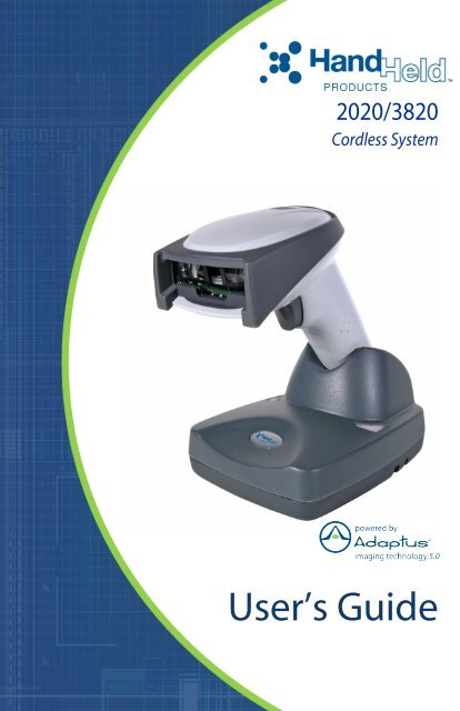
2020/<strong>3820</strong>Cordless SystemUser’s Guide
DisclaimerHand Held Products, Inc. (“Hand Held Products“) reserves the right to makechanges in specifications and other information contained in this documentwithout prior notice, and the reader should in all cases consult Hand HeldProducts to determine whether any such changes have been made. Theinformation in this publication does not represent a commitment on the part ofHand Held Products.Hand Held Products shall not be liable for technical or editorial errors oromissions contained herein; nor for incidental or consequential damagesresulting from the furnishing, performance, or use of this material.This document contains proprietary information which is protected by copyright.All rights are reserved. No part of this document may be photocopied,reproduced, or translated into another language without the prior written consentof Hand Held Products.© 2004-2006 Hand Held Products, Inc. All rights reserved.Web Address: www.handheld.comMicrosoft® Pocket PC 2002, Windows®, Windows NT®, Windows 2000,Windows ME, Windows XP, ActiveSync®, Outlook®, and the Windows logo aretrademarks or registered trademarks of Microsoft Corporation.The Bluetooth® word mark and logos are owned by Bluetooth SIG, Inc.
Statement of Agency ComplianceThe 2020-5B/<strong>3820</strong> system meets or exceeds the requirements of all applicablestandards organizations for safe operation. However, as with any electricalequipment, the best way to ensure safe operation is to operate them accordingto the agency guidelines that follow. Please read these guidelines carefullybefore using your 2020-5B/<strong>3820</strong> system.Regulatory and Safety Approvals for the 2020-5B/<strong>3820</strong>ParameterUSACanadaEuropean CommunitySpecificationFCC Part 15, Class BICES-003EN 55022 (CISPR 22) Class BEN60950EN60825-1EN55024:1998FCC Class B Compliance StatementThis device complies with part 15 of the FCC Rules. Operation is subject to thefollowing two conditions:1. This device may not cause harmful interference.2. This device must accept any interference received, including interferencethat may cause undesired operation.This equipment has been tested and found to comply with the limits for a ClassB digital device pursuant to part 15 of the FCC Rules. These limits are designedto provide reasonable protection against harmful interference in a residentialinstallation. This equipment generates, uses, and can radiate radio frequencyenergy and, if not installed and used in accordance with the instructions, maycause harmful interference to radio communications. If this equipment doescause harmful interference to radio or television reception, which can bedetermined by turning the equipment off and on, the user is encouraged to try tocorrect the interference by one or more of the following measures:• Reorient or relocate the receiving antenna.• Increase the separation between the equipment and receiver.• Connect the equipment into an outlet on a circuit different from that to whichthe receiver is connected.• Consult the dealer or an experienced radio or television technician for help.
If necessary, the user should consult the dealer or an experienced radio/television technician for additional suggestions. The user may find the following<strong>book</strong>let helpful: “Something About Interference.” This is available at FCC localregional offices. Hand Held Products, Inc. is not responsible for any radio ortelevision interference caused by unauthorized modifications of this equipmentor the substitution or attachment of connecting cables and equipment other thanthose specified by Hand Held Products, Inc. The correction is the responsibilityof the user. Use only shielded data cables with this system.In accordance with FCC 15.21, changes or modifications not expresslyapproved by the party responsible for compliance could void the user’s authorityto operate the equipment.This device and its antenna must not be co-located or operatingin conjunction with any other antenna or transmitter. To maintain! compliance with FCC RF exposure guidelines for body-wornoperation, do not use accessories that contain metalliccomponents and ensure that the device is at least 15mm (0.6inches) from the body.Canadian ComplianceThis Class B digital apparatus compiles with Canadian ICES-003. Operation issubject to the following two conditions:1. This device may not cause harmful interference.2. This device must accept any interference received, including interferencethat may cause undesired operation.3. To prevent radio interference to the licensed service, this device is intendedto be operated indoors and away from windows to provide maximumshielding. Equipment (or its transmit antenna) that is installed outdoors issubject to licensing.Cet appareil numérique de la Classe B est conforme à la norme NMB-003 duCanada.CE ComplianceThe CE mark on the product indicates that the system has been testedto and conforms with the provisions noted within the 89/336/EECElectromagnetic Compatibility Directive and the 73/23/EEC Low VoltageDirective.For CE-related inquiries, please contact:Hand Held ProductsNijverheidsweg 9-135627 BT EindhovenThe Netherlands
Hand Held Products shall not be liable for use of our product with equipment(i.e., power supplies, personal computers, etc.) that is not CE marked and doesnot comply with the Low Voltage Directive.Regulatory Approvals for Bluetooth Radio DevicesRF devices are designed to comply with the most current applicable standardson safe levels of RF energy developed by the Institute of Electrical andElectronics Engineers (IEEE) and the American National Standards Institute(ANSI) and have been recommended for adoption by the FederalCommunications Commission (FCC).ParameterSpecificationRF ApprovalsU.S.A. FCC Part 15.247Canada RSS 210Bluetooth Radio Device R&TTE Compliance StatementThese devices are in conformity with all essential requirements of the R&TTEDirective (1999/5/EC). This equipment has been assessed to the followingstandards:ParameterSpecificationR&TTE EN 300 328-2:2000EN 301 489-1 (2002-08)EN 301 489-17 (2002-08)EN 60950:2000EN 50361:2001This product is marked within accordance with the productrequirements specified in the R&TTE Directive, 1999/5/EC.The equipment is intended for use throughout the European Community.Bluetooth Qualified ProductBluetooth Qualified Body approved as a Bluetooth Class II radio.
UL and cUL StatementUL listed UL1950 and CSA 22.2 No.950. cUL listed UL1950 and CSA 22.2 No950.TÜV StatementTÜV or GS marked to EN60950 and EN60825-1.C-Tick StatementConforms to AS/NZS 3548. C-Tick number: N10410.MexicoCertifiedPatentsPlease refer to the <strong>3820</strong> packaging for patent information.Solids and Water ProtectionThe <strong>3820</strong> has a rating of IP41, immunity of foreign particles and dripping water.
Required Safety Labels<strong>3820</strong><strong>3820</strong>SR0C0BE
B2020-5B''US and Foreign Patents PendingFCC <strong>ID</strong>:CanadaHD5MX2702BIC1693BMX2702BHand Held Products, Inc.Skaneateles Falls, NY 13153www.handheld.comI.T.E.ACCESSORY7D21E1537400682"Made in China"
Table of ContentsChapter 1 - Getting StartedAbout This Manual............................................................... 1-1Unpacking the System .......................................................... 1-2Models .................................................................................. 1-2Cordless System: Main Components.................................... 1-3About the Battery.................................................................. 1-3Proper Disposal of the Battery ....................................... 1-4Base Charge Mode................................................................ 1-5Linking Scanner to Base....................................................... 1-6Scanner Modes...................................................................... 1-6Unlinking the Scanner.................................................... 1-6Single Scanner Operation ..................................................... 1-7Locked Link Mode - Single Scanner ............................. 1-7Open Link Mode - Single Scanner................................. 1-7Override Locked Scanner............................................... 1-7Multiple Scanner Operation.................................................. 1-8Scanner Name....................................................................... 1-8Changing Scanner Name - Serially................................ 1-8Changing Scanner Name - via Bar Codes...................... 1-9Scanner Report.................................................................... 1-10Application Work Groups................................................... 1-10Application Work Group Selection.............................. 1-11Resetting the Standard Product Default Settings:Current Application Work Group .................................... 1-12Resetting the Standard Product Default Settings: AllApplication Work Groups................................................ 1-12Using the Scanner with Bluetooth Devices ........................ 1-13Changing Bluetooth PIN Code..................................... 1-13Out-of-Range Alarm........................................................... 1-13Duration........................................................................ 1-13Alarm Sound Type ....................................................... 1-14Data Accumulation Mode................................................... 1-14Beeper and LED Sequences and Their Meaning................ 1-14<strong>3820</strong> LED Sequences and Their Meaning ................... 1-152020-5B LED Sequences and Their Meaning ............. 1-15i
Basic Operation of the Cordless System ............................ 1-16System Conditions ....................................................... 1-17Communication Between the Cordless System and the Host1-18Connecting the Base When Powered by Host(Keyboard Wedge)........................................................... 1-18Reading Techniques............................................................ 1-20Resetting the Standard Product Defaults ............................ 1-20Plug and Play ...................................................................... 1-20Keyboard Wedge Connection............................................. 1-21Laptop Direct Connect ................................................. 1-21RS-232.......................................................................... 1-21Wand Emulation Plug & Play...................................... 1-22IBM 4683 Ports 5B, 9B, and 17 Interface .......................... 1-23Connecting the Base with USB .......................................... 1-24IBM SurePos ............................................................... 1-25USB PC or Macintosh Keyboard ................................. 1-25USB H<strong>ID</strong>...................................................................... 1-26USB Com Port Emulation............................................ 1-26Connecting the Base with Serial Wedge ............................ 1-27Chapter 2 - Terminal InterfacesTerminal <strong>ID</strong> .......................................................................... 2-1Supported Terminals............................................................. 2-2Keyboard Country ................................................................ 2-4Keyboard Style ..................................................................... 2-6Keyboard Modifiers.............................................................. 2-7Connecting the Base with RS-232 Serial Port...................... 2-8RS-232 Baud Rate.......................................................... 2-9RS-232 Word Length: Data Bits, Stop Bits, and Parity2-10RS-232 Handshaking ................................................... 2-11Host ACK Selection..................................................... 2-11Host ACK Enable......................................................... 2-12ii
Wand Emulation ................................................................. 2-14Wand Emulation Connection ....................................... 2-14Wand Emulation Transmission Rate............................ 2-15Wand Emulation Polarity ............................................. 2-15Wand Emulation Idle.................................................... 2-16Wand Emulation Data Block Size................................ 2-16Wand Emulation Delay Between Blocks ..................... 2-16Wand Emulation Overall Checksum............................ 2-17Chapter 3 - OutputGood Read Indicators ........................................................... 3-1Beeper – Good Read....................................................... 3-1Beeper Volume – Good Read......................................... 3-1Beeper Pitch – Good Read ............................................. 3-2Beeper Duration – Good Read ....................................... 3-2LED – Good Read .......................................................... 3-2Number of Beeps – Good Read...................................... 3-3Good Read Delay.................................................................. 3-3User-Specified Good Read Delay .................................. 3-3Scanner Trigger Modes......................................................... 3-4Manual/Serial Trigger, Low Power................................ 3-4Automatic Trigger .......................................................... 3-5Presentation Mode.......................................................... 3-5Hands Free Time-Out ........................................................... 3-6Reread Delay......................................................................... 3-6User-Specified Reread Delay ......................................... 3-6Centering Window................................................................ 3-7Output Sequence Overview .................................................. 3-8Output Sequence Editor.................................................. 3-9Require Output Sequence............................................... 3-9Multiple Symbols................................................................ 3-12No Read .............................................................................. 3-12Video Reverse..................................................................... 3-12iii
Chapter 4 - Data EditingPrefix/Suffix Overview......................................................... 4-1To Add a Prefix or Suffix: ............................................ 4-2To Clear One or All Prefixes or Suffixes:...................... 4-3To Add a Carriage Return Suffix to all Symbologies.... 4-3Prefix Selections............................................................. 4-3Suffix Selections ............................................................ 4-4Function Code Transmit................................................. 4-4Intercharacter, Interfunction, and Intermessage Delays ....... 4-4Intercharacter Delay....................................................... 4-5User Specified Intercharacter Delay .............................. 4-5Interfunction Delay ........................................................ 4-6Intermessage Delay ........................................................ 4-6Chapter 5 - Data FormattingData Format Editor Introduction .......................................... 5-1To Add a Data Format.................................................... 5-1Other Programming Selections ...................................... 5-2Data Format Editor Commands ..................................... 5-2Data Format Editor......................................................... 5-4Data Formatter ............................................................... 5-5Alternate Data Formats .................................................. 5-5Chapter 6 - SymbologiesIntroduction........................................................................... 6-1All Symbologies ................................................................... 6-1Message Length.................................................................... 6-2Codabar................................................................................. 6-3Codabar Start/Stop Characters ...................................... 6-3Codabar Check Character .............................................. 6-3Codabar Concatenation .................................................. 6-4Codabar Message Length............................................... 6-5iv
Code 39 ................................................................................. 6-5Code 39 Start/Stop Characters....................................... 6-5Code 39 Check Character............................................... 6-6Code 39 Message Length ............................................... 6-6Code 39 Append............................................................. 6-7Code 32 Pharmaceutical (PARAF) ................................ 6-7Full ASCII ...................................................................... 6-8Code 39 Code Page ........................................................ 6-9Interleaved 2 of 5 .................................................................. 6-9Check Digit..................................................................... 6-9Interleaved 2 of 5 Message Length .............................. 6-10Code 93 ............................................................................... 6-11Code 93 Message Length ............................................. 6-11Code 93 Code Page ...................................................... 6-11Straight 2 of 5 Industrial ..................................................... 6-12Straight 2 of 5 Industrial Message Length ................... 6-12Straight 2 of 5 IATA Message Length ......................... 6-13Matrix 2 of 5 ....................................................................... 6-13Matrix 2 of 5 Message Length ..................................... 6-14Code 11 ............................................................................... 6-14Check Digits Required ................................................. 6-14Code 11 Message Length ............................................. 6-15Code 128 ............................................................................. 6-15ISBT 128 Concatenation .............................................. 6-16Code 128 Message Length ........................................... 6-16Code 128 Code Page .................................................... 6-16Code 128 Function Code Transmit .............................. 6-17Telepen................................................................................ 6-17Telepen Output............................................................. 6-17Telepen Message Length.............................................. 6-18UPC A................................................................................. 6-18UPC A Check Digit...................................................... 6-18UPC A Number System ............................................... 6-19UPC A Addenda........................................................... 6-19UPC A Addenda Required ........................................... 6-19UPC A Addenda Separator........................................... 6-20UPC-A/EAN-13 with Extended Coupon Code................... 6-20v
viUPC E0 and UPC E1 .......................................................... 6-21UPC E0 and UPC E1 Expand ...................................... 6-21UPC E0 and UPC E1 Addenda Required .................... 6-21UPC E0 and UPC E1 Addenda Separator.................... 6-22UPC E0 Check Digit .................................................... 6-22UPC E0 Number System.............................................. 6-22UPC E0 Addenda ......................................................... 6-23EAN/JAN 13....................................................................... 6-23EAN/JAN 13 Check Digit............................................ 6-23EAN/JAN 13 Addenda................................................. 6-24EAN/JAN 13 Addenda Required................................. 6-24EAN/JAN 13 Addenda Separator ................................ 6-24ISBN Translate............................................................. 6-25EAN/JAN 8......................................................................... 6-25EAN/JAN 8 Check Digit.............................................. 6-25EAN/JAN 8 Addenda................................................... 6-26EAN/JAN 8 Addenda Required................................... 6-26EAN/JAN 8 Addenda Separator .................................. 6-26MSI ..................................................................................... 6-27MSI Check Character................................................... 6-27MSI Message Length ................................................... 6-28Plessey Code....................................................................... 6-28Plessey Message Length .............................................. 6-28RSS Limited ....................................................................... 6-29RSS Expanded .................................................................... 6-30RSS Expanded Message Length .................................. 6-30EAN•UCC Emulation......................................................... 6-30China Post Code ................................................................. 6-31Korea Post Code ................................................................. 6-32Korea Post Message Length......................................... 6-32PosiCode A and B............................................................... 6-33PosiCode Message Length ........................................... 6-33Codablock F........................................................................ 6-34Codablock F Message Length...................................... 6-34Code 16K............................................................................ 6-35Code 16K Message Length .......................................... 6-35
Code 49 ............................................................................... 6-36Code 49 Message Length ............................................. 6-36Chapter 7 - Interface KeysKeyboard Function Relationships......................................... 7-1Supported Interface Keys...................................................... 7-3Chapter 8 - UtilitiesTo Add a Test Code I.D. Prefix to All Symbologies ............ 8-1Reset Scanner........................................................................ 8-1Show Software Revision....................................................... 8-1Show Data Format ................................................................ 8-1Scanner Report...................................................................... 8-2Scanner Address.................................................................... 8-2Base Address......................................................................... 8-2Resetting the Standard Product Default Settings:Current Application Work Group....................................... 8-2Resetting the Standard Product Default Settings: AllApplication Work Groups .................................................. 8-3Temporary Visual Xpress Configuration.............................. 8-3Chapter 9 - Visual XpressVisual Xpress Introduction ................................................... 9-1Installing Visual Xpress from the Web .......................... 9-2Chapter 10 - Serial Programming CommandsConventions ........................................................................ 10-1Menu Command Syntax ..................................................... 10-1Query Commands......................................................... 10-2Concatenation of Multiple Commands......................... 10-3Responses ..................................................................... 10-3Examples of Query Commands.................................... 10-3Trigger Commands ............................................................. 10-4Resetting the Standard Product Default Settings:Current Application Work Group..................................... 10-5vii
Resetting the Standard Product Default Settings: AllApplication Work Groups................................................ 10-5Menu Commands................................................................ 10-6Terminal Interfaces ............................................... 10-7Output Selections ................................................ 10-10Prefix/Suffix Selections ...................................... 10-12Data Formatter Selections .................................. 10-13Symbologies ....................................................... 10-13Chapter 11 - Product Specifications<strong>3820</strong> Product Specifications ............................................... 11-12020-5B Product Specifications ......................................... 11-2<strong>3820</strong> Depth of Field............................................................ 11-3Chapter 12 - MaintenanceMaintenance........................................................................ 12-1Cleaning the Scanner’s Window.................................. 12-1Inspecting Cords and Connectors................................. 12-1Replacing the 2020-5B Interface Cable:...................... 12-2Troubleshooting Base ......................................................... 12-2Chapter 13 - Customer SupportAppendix AProduct Service and Repair ................................................ 13-1Online Product Service and Repair Assistance............ 13-2Technical Assistance .......................................................... 13-2Online Technical Assistance........................................ 13-3Limited Warranty................................................................ 13-3Symbology Chart..................................................................A-1ASCII Conversion Chart (Code Page 1252).........................A-2Code Page Mapping of Printed Bar Codes...........................A-4viii
1Getting StartedThe <strong>3820</strong> cordless scanning system consists of one 2020-5B base and one <strong>3820</strong>Cordless Linear Scanner. Up to seven scanners may be linked to one base. The<strong>3820</strong> marks a new performance level for hand held scanners. The <strong>3820</strong> ispowered by Hand Held Products Adaptus TM Imaging Technology 5.0. Theperformance of Adaptus technology delivers aggressive read rates and depthsof field on 1D codes.Designed for today’s demanding retail and commercial environments, the <strong>3820</strong>offers a superior reading range, durability, and the ability to read poor quality barcodes. Linear imaging technology is defined by a bright and sharply focusedaiming line, high resolution imaging, and fast reading speed. The <strong>3820</strong> iscomfortable to hold, easy to use, rugged, and excellent for retail applications, aswell as for all general scanning applications.The cordless system is an economical, durable solution for a wide variety ofportable data collection applications. The cordless system features:• a tough, ergonomic thermoplastic housing for comfort and durability.• an advanced two-way spread-spectrum radio, Bluetooth ® wirelesstechnology• a wide range of interfaces: keyboard wedge, wand emulation, RS-232terminals, USB, and legacy decoders.• visible and audible feedback for confirmation of a successful decode.• a rechargeable battery designed to operate through a whole work day.The cordless system can be programmed for many communication parametersand input/output protocols compatible to the host, as well as advanced dataediting and formatting.About This ManualThis manual contains information to help you set up, operate, and program thecordless system. Product specifications, connector pinouts, a troubleshootingguide, and customer support information are also provided.Hand Held Products bar code scanners are factory programmed for the mostcommon terminal and communications settings. If you need to change thesesettings, programming is accomplished by scanning the bar codes in this guide.An asterisk (*) next to an option indicates the default setting.This section contains the following information:• Unpacking the System• Cordless System Main Components• Battery and Charging Information• Linking the Scanner to the Base• Beeper and LED Sequences and Their Meaning• Basic Operation of the Cordless System2020/<strong>3820</strong> User’s Guide 1 - 1
• Communication Between the Cordless System and the Host• Connection of the Base to an InterfaceUnpacking the SystemAfter you open the shipping carton containing the product, take the followingsteps:• Check to make sure everything you ordered is present.• Save the shipping container for later storage or shipping.• Check for damage during shipment. Report damage immediately to thecarrier who delivered the carton.ModelsModelsDescription2020-5BE Base: Keyboard wedge, TTL level 232, TTL level 232serial wedge, IBM 4683, wand emulation, USB keyboard,USB H<strong>ID</strong>, USB retail (IBM SurePOS)<strong>3820</strong>SR0C0BE Cordless Linear Scanner1 - 2 2020/<strong>3820</strong> User’s Guide
Cordless System: Main ComponentsBattery Contained in HandleAbout the Battery!Use only the Li-ion battery packs provided by Hand Held Products. Theuse of any battery pack not sold by Hand Held Products will void yourwarranty and may result in damage to your unit.Power is supplied to the cordless scanner by a rechargeable battery that isintegrated in the scanner handle. Each scanner is shipped with a battery. (SeeProduct Specifications beginning on page 11-1.)Charging InformationThe battery is designed to charge while the scanner is positioned in the cordlessbase unit. Refer to "2020-5B LED Sequences and Their Meaning" on page 1-15for an interpretation of the Charge Status indicators.• Place the scanner in the base that is connected to an appropriate powersupply.2020/<strong>3820</strong> User’s Guide 1 - 3
Battery Recommendations• Batteries are shipped approximately 30% to 60% charged and should be fullycharged for maximum charge capacity.• The battery is a lithium ion cell and can be used without a full charge, as wellas can be charged without fully discharging, without impacting the battery life.There is no need to perform any charge/discharge conditioning on this celltype battery.• Do not disassemble the battery. There are no user-serviceable parts in thebattery.• Keep the base connected to power when the host is not in use.• Replace a defective battery immediately since it could damage the <strong>3820</strong>.• Don’t short-circuit a battery or throw it into a fire. It can explode and causesevere personal injury.• Although your battery can be recharged many times, it will eventually bedepleted. Replace it after the battery is unable to hold an adequate charge.• If you are not sure if the battery or charger is working properly, send it to HandHeld Products or an authorized Hand Held Products service center forinspection.Proper Disposal of the BatteryWhen the battery has reached the end of its useful life, thebattery should be disposed of by a qualified recycler orhazardous materials handler. Do not incinerate the battery ordispose of the battery with general waste materials. You maysend batteries to Hand Held Products (postage paid). Theshipper is responsible for complying with all federal, state, andlocal laws and regulations related to the packing, labeling,manifesting, and shipping of spent batteries. Contact theProduct Service Department (see 13-1) for recycling or disposal information.Since you may find that your cost of returning the batteries significant, it may bemore cost effective to locate a local recycle/disposal company.1 - 4 2020/<strong>3820</strong> User’s Guide
Base Charge ModeIn order for the battery to be charged, there must be enough voltage for thecircuitry to work. There are three conditions during which power can be suppliedto the base:Condition 1: 9VDC power supply connected to the barrel connectorCondition 2: 12VDC host power source onlyCondition 3: 5VDC host power source onlyThe chart below describes each selection by condition.Condition 1 Condition 2 Condition 3Automatic Fast Charge Slow Charge No ChargeFull Charge Rate Fast Charge Fast Charge No ChargeLow Charge Rate Slow Charge Slow Charge No ChargeBattery Charge Off No Charge No Charge No ChargeUsing a slow charge rate draws less current (power) from the input power sourcewhen the battery is mostly discharged.Scan the appropriate bar code for your application. Default = Automatic.* AutomaticFull Charge RateLow Charge RateBattery Charge Off2020/<strong>3820</strong> User’s Guide 1 - 5
Linking Scanner to BaseWhen newly shipped or defaulted to factory settings, the base and scanner arenot linked. Once the scanner is placed into the base, the software automaticallylinks the scanner and the base. If the scanner and base have previously beenlinked, you do not receive any feedback. If this is the first time that the scannerand base are linked, both devices emit a short chirp when their radios link. Atthis point, you are set to one scanner to one base.<strong>3820</strong> ScannerGreen LEDRed LED2020-5B Cordless Base1. Provide power to the base.2. Place the <strong>3820</strong> into the base. The scanner and base link.3. To determine if your cordless system is set up correctly, scan one of thesample bar codes in the back of this manual. If the scanner provides asingle good read beep and the green LED lights, the scanner hassuccessfully linked to the base. If you receive a triple error beep and the redLED lights, the scanner has not linked to the base.Scanner ModesThe <strong>3820</strong> is capable of working in single scanner mode, multiple scanner mode,or with Blutetooth devices, other than the 2020-5B base.Unlinking the ScannerIf the base has a scanner linked to it, that scanner must be unlinked before a newscanner can be linked. Once the previous scanner is unlinked, it will no longercommunicate with the base. To unlink a scanner from the base, scan the UnlinkScanner bar code below.Unlink Scanner1 - 6 2020/<strong>3820</strong> User’s Guide
Single Scanner OperationThere are two link modes to accommodate different applications: Locked LinkMode and Open Link Mode. Scan the appropriate bar codes included in theOpen Link and Locked Link Mode explanations that follow to switch from onemode to another. Default = Locked Link Mode.Locked Link Mode - Single ScannerIf you link a scanner to a base using the Locked Link Mode, other scanners areblocked from being linked if they are inadvertently placed into the base. If youdo place a different scanner into the base, it will charge the scanner, but thescanner will not be linked.* Locked Link Mode(Single Scanner)To use a different scanner, you need to unlink the original scanner by scanningthe Unlink Scanner bar code. (See "Scanner Modes" on page 1-6.)Open Link Mode - Single ScannerWhen newly shipped or defaulted to factory settings, the base and scanner arenot linked. By placing a scanner into the base, they establish a link. Placing adifferent scanner into the base establishes a new link and the old scanner isunlinked. Each time a scanner is placed into the base, it becomes the linkedscanner; the old scanner is unlinked.Open Link Mode(Single Scanner)Override Locked ScannerIf you need to replace a broken or lost scanner that is linked to a base, scan theOverride Locked Scanner bar code below with a new scanner and place thatscanner in the base. The locked link will be overridden; the broken or lostscanner’s link with the base will be removed, and the new scanner will be linked.Override Locked Scanner(Single Scanner)2020/<strong>3820</strong> User’s Guide 1 - 7
Multiple Scanner OperationTo put the scanner in multiple scanner mode, scan the bar code below. Onceyou scan this bar code, the scanner is unlinked from the base and must beplaced into the base to re-link.Note: Multiple Scanner Operation Mode allows you to link up to 7 scanners toone base. You cannot join an eighth scanner until you unlink one of the7 scanners or take a scanner out of range.Scanner NameMultiple Scanner OperationYou are able to assign a name to each scanner you are using. It will be helpfulto name the scanners if you have multiple scanners linked to one base so thatyou will be able to control the scanner receiving imaging commands sent fromthe base. The default name for an <strong>3820</strong> is “<strong>3820</strong>”. If you have more than one<strong>3820</strong> linked to a base, the first scanner that is linked to the base receivescommands addressed using this name.Changing Scanner Name - SeriallyIf you wish to change the name, you may change it via a serial command (referto "Menu Command Syntax" on page 10-1) or via a bar code command. Tochange the name serially, unlink all except one of the <strong>3820</strong>s from the base. Send“:<strong>3820</strong>:BT_NAMname.”, where name is the new scanner name. If you wish tochange the name of additional <strong>3820</strong>s, re-link them one at a time and repeat the“:<strong>3820</strong>:BT_NAMname.” command for each scanner.1 - 8 2020/<strong>3820</strong> User’s Guide
Changing Scanner Name - via Bar CodesIf you wanted to set up your scanners with names 0001-0007, you may scan thebar codes below. Scan the Reset bar code after each name change and wait forthe scanner to re-link to the base before scanning the next bar code to name thenext scanner.0001000200030004000500060007ResetAlternatively, you may change the name with a bar code command if you cannotsend serial commands to the base. One way to do this is to scan the bar codebelow and scan a number for the scanner name. For example, if you had 7scanners to one base, scan the bar code below with the first scanner, scan the1 bar code on the Programming Chart inside the back cover of this manual andscan Save. Then scan the Reset bar code and wait for the scanner to re-link tothe base before scanning the next bar code. Repeat that process for scannernumber 2, 3, 4 etc.Scanner NameIf you want to assign an alphabetic name to the scanner, create a Code 128 barcode containing “~BT_NAMname.” followed by a FNC3 character (hexidecimal83), where name is the new scanner name. Scan the Reset bar code (page 1-9or on the Programming Chart inside the back cover of this manual). You mayuse Barcode Builder, which is included with Quick*View. You may downloadQuick*View from the Hand Held Products website: www.handheld.com.2020/<strong>3820</strong> User’s Guide 1 - 9
Scanner ReportScan the bar code below to generate a report for the connected scanners. Thereport indicates the port, work group, scanner name, and address.Scanner ReportApplication Work GroupsYour cordless system can have up to seven scanners linked to one base. Youcan also have up to seven work groups. If you want to have all of the scanners’settings programmed alike, you don’t need to use more than one work group. Ifyou want each scanner to have unique settings (e.g., beeper volume, prefix/suffix, data formatter), then you may program each scanner to its own uniquework group and may program each scanner independently. Visual XPress(page 9-1) makes it easy for you to program your system for use with multiplescanners and multiple work groups.The scanner keeps a copy of the menu settings it is using. Whenever thescanner is connected or reconnected to a base, the scanner is updated with thelatest settings from the base for its work group. The scanner also receives menusetting changes processed by the base. If a scanner is removed from one baseand placed into another base, it will be updated with the new base settings forwhatever work group that the scanner was previously assigned. For example, ifthe scanner was in work group 1 linked to the first base, it will be placed in workgroup 1 in the second base with the associated settings.1 - 10 2020/<strong>3820</strong> User’s Guide
Application Work Group SelectionThis programming selection allows you to assign a scanner to a work group byscanning the bar code below. You may then program the settings (e.g., beepervolume, prefix/suffix, data formatter) that your application requires.* Group 0Group 1Group 2Group 3Group 4Group 5Group 62020/<strong>3820</strong> User’s Guide 1 - 11
Resetting the Standard Product Default Settings:Current Application Work GroupIf you aren’t sure what programming options are in your scanner, or you’vechanged some options and want the standard product default settings restored,scan the Standard Product Default Settings: Current Application Group barcode below.The Menu Commands starting on page 10-6 list the factory default settings foreach of the commands (indicated by an asterisk (*) on the programming pages).Note: Scanning this bar code also causes both the scanner and the base toperform a reset and become unlinked. Refer to "Linking Scanner toBase" on page 1-6 for additional information.Standard Product Default Settings:Current Application GroupNote: If your scanner is in multiple scanner mode and you scan either thecurrent or all application group default bar code, you will hear up to 30seconds of beeping while all scanners are re-linked from the base and thesettings are defaulted to * settings. The default interface is keyboardwedge and the default scanner mode is single scanner locked link mode.Resetting the Standard Product Default Settings: AllApplication Work GroupsThe following bar code defaults all of the work groups to the factory settings.Standard Product Default Settings:All Application GroupsThe Menu Commands starting on page 10-6 list the standard product defaultsettings for each of the commands (indicated by an asterisk (*) on theprogramming pages).1 - 12 2020/<strong>3820</strong> User’s Guide
Using the Scanner with Bluetooth DevicesThe <strong>3820</strong> scanner may be used either with the 2020-5B base or with otherBluetooth devices. Scanning the Non-Base Bluetooth Connection bar codebelow allows the scanner to be used with other Bluetooth devices (e.g., PDA, PC- Bluetooth USB Adapter). After you scan the bar code below, follow theinstructions supplied with your Bluetooth device to locate the scanner andconnect to it. If you go out of range with your scanner, the scanner automaticallyreconnects to the Bluetooth device. If you want to relink to the 2020-5B base,refer to "Single Scanner Operation" on page 1-7 or "Multiple ScannerOperation" on page 1-8.Note: The multiple work groups option is not available when you are using theimager with Bluetooth devices other than the 2020-5B base.Non-Base BT ConnectionChanging Bluetooth PIN CodeSome devices require a PIN code as part of the Bluetooth security features. Yourscanner’s default PIN is 1234, which you may need to enter the first time youconnect to your PDA or PC. The PIN code must be between 1 and 16 characters.To change the PIN, scan the bar code below and then scan the appropriatenumeric bar codes from the Programming Chart inside the back cover of thismanual. Scan Save to save your selection.Bluetooth PINOut-of-Range AlarmDurationIf your scanner is out range of the base, an alarm sounds from both your baseand scanner. To activate the alarm options for the scanner or the base and toset the alarm duration, scan the appropriate bar code below and then set thetime-out duration (from 0-3000 seconds) by scanning digits on the ProgrammingChart inside the back cover, then scanning Save. Default = 0 sec (no alarm).Base Alarm DurationScanner Alarm Duration2020/<strong>3820</strong> User’s Guide 1 - 13
Note: If you are out of range when you scan a bar code, you will receive an errorbeep even if you do not have the alarm set. You receive the error beepsince the data could not be communicated to the base or the host.Alarm Sound TypeIf you have set the out-of-range alarm enabled, you may change the alarm typefor the scanner or base by scanning the appropriate bar code below and thenscanning a digit (0-7) bar code and the Save bar code on the Programming Chartinside the back cover of this manual. Default = 0. Set the sound type to fit yourapplication.Base Alarm TypeScanner Alarm TypeData Accumulation ModeScan the bar codes below to turn data accumulation (batch) mode on and off. Ifdata accumulation mode is on, bar code data is stored when the scanner is outof range of the base and transmitted once the scanner is back in range.Data Accumulation Mode On* Data Accumulation Mode OffBeeper and LED Sequences and Their MeaningThe <strong>3820</strong> contains LEDs on the top of the unit to indicate its power up,communication, and battery status. Simply stated, red LED = error; greenLED = success of any type. The unit’s audible indicators have meaning as well:3 beeps = error; 2 beeps = menu change; 1 beep = all other successes.The table below lists the indication and cause of the LED illumination and beepsfor the <strong>3820</strong>.1 - 14 2020/<strong>3820</strong> User’s Guide
<strong>3820</strong> LED Sequences and Their MeaningLED Indication Beeper Indication CauseNormal OperationRed Flash None Battery lowGreen Flash1 beepSuccessful communicationor linkingRed, blinking 3 beeps Failed communicationMenu OperationGreen Flash 2 beeps Successful menu changeRed, blinking 3 beeps Unsuccessful menu change2020-5B LED Sequences and Their MeaningThe base contains a red LED that indicates the status of the unit and verifies itscommunication with the host system and a green LED that indicates scannerbattery charge condition.The tables below list the indication and cause of the LED illumination and beepsfor the 2020-5B.System ConditionPower On/System IdlePower On/Diagnostic ErrorReceiving Data (2020-5B only)Base requests status from itsown Bluetooth radioSystem Status Indicator (Red LED)LED is onBlink LED for long duration, pulsing indefinitelyBlink LED for short duration in multiple pulses. Occurswhile transferring data to/from the RF module or the Hostport.Blink LED once (occurs approx. every 30 seconds)2020/<strong>3820</strong> User’s Guide 1 - 15
Note: Charging only occurs with external power applied to the 2020-5B or 12volt Host power.Charge ConditionCharge Status Indicator (Green LED)Scanner inserted into base Three flashes>80% charged On continuously30% to 80% charged Slow flash, 1 second on, 1 second off
Cordless ScannerThe cordless scanner enables fast and accurate bar code scanning using a noncontactlinear scanner.The scanner is comprised of a linear scanner, a decode/control assembly, andan RF communication module. The scan engine performs the bar code imageillumination and sensing. The decode/control assembly coordinates the centralcommunication activities including: capturing and decoding the bar code imagedata, performing software activities (parameter menuing, visual indicatorsupport, low battery indication), and data translation required for the host system.The RF communication module performs the data exchange between thescanner and the base.System ConditionsThe components of the cordless system interact in specific ways as youassociate a scanner to a base, as you move a scanner out of range, bring ascanner back in range, or swap scanners between two cordless systems. Thefollowing information explains the cordless system operating conditions.Linking ProcessOnce a scanner is placed into the base, the scanner’s battery charge status ischecked, and software automatically detects the scanner and links it to the basedepending on the selected link mode.Scanner Is Out of RangeThe cordless scanner is in communication with its base, even when it is nottransmitting bar code data. Whenever the scanner can’t communicate with thebase for a few seconds, it is out of range. If the scanner is out of range and youscan a bar code, the scanner issues a triple beep indicating no communicationwith the base. In addition, your scanner and base can sound an alarm ifprogrammed to emit an alarm. See Out-of-Range Alarm on page 1-13.Scanner Is Moved Back Into RangeThe scanner re-links if the scanner or the base have been reset or out of range.If the scanner re-links, you will hear a single chirp when the re-linking process(uploading of the parameter table) is complete.Out of Range and Back into Range with Data Accumulation ModeOnThe scanner may store a number of symbols (approximately 500 UPC symbols,others may vary) when out of range and then send them to the base when backin range. You will not hear a communication error beep in this mode, but you willhear a short buzz when you pull the trigger if the radio communication is notworking. Once the radio connection is made, the scanner produces a series ofbeeps while the data is being transferred to the base.2020/<strong>3820</strong> User’s Guide 1 - 17
Communication Between the Cordless System and the HostThe cordless scanner provides immediate feedback in the form of a “good read”indication (a green LED on the scanner and an audible beep) after a bar code isscanned correctly and the base has acknowledged receiving the data. This ispossible since the cordless system provides two-way communication betweenthe scanner and the base.When data is scanned, the data is sent to the host system via the base unit.Confirmation from the host system or the base indicates that the data sent wasreceived by the host. The cordless scanner recognizes data acknowledgement(ACK) from the base unit. If it cannot be determined that the data has beenproperly sent to the base, the scanner issues an error indication. You must thencheck to see if the scanned data was received by the host system.1) Good Read3) Base sendsdata to host2) ACK from baseConnecting the Base When Powered by Host(Keyboard Wedge)A base can be connected between the keyboard and PC as a “keyboard wedge,”plugged into the serial port, or connected to a portable data terminal in wandemulation or non decoded output mode. The following is an example of akeyboard wedge connection:1. Turn off power to the terminal/computer.1 - 18 2020/<strong>3820</strong> User’s Guide
2. Disconnect the keyboard cablefrom the back of the terminal/computer.Disconnect3. Connect theappropriateinterface cableto the base andto the terminal/computer andkeyboard.4. Turn theterminal/computer powerback on.1325. Program thebase for thekeyboard wedge interface. See "Keyboard Wedge Connection" on page 1-21.)6. Verify the base operation by scanning a bar code from the Sample Symbolsin the back of this manual.Note: Without using the 9-volt external, power supply, the base only usesenough power from the host to operate the interface. The scanner’sbattery is not charged when in this mode. Using the 9-volt, external powersupply allows the scanner’s battery to be charged, and no power is drawnfrom the host.2020/<strong>3820</strong> User’s Guide 1 - 19
Reading TechniquesThe scanner has a view finder that projects a bright red aiming beam thatcorresponds to its horizontal field of view. The aiming line should be centeredhorizontally over the bar code; it will not read if the aiming line is in any otherdirection.Good ReadBad ReadBad ReadThe best focus point for reading most code densities is about 5 inches (12.7 cm)from the unit. To read single or multiple symbols (on a page or on an object),hold the scanner at an appropriate distance from the target, pull the trigger, andcenter the aiming line on the symbol.Resetting the Standard Product DefaultsIf you aren’t sure what programming options are in your scanner, or you’vechanged some options and want the factory settings restored, scan theStandard Product Default Settings bar code below.The Menu Commands starting on page 10-6 lists the factory default settings foreach of the commands (indicated by an asterisk (*) on the programming pages).Note: Scanning this bar code also causes both the scanner and the base toperform a reset and become unlinked. Refer to "Linking Scanner toBase" on page 1-6 for additional information.Standard Product Default SettingsPlug and PlayPlug and Play bar codes provide instant scanner set up for commonly usedinterfaces.1 - 20 2020/<strong>3820</strong> User’s Guide
Note: After you scan one of the codes, power cycle the host terminal to have theinterface in effect.Keyboard Wedge ConnectionIf you want your system programmed for an IBM PC AT and compatibleskeyboard wedge interface with a USA keyboard, scan the bar code below.Keyboard wedge is the default interface.Note: The following bar code also programs a carriage return (CR) suffix.Laptop Direct ConnectIBM PC AT and Compatibleswith CR suffixFor most laptops, scanning the Laptop Direct Connect bar code allowsoperation of the scanner in parallel with the integral keyboard. The followingLaptop Direct Connect bar code selects terminal <strong>ID</strong> 03, programs a carriagereturn (CR) suffix and turns on Emulate External Keyboard (page 2-6).Laptop Direct Connectwith CR suffixRS-232The RS-232 Interface bar code is used when connecting to the serial port of aPC or terminal. The following RS-232 Interface bar code also programs acarriage return (CR) and a line feed (LF) suffix, baud rate, and data format asindicated below. It also changes the trigger mode to manual.OptionBaud RateData FormatSetting115,200 bps8 data bits, no parity bit, 1 stop bitRS-232 Interface2020/<strong>3820</strong> User’s Guide 1 - 21
Wand Emulation Plug & PlayIn Wand Emulation mode, the scanner decodes the bar code then sends data inthe same format as a wand scanner. The Code 39 Format converts allsymbologies to Code 39.The Same Code Format transmits UPC, EAN, Code 128 and Interleaved 2 of 5without any changes, but converts all other symbologies to Code 39.The Wand Emulation Plug & Play Code 39 Format bar code below sets theterminal <strong>ID</strong> to 61. The Wand Emulation Plug & Play Same Code Format barcode sets the terminal <strong>ID</strong> to 64. These Plug & Play bar codes also set theTransmission Rate to 25 inches per second, Output Polarity to black high, andIdle State to high. (If you want to change the terminal <strong>ID</strong> only, without changingany other scanner settings, please refer to Terminal <strong>ID</strong> on page 2-1.)Wand Emulation (Code 39 Format)Wand Emulation Same Code1 - 22 2020/<strong>3820</strong> User’s Guide
IBM 4683 Ports 5B, 9B, and 17 InterfaceScan one of the following “Plug and Play” codes to program the <strong>3820</strong> for IBM4683 Port 5B, 9B, or 17.Note: After scanning one of these codes, you must power cycle the cashregister.IBM 4683 Port 5B InterfaceIBM 4683 Port 9B HHBCR-1 InterfaceIBM 4683 Port 9B HHBCR-2 InterfaceIBM 4683 Port 17 InterfaceEach bar code above also programs the following suffixes for each symbology:Symbology SuffixEAN 80CEAN 13 16UPC A0DUPC E0ACode 3900 0A 0BInterleaved 2 of 5 00 0D 0BCode 128 * 00 0A 0BCode 128 ** 00 18 0B* Suffixes programmed for Code 128 with IBM 4683 Port 5B, IBM 4683 Port 9B HHBCR-1,and IBM 4683 Port 17 Interfaces**Suffixes programmed for Code 128 with IBM 4683 Port 9 HHBCR-2 Interface2020/<strong>3820</strong> User’s Guide 1 - 23
Connecting the Base with USBA base can be connected to the USB port of a computer.1. Connect the appropriate interface cable to the base and to the computer.2. Program the base for the USB interface by scanning the appropriateprogramming bar code.3. Verify the base operation by scanning a bar code from the Sample Symbolsin the back of this manual.For additional USB programming and technical information, refer to Hand HeldProducts “USB Application Note,” available at www.handheld.com.Note: Without using the 9-volt external, power supply, the base only usesenough power from the host to operate the interface. The scanner’sbattery is not charged when in this mode. Using the 9-volt, external powersupply allows the scanner’s battery to be charged, and no power is drawnfrom the host.1 - 24 2020/<strong>3820</strong> User’s Guide
IBM SurePosScan one of the following “Plug and Play” codes to program the <strong>3820</strong> for IBMSurePos (USB Hand Held scanner) or IBM SurePos (USB Tabletop scanner).Note: After scanning one of these codes, you must power cycle the cashregister.IBM SurePos (USB HandHeld Scanner) InterfaceIBM SurePos (USB TabletopScanner) InterfaceEach bar code above also programs the following suffixes for each symbology:Symbology SuffixEAN 80CEAN 13 16UPC A0DUPC E0ACode 3900 0A 0BInterleaved 2 of 5 00 0D 0BCode 12800 18 0BUSB PC or Macintosh KeyboardScan one of the following codes to program the <strong>3820</strong> for USB PC Keyboard orUSB Macintosh Keyboard. Scanning these codes adds a CR and LF, along withselecting the terminal <strong>ID</strong> (USB PC Keyboard - 124, USB Macintosh Keyboard -125, USB Japanese Keyboard (PC) - 134).USB Keyboard (PC)USB Japanese Keyboard (PC)USB Keyboard (Mac)2020/<strong>3820</strong> User’s Guide 1 - 25
USB H<strong>ID</strong>Scan the following code to program the <strong>3820</strong> for USB H<strong>ID</strong> bar code scanners.Scanning this code changes the terminal <strong>ID</strong> to 131.USB H<strong>ID</strong> Bar Code ScannerUSB Com Port EmulationScan the following code to program the <strong>3820</strong> to emulate a regular RS-232-basedCom Port. If you are using a Microsoft® Windows® PC, you will need todownload a driver from the Hand Held Products website (www.handheld.com).The driver will use the next available Com Port number. Apple® Macintoshcomputers recognize the scanner as a USB CDC class device and automaticallyuses a class driver. Scanning the code below changes the terminal <strong>ID</strong> to 130.Note: No extra configuration (e.g., baud rate) is necessary.CTS/RTS EmulationUSB Com Port EmulationUSB CTS/RTS Emulation On* USB CTS/RTS Emulation OffACK/NAK ModeACK/NAK On* ACK/NAK Off1 - 26 2020/<strong>3820</strong> User’s Guide
Connecting the Base with Serial WedgeThe 2020-5B uses TTL signal levels to wedge into an RS-232 serial network.Use only 2020-5B serial wedge cables to prevent damage to the base. Refer toConnecting the Base with RS-232 Serial Port on page 2-8 to set the baud rateand communications protocol.1. Turn off power to the computer.2. Disconnect the existing serial cable from the computer.3. Connect the appropriate interface cable to the base.Note: For the base to work properly, you must have the correct cable for yourtype of computer.Other device5464. Plug the serial connector into the serial port on your computer. Tighten thetwo screws to secure the connector to the port.5. Plug the other serial connector into the other device connection and tightenthe two screws.6. Plug the power supply barrel connector to the base, and plug the powersupply into the AC source.7. Once the base has been fully connected, power up the computer.2020/<strong>3820</strong> User’s Guide 1 - 27
To set up the serial wedge terminal <strong>ID</strong>, use the serial terminal <strong>ID</strong> 050 and followthe instructions on page 2-1. Make sure that all of the communicationparameters match on all of the connected devices. Choosing Both sendsscanned data to P1 and P2. Default = P1.* P1P2Both P1 and P21 - 28 2020/<strong>3820</strong> User’s Guide
2Terminal InterfacesTerminal <strong>ID</strong>If your interface is not a standard PC AT, refer to "Supported Terminals" on page2-2 through page 2-3, and locate the Terminal <strong>ID</strong> number for your PC. Scan theTerminal <strong>ID</strong> bar code below, then scan the numeric bar code(s) from theProgramming Chart inside the back cover of this manual to program the scannerfor your terminal <strong>ID</strong>. Scan Save to save your selection.For example, an IBM AT terminal has a Terminal <strong>ID</strong> of 003. You would scan theTerminal <strong>ID</strong> bar code, then 0, 0, 3 from the Programming Chart inside the backcover of this manual, then Save. If you make an error while scanning the digits(before scanning Save), scan the Discard code on the Programming Chart, scanthe Terminal <strong>ID</strong> bar code, scan the digits, and the Save code again.Note: The default interface for the 2020-5B is Keyboard Wedge (Term <strong>ID</strong> =003).Terminal <strong>ID</strong>SaveNote: After scanning one of these codes, you must power cycle your computer.2020/<strong>3820</strong> User’s Guide 2 - 1
Supported TerminalsTerminal Model(s) Terminal <strong>ID</strong>DEC VT510, 520, 525 (PC style) 005DECVT510, 520, 525 (DEC style 104LK411)Esprit 200, 400 005Heath Zenith PC, AT 003*HP Vectra 003*IBM XT 001IBM PS/2 25, 30, 77DX2 002IBM AT, PS/2 30–286, 50, 55SX, 60, 003*70, 70–061, 70–121, 80IBM 102 key 3151, 3161, 3162, 3163, 3191, 0063192, 3194, 3196, 3197, 3471,3472, 3476, 3477IBM 122 key 3191, 3192, 3471, 3472 007IBM 122 key 3196, 3197, 3476, 3477, 3486, 0083482, 3488IBM 122 key 3180 024IBM 122 key 3180 data entry keyboard 114IBM DOS/V 106 key PC & Workstation 102IBM SurePOS USB Hand Held Scanner 128**IBM SurePOS USB Tabletop Scanner 129**IBM Thinkpad 360 CSE, 340, 750 097IBM Thinkpad 106IBM Thinkpad 365, 755CV 003*I/O 122 key 2676D, 2677C, 2677D 008ITT 9271 007Lee Data IIS 007NEC 98XX Series 103Olivetti M19, M200 001Olivetti M240, M250, M290, M380, 003*P500RS-232 TTL 000Serial Wedge 050Silicon Graphics Indy, Indigoll 005Telex 88 key 078, 078A, 79, 80, 191, 196, 0251191,1192, 1471, 1472, 1476,1477, 1483Telex 88 key Data Entry Keyboard 112Telex 102 key 078, 078A, 79, 80, 191, 196,1191,1192, 1471, 1472, 1476,1477, 14830452 - 2 2020/<strong>3820</strong> User’s Guide
Supported Terminals (Continued)Terminal Model(s) Terminal <strong>ID</strong>Telex 122 key 078, 078A, 79, 80, 191, 196, 0461191,1192, 1471, 1472, 1476,1477, 1482, 1483USB PC Keyboard 124**USB Mac Keyboard 125**USB Com Port 130USB H<strong>ID</strong>POS 131**Wand Emulation (Code06139 Format)Wand Emulation (SameCode Format)064* Default for 2020-5B.**It is best to use the Plug and Play bar codes, beginning on page 1-25 to program theseinterfaces, rather than scanning the terminal <strong>ID</strong> listed in this table.2020/<strong>3820</strong> User’s Guide 2 - 3
Keyboard CountryScan the appropriate country code below to program the keyboard for yourcountry. As a general rule, the following characters are supported, but needspecial care for countries other than the United States:@ | $ # { } [ ] = / ‘ \ < > ~* United StatesBelgiumBrazilCanada (French)Czech RepublicDenmarkFinland (Sweden)FranceGermany/AustriaGreeceHungaryIsrael (Hebrew)2 - 4 2020/<strong>3820</strong> User’s Guide
Keyboard Country (continued)ItalyLatin AmericaNetherlands (Dutch)NorwayPolandPortugalRomaniaRussiaSCSSlovakiaSpainSwedenSwitzerland (German)Turkey FTurkey QU.K.2020/<strong>3820</strong> User’s Guide 2 - 5
Please refer to the Hand Held Products website (www.handheld.com) forcomplete keyboard country support information and applicable interfaces. If youneed to program a keyboard for a country other than one listed above, scan theProgram Keyboard Country bar code below, then scan the numeric barcode(s) for the appropriate country from the inside back cover, then the Save barcode.Program Keyboard CountryKeyboard StyleThis programs keyboard styles, such as Caps Lock and Shift Lock. Default =Regular.Regular is used when you normally have the Caps Lock key off.* RegularCaps Lock is used when you normally have the Caps Lock key on.Caps LockShift Lock is used when you normally have the Shift Lock key on (not commonto U.S. keyboards).Shift LockAutomatic Caps Lock is used if you change the Caps Lock key on and off. Thesoftware tracks and reflects if you have Caps Lock on or off (AT and PS/2 only).This selection can only be used with systems that have an LED which notes theCaps Lock status.Automatic Caps LockAutocaps via NumLock bar code should be scanned in countries (e.g.,Germany, France) where the Caps Lock key cannot be used to toggle CapsLock. The NumLock option works similarly to the regular Auotcaps, but uses theNumLock key to retrieve the current state of the Caps Lock.Autocaps via NumLock2 - 6 2020/<strong>3820</strong> User’s Guide
Emulate External Keyboard should be scanned if you do not have an externalkeyboard (IBM AT or equivalent).Note: After scanning the Emulate External Keyboard bar code, you must powercycle your computer.Keyboard ModifiersEmulate External KeyboardThis modifies special keyboard features, such as CTRL+ ASCII codes and TurboMode.Control + ASCII Mode On: The scanner sends key combinations for ASCIIcontrol characters for values 00-1F. Refer to Keyboard FunctionRelationships, page 7-1 for CTRL+ ASCII Values. Default = OffControl + ASCII Mode On* Control + ASCII Mode OffTurbo Mode: The scanner sends characters to a terminal faster. If the terminaldrops characters, do not use Turbo Mode. Default = OffTurbo Mode On* Turbo Mode OffNumeric Keypad Mode: Sends numeric characters as if entered from anumeric keypad. Default = OffNumeric Keypad Mode On* Numeric Keypad Mode Off2020/<strong>3820</strong> User’s Guide 2 - 7
Automatic Direct Connect Mode: This selection can be used if you have anIBM AT style terminal and the system is dropping characters. Default = OffAutomatic DirectConnect Mode OnConnecting the Base with RS-232 Serial Port1. Turn off power to the terminal/computer.2. Connect the appropriate interface cable to the base.* Automatic Direct ConnectMode OffNote: For the base to work properly, you must have the correct cable for yourtype of terminal/computer.42353. Plug the serial connector into the serial port on your computer. Tighten thetwo screws to secure the connector to the port.4. Plug the power supply barrel connector to the base, and plug the powersupply into the AC source.5. Once the base has been fully connected, power up the computer.2 - 8 2020/<strong>3820</strong> User’s Guide
All communication parameters between the scanner and terminal must match forcorrect data transfer through the serial port using RS-232 protocol. Scanning theRS-232 interface bar code, programs the scanner for an RS-232 interface at115,200 baud, parity–none, 8 data bits, 1 stop bit, and adds a suffix of a CR LF.RS-232 InterfaceRS-232 Baud RateBaud Rate sends the data from the scanner to the terminal at the specified rate.The host terminal must be set for the same baud rate as the scanner.Default = 115,200.3006001200240048009600192003840057,600* 115,2002020/<strong>3820</strong> User’s Guide 2 - 9
RS-232 Word Length: Data Bits, Stop Bits, and ParityData Bits sets the word length at 7 or 8 bits of data per character. If anapplication requires only ASCII Hex characters 0 through 7F decimal (text, digits,and punctuation), select 7 data bits. For applications which require use of the fullASCII set, select 8 data bits per character. Default = 8.Stop Bits sets the stop bits at 1 or 2. Default = 1.Parity provides a means of checking character bit patterns for validity.Default = None.7 Data, 1 Stop, Parity Even7 Data, 1 Stop, Parity None7 Data, 1 Stop, Parity Odd7 Data, 2 Stop, Parity Even7 Data, 2 Stop Parity None7 Data, 2 Stop, Parity Odd8 Data, 1 Stop, Parity Even* 8 Data, 1 Stop, Parity None8 Data, 1 Stop, Parity Odd2 - 10 2020/<strong>3820</strong> User’s Guide
RS-232 HandshakingRS-232 Handshaking allows control of data transmission from the scanner usingsoftware commands from the host device. CTS/RTS operates in mode 2. Whenthis feature is turned Off, no data flow control is used. When Data Flow Controlis turned On, the host device suspends transmission by sending the XOFFcharacter (DC3, hex 13) to the scanner. To resume transmission, the host sendsthe XON character (DC1, hex 11). Data transmission continues where it left offwhen XOFF was sent. Default = RTS/CTS, XON/XOFF and ACK/NAK Off.RTS/CTS On* RTS/CTS OffXON/XOFF On* XON/OFF OffACK/NAK On* ACK/NAK OffHost ACK SelectionSome applications require that the host terminal (or server) approve or rejectincoming bar code data and notify the operator of these actions. Theseapplications require that the host maintain control over the response indicatorsemitted from the source scanner. Turning the Host ACK selection on, configuresthe cordless system scanners to respond to commands from the host system.The following criteria must be met for the Host ACK to work correctly:• The cordless system must be configured for “Host Port RS-232” (Terminal <strong>ID</strong>= 000)• RTS/CTS is defaulted off. You must enable it if the host system requires it.• Host ACK must be enabled (page 2-12).• System performance degrades when using Host ACK at rates lower than9600.• The host terminal software must be capable of interpreting the bar code data,make decisions based on the data content, and send out appropriate escapecommands to the source scanner.Escape commands are addressed to the source scanner via “Application WorkGroups.” Once a command is sent, all scanners in a group respond to thatcommand. Because of this situation, it is recommended that each scanner isassigned to its own group in host ACK mode.2020/<strong>3820</strong> User’s Guide 2 - 11
The commands to which the scanner responds are listed on page 2-13. The is a 1B in hex. A typical command string is y x, where “y” is theapplication work group number, “ x” is the escape command, and thecomma is the terminator.Commands may be strung together to create custom response sequences. Anexample of a command string is listed below.0456,The above example will make a scanner in application work group zero beep low,medium, high.Once Host ACK is enabled, the system works as follows:• The scanner reads a code and sends data to the base/host system. Noaudible or visual indication is emitted until you receive an escape command.The scanner read illumination goes out upon a successful read.• Scanner is suspended until 1) a valid escape string is received from the hostsystem (via the base) or 2) the scanner “times out.”• Once condition 1 or 2 above has been met, the scanner is ready to scanagain, and the process repeats.Time out is indicated by three rapid beeps at the same pitch. A time out occursif the source scanner does not receive a valid escape command in 10 seconds.If a time out occurs, the operator should check the host system to understandwhy a response to the scanner was not received.Host ACK EnableHost ACK On* Host ACK Off2 - 12 2020/<strong>3820</strong> User’s Guide
2020-5B Host Escape CommandsCommand a b 1 2 3 4 5 6 7 8ActionIndicate as if successful menu change madeIndicate as if unsuccessful menu change madeIlluminate green LED for 135 milliseconds (followed by at least 70 mSecs.dark time when multiple blinks)Illuminate green LED for two seconds (followed by at least 500 mSecs.dark time when multiple blinks)Illuminate green LED for five seconds (followed by at least 500 mSecs.dark time when multiple blinks)One beep at low volumeOne beep at medium volumeOne beep at high volumeIndicate as successful decode and communication to host.Indicate as unsuccessful decode and communication to host.1) Good Read2) Base sendsdata to host4) ACK: Base to Scanner3) ACK: Host to Base2020/<strong>3820</strong> User’s Guide 2 - 13
Wand EmulationWand Emulation ConnectionThe Wand Emulation Connection bar codes should be used if you want tochange the terminal <strong>ID</strong> only, without changing any other scanner settings. Werecommend using Wand Emulation Plug & Play bar codes to program yourscanner to emulate a wand reader. The Wand Emulation Plug & Play bar codeschange other parameters, in addition to changing the terminal <strong>ID</strong>. Please referto Wand Emulation Plug & Play on page 1-22 for further information.In Wand Emulation mode, the scanner decodes the bar code then sends data inthe same format as a wand scanner. The Code 39 Format converts allsymbologies to Code 39.The Same Code Format transmits UPC, EAN, Code 128 and Interleaved 2 of 5without any changes, but converts all other symbologies to Code 39. 2Dsymbologies are converted to Code 128.The Code 39 Format bar code below sets the terminal <strong>ID</strong> to 61, and the SameCode Format bar code sets the terminal <strong>ID</strong> to 64.Code 39 FormatSame Code Format2 - 14 2020/<strong>3820</strong> User’s Guide
Wand Emulation Transmission RateThe transmission rate is limited by the terminal’s ability to receive data withoutdropping characters. Default = 25 inches/second.1040* 2512080150200Wand Emulation PolarityThe Polarity can be sent as standard with black bars high, or reversed with whitebars high. Default = Black High.* Black HighWhite High2020/<strong>3820</strong> User’s Guide 2 - 15
Wand Emulation IdleThe idle describes the state of the scanner when no data is being transmitted.When in Wand Emulation mode, you must set the scanner’s idle state to matchthe idle state for the device to which the scanner is connected. Default = IdleHigh.* Idle HighIdle LowWand Emulation Data Block SizeThis transmits the data in smaller blocks to prevent buffer overflow. Default = 40.20* 406080Wand Emulation Delay Between BlocksThis sets the delay time between data blocks. Default = 50ms.5ms* 50ms150ms500ms2 - 16 2020/<strong>3820</strong> User’s Guide
Wand Emulation Overall ChecksumWhen this option is turned on, a computed check character is added at the endof the entire message. The check character is the character which whenExclusive-OR’d with every preceding character of the message yields a result of0x00 (00H). Default = Off.Wand Emulation OverallChecksum On* Wand Emulation OverallChecksum Off2020/<strong>3820</strong> User’s Guide 2 - 17
2 - 18 2020/<strong>3820</strong> User’s Guide
3OutputScanner FunctionsGood Read IndicatorsBeeper – Good ReadThe beeper may be programmed On or Off in response to a good read. Turningthis option off, only turns off the beeper response to a good read indication. Allerror and menu beeps are still audible. Default = On.* Beeper - Good Read OnBeeper - Good Read OffBeeper Volume – Good ReadThe beeper volume codes modify the volume of the beep the scanner emits ona good read. Default = Medium.Low* MediumHighOff2020/<strong>3820</strong> User’s Guide 3 - 1
Beeper Pitch – Good ReadThe beeper pitch codes modify the pitch (frequency) of the beep the scanneremits on a good read. Default = Medium.Low (1600 Hz)* Medium (3250 Hz)High (4200 Hz)Beeper Duration – Good ReadThe beeper duration codes modify the length of the beep the scanner emits on agood read. Default = Normal.* Normal BeepLED – Good ReadShort BeepThe LED indicator can be programmed On or Off in response to a good read.Default = On.*LED - Good Read OnLED - Good Read Off3 - 2 2020/<strong>3820</strong> User’s Guide
Number of Beeps – Good ReadThe number of beeps of a good read can be programmed from 1 - 9. The samenumber of beeps will be applied to the beeper and LED in response to a goodread. For example, if you program this option to have five beeps, there will befive beeps and five LED flashes in response to a good read. The beeps and LEDflashes are in sync with one another. To change the number of beeps, scan thebar code below and then scan a digit (1-9) bar code and the Save bar code onthe Programming Chart inside the back cover of this manual. Default = One.Number of Beeps/LED FlashesGood Read DelayThis sets the minimum amount of time before the scanner can read another barcode. Default = 0 ms (No Delay.)* No DelayShort Delay (500 ms)Medium Delay (1000 ms)Long Delay (1500 ms)User-Specified Good Read DelayIf you want to set your own length for the good read delay, scan the bar codebelow, then set the delay (from 0-30,000 milliseconds) by scanning digits fromthe inside back cover, then scanning Save.User-Specified Good Read Delay2020/<strong>3820</strong> User’s Guide 3 - 3
Scanner Trigger ModesManual/Serial Trigger, Low PowerYou can activate the scanner either by pressing the trigger, or using a serialtrigger command (see "Trigger Commands" on page 10-4). When in manualtrigger mode, the scanner scans until a bar code is read, or until the trigger isreleased.When in serial mode, the scanner scans until a bar code has been read or untilthe deactivate command is sent. In serial mode, the scanner can also be set toturn itself off after a specified time has elapsed (see Read Time-Out (SerialTrigger Mode), which follows).* Manual/Serial TriggerRead Time-Out (Serial Trigger Mode)Use this selection to set a time-out (in milliseconds) of the scanner’s trigger whenusing serial commands to trigger the scanner. Once the scanner has timed out,you can activate the scanner either by pressing the trigger or using a serialtrigger command. After scanning the Read Time-Out bar code, set the time-outduration (from 0-300,000 milliseconds) by scanning digits on the ProgrammingChart inside the back cover, then scanning Save. Default = 300,000 ms.Scanner Power Time-Out TimerRead Time-OutNote: The Scanner Power Time-out Timer option only applies to Manual/SerialTrigger.When there is no activity within a specified time period, the scanner enters lowpower mode. Scan the appropriate Scanner Power Time-Out bar code tochange the time-out duration (in seconds).3 - 4 2020/<strong>3820</strong> User’s Guide
Note: Scanning zero (0) is the equivalent of setting no time-out.If there are no trigger pulls during the “scanner power time-out timer” interval, thescanner goes into power down mode. Whenever the trigger is enabled, the“scanner power time-out timer” is reset. If the scanner is placed in the 2020-5Bcradle and the battery is in the process of being charged, the scanner will not gointo power down mode.0 seconds200 seconds400 seconds900 seconds* 3600 secondsNote: When the scanner is in power down mode, pull the trigger to power theunit back up. There will be a set of power up beeps and a delay of up toa few seconds for the radio to join. The scanner will then be ready to use.Automatic Trigger7200 secondsThe scanner scans continuously at full power with illumination fully on.Automatic TriggerPresentation ModeThe LEDs are off until a bar code is presented to the scanner. Then the LEDsturn on automatically to read the code. Presentation Mode uses ambient light todetect the bar codes. If the light level in the room is not high enough,Presentation Mode will not work properly.Presentation Mode2020/<strong>3820</strong> User’s Guide 3 - 5
Hands Free Time-OutThe Automatic Trigger and Presentation Modes are referred to as “hands free”modes. If the scanner’s trigger is pulled when using a hands free mode, thescanner changes to manual trigger mode. You can set the time the scannershould remain in manual trigger mode by setting the Hands Free Time-Out.Once the time-out value is reached, (if there have been no further trigger pulls)the scanner reverts to the original hands free mode.Scan the Hands Free Time-Out bar code, then scan the time-out duration (from0-300,000 milliseconds) from the inside back cover, and Save. Default = 5,000ms.Hands Free Time-OutReread DelayThis sets the time period before the scanner can read the same bar code asecond time. Setting a reread delay protects against accidental rereads of thesame bar code. Longer delays are effective in minimizing accidental rereads atPOS (point of sale). Use shorter delays in applications where repetitive bar codescanning is required. Default = Medium.Reread Delay only works when in automatic trigger mode (see page 3-5).Short (500 ms)* Medium (750 ms)Long (1000 ms)Extra Long (2000 ms)User-Specified Reread DelayIf you want to set your own length for the reread delay, scan the bar code below,then set the delay (from 0-30,000 milliseconds) by scanning digits from the insideback cover, then scanning Save.User-Specified Reread Delay3 - 6 2020/<strong>3820</strong> User’s Guide
Centering WindowUse the centering feature to narrow the scanner’s field of view so the scannerreads only the bar code you want. When centering is turned on, the scanner onlyreads codes that intersect or are contained within the centering window you setup. At least part of a bar code must be within the window to be decoded or outputby the scanner.To change the left or right edge of the centering window, scan Centering On, thenscan one of the following bar codes. Then scan the percent you want to shift thecentering window using digits on the inside back cover of this manual. ScanSave. Default Centering = 40% for Left, 60% for Right.Centering On* Centering OffLeft of Centering WindowRight of Centering WindowThe figure below illustrates the percentage range from 1 to 100%.10%20%30%40% 60%70%80%90%0% 100%2020/<strong>3820</strong> User’s Guide 3 - 7
Example:If you have two bar codes next to one another and the centeringwindow is set to 40% left edge and 60% right edge, only the barcode that intersects that window will be decoded.Decoded bar code10%20%30%40% 60%70%80%90%0% 100%Output Sequence OverviewRequire Output SequenceWhen turned off, the bar code data will be output to the host as the scannerdecodes it. When turned on, all output data must conform to an edited sequenceor the scanner will not transmit the output data to the host device.Note: This selection is unavailable when the Multiple Symbols Selection isturned on.Output Sequence EditorThis programming selection allows you to program the scanner to output data(when scanning more than one symbol) in whatever order your applicationrequires, regardless of the order in which the bar codes are scanned. Readingthe Default Sequence symbol programs the scanner to the Universal values,shown below. These are the defaults. Be certain you want to delete or clear allformats before you read the Default Sequence symbol.Note: You must hold the trigger while reading each bar code in a sequence.Note: To make Output Sequence Editor selections, you’ll need to know the codeI.D., code length, and character match(es) your application requires. Usethe Alphanumeric symbols (inside back cover) to read these options.To Add an Output Sequence1. Scan the Enter Sequence symbol (see Require Output Sequence, page 3-9).2. Code I.D.On the Symbology Chart on page A-1, find the symbology to which you wantto apply the output sequence format. Locate the Hex value for that symbol-3 - 8 2020/<strong>3820</strong> User’s Guide
ogy and scan the 2 digit hex value from the Programming Chart inside theback cover of this manual.3. LengthSpecify what length (up to 9999 characters) of data output will be acceptablefor this symbology. Scan the four digit data length from the ProgrammingChart inside the back cover of this manual. (Note: 50 characters is enteredas 0050. 9999 is a universal number, indicating all lengths.) When calculatingthe length, you must count any programmed prefixes, suffixes, or formattedcharacters as part of the length (unless using 9999).4. Character Match SequencesOn the ASCII Conversion Chart (Code Page 1252) on page A-2, find the Hexvalue that represents the character(s) you want to match. Use the ProgrammingChart inside the back cover of this manual to read the alphanumericcombination that represents the ASCII characters. (99 is the Universal number,indicating all characters.)5. End Output Sequence EditorScan F F to enter an Output Sequence for an additional symbology, or Saveto save your entries.Other Programming Selections•DiscardThis exits without saving any Output Sequence changes.Output Sequence EditorEnter SequenceDefault SequenceRequire Output SequenceWhen an output sequence is Required, all output data must conform to an editedsequence or the scanner will not transmit the output data to the host device.When it’s On/Not Required, the scanner will attempt to get the output data toconform to an edited sequence, but if it cannot, the scanner transmits all outputdata to the host device as is.When the output sequence is Off, the bar code data is output to the host as thescanner decodes it.2020/<strong>3820</strong> User’s Guide 3 - 9
Note: This selection is unavailable when the Multiple Symbols Selection isturned on.RequiredOn/Not Required* OffOutput Sequence ExampleIn this example, you are scanning Code 93, Code 128, and Code 39 bar codes,but you want the scanner to output Code 39 1st, Code 128 2nd, and Code 933rd, as shown below.Note: Code 93 must be enabled to use this example.A - Code 39B - Code 128C - Code 93You would set up the sequence editor with the following command line:SEQBLK62999941FF6A999942FF69999943FFThe breakdown of the command line is shown below:SEQBLKsequence editor start command62 code identifier for Code 399999 code length that must match for Code 39, 9999 = all lengths3 - 10 2020/<strong>3820</strong> User’s Guide
41 start character match for Code 39, 41h = “A”FF termination string for first code6A code identifier for Code 1289999 code length that must match for Code 128, 9999 = all lengths42 start character match for Code 128, 42h = “B”FF termination string for second code69 code identifier for Code 939999 code length that must match for Code 93, 9999 = all lengths43 start character match for Code 93, 43h = “C”FF termination string for third codeTo program the previous example using specific lengths, you would have tocount any programmed prefixes, suffixes, or formatted characters as part of thelength. If you use the example on page 3-10, but assume a suffix andspecific code lengths, you would use the following command line:SEQBLK62001241FF6A001342FF69001243FFThe breakdown of the command line is shown below:SEQBLK sequence editor start command62 code identifier for Code 390012 A - Code 39 sample length (11) plus CR suffix (1) = 1241 start character match for Code 39, 41h = “A”FF termination string for first code6A code identifier for Code 1280013 B - Code 128 sample length (12) plus CR suffix (1) = 1342 start character match for Code 128, 42h = “B”FF termination string for second code69 code identifier for Code 930012 C - Code 93 sample length (11) plus CR suffix (1) = 1243 start character match for Code 93, 43h = “C”FF termination string for third code2020/<strong>3820</strong> User’s Guide 3 - 11
Multiple SymbolsWhen this programming selection is turned On, it allows you to read multiplesymbols with a single pull of the scanner’s trigger. If you press and hold thetrigger, aiming the scanner at a series of symbols, it reads unique symbols once,beeping (if turned on) for each read. The scanner attempts to find and decodenew symbols as long as the trigger is pulled. When this programming selectionis turned Off, the scanner will only read the symbol closest to the aiming beam.Multiple Symbols OnNo Read* Multiple Symbols OffWith No Read turned On, the scanner sends an “NR” to the host if you pull andrelease the trigger without reading a code (e.g., bad bar code). If No Read isturned Off, the “NR” will not be sent to the host.No Read On* No Read OffIf you want a different notation than “NR,” for example, “Error,” or “Bad Code,”you can edit the output message using the Data Formatter (page 5-5). The hexcode for the No Read symbol is 9C.Video ReverseVideo Reverse is used to allow the scanner to read bar codes that are inverted.The “Off” bar code below is an example of this type of bar code.Note: If additional menuing is required, Video Reverse must be disabled to readthe menu bar codes and then re-enabled after menuing is completed.Video Reverse On* Video Reverse Off3 - 12 2020/<strong>3820</strong> User’s Guide
4Data EditingPrefix/Suffix OverviewWhen a bar code is scanned, additional information is sent to the host computeralong with the bar code data. This group of bar code data and additional,user-defined data is called a “message string.” The selections in this section areused to build the user-defined data into the message string.Prefix and Suffix characters are data characters that can be sent before and afterscanned data. You can specify if they should be sent with all symbologies, oronly with specific symbologies. The following illustration shows the breakdownof a message string:Prefix Scanned Data Suffix1-11alpha numeric &control charactersvariable length1-11alpha numeric &control charactersPoints to Keep In Mind• It is not necessary to build a message string. The selections in this chapterare only used if you wish to alter the default settings. Default prefix = None.Default suffix = None.• A prefix or suffix may be added or cleared from one symbology or allsymbologies.• You can add any prefix or suffix from the ASCII Conversion Chart (Code Page1252) on page A-2, plus Code I.D. and AIM I.D.• You can string together several entries for several symbologies at one time.• Enter prefixes and suffixes in the order in which you want them to appear onthe output.• When setting up for specific symbologies (as opposed to all symbologies), thespecific symbology <strong>ID</strong> value counts as an added prefix or suffix character.2020/<strong>3820</strong> User’s Guide 4 - 1
To Add a Prefix or Suffix:Step 1. Scan the Add Prefix or Add Suffix symbol (page 4-3).Step 2. Determine the 2 digit Hex value from the Symbology Chart (included inthe Appendix A) for the symbology to which you want to apply the prefixor suffix. For example, for Code 128, Code <strong>ID</strong> is “j” and Hex <strong>ID</strong> is “6A”.Step 3. Scan the 2 hex digits from the Programming Chart inside the backcover of this manual or scan 9, 9 for all symbologies.Step 4. Determine the hex value from the ASCII Conversion Chart (Code Page1252) on page A-2, for the prefix or suffix you wish to enter.Step 5. Scan the 2 digit hex value from the Programming Chart inside the backcover of this manual.Step 6. Repeat Steps 4 and 5 for every prefix or suffix character.Step 7. To add the Code I.D., scan 5, C, 8, 0.To add AIM I.D., scan 5, C, 8, 1.To add a backslash (\), scan 5, C, 5, C.Note: To add a backslash (\) as in Step 7, you must scan 5C twice – once tocreate the leading backslash and then to create the backslash itself.Step 8. Scan Save to exit and save, or scan Discard to exit without saving.Repeat Steps 1-6 to add a prefix or suffix for another symbology.Example: Add a Suffix to a specific symbologyTo send a CR (carriage return)Suffix for UPC only:Step 1. Scan Add Suffix.Step 2. Determine the 2 digit hex value from the Symbology Chart (included inthe Appendix A) for UPC.Step 3. Scan 6, 3 from the Programming Chart inside the back cover of thismanual.Step 4. Determine the hex value from the ASCII Conversion Chart (Code Page1252) on page A-2, for the CR (carriage return).Step 5. Scan 0, D from the Programming Chart inside the back cover of thismanual.Step 6. Scan Save, or scan Discard to exit without saving.4 - 2 2020/<strong>3820</strong> User’s Guide
To Clear One or All Prefixes or Suffixes:You can clear a single prefix or suffix, or clear all prefixes/suffixes for asymbology. When you Clear One Prefix (Suffix), the specific character youselect is deleted from the symbology you want. When you Clear All Prefixes(Suffixes), all the prefixes or suffixes for a symbology are deleted.Step 1. Scan the Clear One Prefix or Clear One Suffix symbol.Step 2. Determine the 2 digit Hex value from the Symbology Chart (included inthe Appendix A) for the symbology from which you want to clear the prefixor suffix.Step 3. Scan the 2 digit hex value from the Programming Chart inside the backcover of this manual or scan 9, 9 for all symbologies.Your change is automatically saved.To Add a Carriage Return Suffix to all SymbologiesScan the following bar code if you wish to add a carriage return suffix to allsymbologies at once. This action first clears all current suffixes, then programsa carriage return suffix for all symbologies.Add CR SuffixAll SymbologiesPrefix SelectionsAdd PrefixClear All PrefixesClear One Prefix2020/<strong>3820</strong> User’s Guide 4 - 3
Suffix SelectionsAdd SuffixClear One SuffixClear All SuffixesFunction Code TransmitWhen this selection is enabled and function codes are contained within thescanned data, the scanner transmits the function code to the terminal. Charts ofthese function codes are provided in Supported Interface Keys starting onpage 7-3. When the scanner is in keyboard wedge mode, the scan code isconverted to a key code before it is transmitted. Default = Enable.* EnableDisableIntercharacter, Interfunction, and Intermessage DelaysSome terminals drop information (characters) if data comes through too quickly.Intercharacter, interfunction, and intermessage delays slow the transmission ofdata, increasing data integrity.Each delay is composed of a 5 millisecond step. You can program up to 99 steps(of 5 ms each) for a range of 0-495 ms.4 - 4 2020/<strong>3820</strong> User’s Guide
Intercharacter DelayAn intercharacter delay of up to 495 milliseconds may be placed between thetransmission of each character of scanned data. Scan the Intercharacter Delaybar code below, then scan the number of milliseconds and the SAVE bar codeusing the Programming Chart inside the back cover of this manual.Prefix Scanned Data Suffix1 2 3 4 5Intercharacter DelayIntercharacter DelayTo remove this delay, scan the Intercharacter Delay bar code, then set thenumber of steps to 0. Scan the SAVE bar code using the Programming Chartinside the back cover of this manual.Note: Intercharacter delays are not supported in USB serial emulation.User Specified Intercharacter DelayAn intercharacter delay of up to 495 milliseconds may be placed after thetransmission of a particular character of scanned data. Scan the Delay Lengthbar code below, then scan the number of milliseconds and the SAVE bar codeusing the Programming Chart inside the back cover of this manual.Next, scan the Character to Trigger Delay bar code, then the 2-digit hex valuefor the ASCII character that will trigger the delay ASCII Conversion Chart (CodePage 1252) on page A-2.Delay LengthCharacter to Trigger DelayTo remove this delay, scan the Delay Length bar code, and set the number ofsteps to 0. Scan the SAVE bar code using the Programming Chart inside theback cover of this manual.2020/<strong>3820</strong> User’s Guide 4 - 5
Interfunction DelayAn interfunction delay of up to 495 milliseconds may be placed between thetransmission of each segment of the message string. Scan the InterfunctionDelay bar code below, then scan the number of milliseconds and the SAVE barcode using the Programming Chart inside the back cover of this manual.Prefix Scanned Data SuffixSTX 1 HT 2 3 4 5 CR LFInterfunction DelaysTo remove this delay, scan the Interfunction Delay bar code, then set thenumber of steps to 0. Scan the SAVE bar code using the Programming Chartinside the back cover of this manual.Intermessage DelayInterfunction DelayAn intermessage delay of up to 495 milliseconds may be placed between eachscan transmission. Scan the Intermessage Delay bar code below, then scanthe number of milliseconds and the SAVE bar code using the ProgrammingChart inside the back cover of this manual.1st Scan Transmission 2nd Scan TransmissionIntermessage DelayIntermessage DelayTo remove this delay, scan the Intermessage Delay bar code, then set thenumber of steps to 0. Scan the SAVE bar code using the Programming Chartinside the back cover of this manual.4 - 6 2020/<strong>3820</strong> User’s Guide
5Data FormattingData Format Editor IntroductionYou may use the Data Format Editor to change the scanner’s output. Forexample, you can use the Data Format Editor to insert characters at certainpoints in bar code data as it is scanned. The selections in the following pagesare used only if you wish to alter the output. Default Data Format setting = None.Normally, when you scan a bar code, it gets outputted automatically; howeverwhen you do a format, you must use a “send” command (see Send Commandson page 5-2) within the format program to output data.Multiple formats may be programmed into the scanner. They are stacked in theorder in which they are entered. However, the following list presents the orderin which formats are applied:1. Specific Term <strong>ID</strong>, Actual Code <strong>ID</strong>, Actual Length2. Specific Term <strong>ID</strong>, Actual Code <strong>ID</strong>, Universal Length3. Specific Term <strong>ID</strong>, Universal Code <strong>ID</strong>, Actual Length4. Specific Term <strong>ID</strong>, Universal Code <strong>ID</strong>, Universal Length5. Universal Term <strong>ID</strong>, Actual Code <strong>ID</strong>, Actual Length6. Universal Term <strong>ID</strong>, Actual Code <strong>ID</strong>, Universal Length7. Universal Term <strong>ID</strong>, Universal Code <strong>ID</strong>, Actual Length8. Universal Term <strong>ID</strong>, Universal Code <strong>ID</strong>, Universal LengthIf you have changed data format settings, and wish to clear all formats and returnto the factory defaults, scan the Default Data Format code on page 5-4.To Add a Data FormatStep 1. Scan the Enter Data Format symbol (page 5-4).Step 2. Primary/Alternate FormatDetermine if this will be your primary data format, or one of 3 alternateformats. (Alternate formats allow you “single shot” capability to scanone bar code using a different data format. After the one bar code hasbeen read, the scanner reverts to the primary data format. See page 5-5.) If you are programming the primary format, scan 0 using the ProgrammingChart inside the back cover of this manual. If you are programmingan alternate format, scan 1, 2, or 3, depending on thealternate format you are programming.Step 3. Terminal TypeRefer to the Supported Terminals Chart (page 2-2) and locate the Terminal<strong>ID</strong> number for your PC. Scan three numeric bar codes on theinside back cover to program the scanner for your terminal <strong>ID</strong> (you mustenter 3 digits). For example, scan 0 0 3 for an AT wedge.2020/<strong>3820</strong> User’s Guide 5 - 1
Note: The wildcard for all terminal types is 099.Step 4. Code I.D.In the Appendix A, find the symbology to which you want to apply thedata format. Locate the Hex value for that symbology and scan the 2digit hex value from the Programming Chart inside the back cover ofthis manual.Step 5. LengthSpecify what length (up to 9999 characters) of data will be acceptablefor this symbology. Scan the four digit data length from the ProgrammingChart inside the back cover of this manual. (Note: 50 characters isentered as 0050. 9999 is a universal number, indicating all lengths.)Step 6. Editor CommandsRefer to the Format Editor Commands Chart (page 5-2). Scan the symbolsthat represent the command you want to enter. 94 alphanumericcharacters may be entered for each symbology data format.Step 7. Scan Save from the Programming Chart inside the back cover of thismanual to save your entries.Other Programming Selections• Clear One Data FormatThis deletes one data format for one symbology. If you are clearing theprimary format, scan 0 from the Programming Chart inside the back cover ofthis manual. If you are clearing an alternate format, scan 1, 2, or 3, dependingon the alternate format you are clearing. Scan the Terminal Type (refer to theSupported Terminals Chart on page 2-2), Code I.D. (refer to the SymbologyChart on page A-1), and the bar code data length for the specific data formatthat you want to delete. All other formats remain unaffected.• Save from the Programming Chart inside the back cover of this manualThis exits, saving any Data Format changes.• Discard from the Programming Chart inside the back cover of this manualThis exits without saving any Data Format changes.Data Format Editor CommandsSend CommandsF1 Send all characters followed by “xx” key or function code, starting from currentcursor position. Syntax = F1xx (xx stands for the hex value for anASCII code, see ASCII Conversion Chart (Code Page 1252) on page A-2.)F2 Send “nn” characters followed by “xx” key or function code, starting fromcurrent cursor position. Syntax = F2nnxx (nn stands for the numeric value(00-99) for the number of characters and xx stands for the hex value for anASCII code. See ASCII Conversion Chart (Code Page 1252) on page A-2.)F3 Send up to but not including “ss” character (Search and Send) starting fromcurrent cursor position, leaving cursor pointing to “ss” character followed by“xx” key or function code. Syntax = F3ssxx (ss and xx both stand for the5 - 2 2020/<strong>3820</strong> User’s Guide
hex values for ASCII codes, see ASCII Conversion Chart (Code Page1252) on page A-2.)F4 Send “xx” character “nn” times (Insert) leaving cursor in current cursor position.Syntax = F4xxnn (xx stands for the hex value for an ASCII code, seeASCII Conversion Chart (Code Page 1252) on page A-2, and nn is thenumeric value (00-99) for the number of times it should be sent.)E9 Send all but the last “nn” characters, starting from the current cursor position.Syntax = E9nn (nn is the numeric value (00-99) for the number ofcharacters that will not be sent at the end of the message.)Move CommandsF5 Move the cursor ahead “nn” characters from current cursor position.Syntax = F5nn (nn stands for the numeric value (00-99) for the number ofcharacters the cursor should be moved ahead.)F6 Move the cursor back “nn” characters from current cursor position.Syntax = F6nn (nn stands for the numeric value (00-99) for the number ofcharacters the cursor should be moved back.)F7 Move the cursor to the beginning of the data string. Syntax = F7.EA Move the cursor to the end of the data string. Syntax = EASearch CommandsF8 Search ahead for “xx” character from current cursor position, leaving cursorpointing to “xx” character. Syntax = F8xx (xx stands for the hex value foran ASCII code, see ASCII Conversion Chart (Code Page 1252) on page A-2.)F9 Search back for “xx” character from current cursor position, leaving cursorpointing to “xx” character. Syntax = F9xx (xx stands for the hex value foran ASCII code, see ASCII Conversion Chart (Code Page 1252) on page A-2.)E6 Search ahead for the first non “xx” character from the current cursor position,leaving cursor pointing to non “xx” character. Syntax = E6xx (xxstands for the hex value for an ASCII code, see ASCII Conversion Chart(Code Page 1252) on page A-2.E7 Search back for the first non “xx” character from the current cursor position,leaving cursor pointing to non “xx” character. Syntax = E7xx (xx stands forthe hex value for an ASCII code, see ASCII Conversion Chart (Code Page1252) on page A-2.)Miscellaneous CommandsFB Suppress all occurrences of up to 15 different characters, starting at the currentcursor position, as the cursor is advanced by other commands. Whenthe FC command is encountered, the suppress function is terminated. Thecursor is not moved by the FB command. Syntax = FBnnxxyy . .zz wherenn is a count of the number of suppressed characters in the list and xxyy ..zz is the list of characters to be suppressed. (xx stands for the hex value foran ASCII code, see ASCII Conversion Chart (Code Page 1252) on page A-2.)FC Disables suppress filter and clear all suppressed characters. Syntax = FC.2020/<strong>3820</strong> User’s Guide 5 - 3
E4 Replaces up to 15 characters in the data string with user specified characters.Replacement continues until the E5 command is encountered. Syntax= E4nnxx 1 xx 2 yy 1 yy 2 ...zz 1 zz 2 where nn is the total count of bothcharacters to be replaced plus replacement characters; xx 1 defines charactersto be replaced and xx 2 defines replacement characters, continuingthrough zz 1 and zz 2 .E5 Terminates character replacement. Syntax = E5.FE Compare character in current cursor position to the character “xx.” If charactersare equal, increment cursor. If characters are not equal, no formatmatch. Syntax = FExx (xx stands for the hex value for an ASCII code, seeASCII Conversion Chart (Code Page 1252) on page A-2.)EC Check to make sure there is an ASCII number at the current cursor position.If character is not numeric, format is aborted. Syntax = EC.ED Check to make sure there is a non-numeric ASCII character at the currentcursor position. If character is numeric, format is aborted. Syntax = ED.Data Format EditorEnter Data Format* Default Data FormatClear One Data FormatClear All Data FormatsSaveDiscard5 - 4 2020/<strong>3820</strong> User’s Guide
Data FormatterWhen Data Formatter is turned off, the bar code data is output to the host as read(including prefixes and suffixes). Choose one of the following options. Default =Data Formatter On.* Data Formatter On,but Not RequiredData Formatter OffWhen Data Formatter is required, all input data must conform to an edited formator the scanner does not transmit the input data to the host device.Data Format On, Format RequiredAlternate Data FormatsAlternate formats allow you “single shot” capability to scan one bar code using adifferent data format than your primary format. When data formats areprogrammed (see page 5-1), you must input whether you are programming theprimary format, or an alternate format numbered 1, 2, or 3.An alternate format is initiated by scanning one of the 3 alternate format barcodes below. The scanner will scan the next bar code, formatting the data withthe selected alternate format, then revert immediately to the primary format.Alternate Data Format 1Alternate Data Format 3Alternate Data Format 22020/<strong>3820</strong> User’s Guide 5 - 5
5 - 6 2020/<strong>3820</strong> User’s Guide
6SymbologiesIntroductionThis programming section contains the following menu selections. Refer toChapter 10 for settings and defaults.• All Symbologies • Korea Post Code• China Post Code • Matrix 2 of 5• UPC-A/EAN-13 with• CodabarExtended CouponCode• Codablock F • MSI• Code 11 • Plessey Code• Code 16K • PosiCode A and B• Code 39 • RSS Limited• Code 32 Pharmaceutical (PARAF)• Straight 2 of 5 IATA(two-bar start/stop)• Code 39• Straight 2 of 5Industrial• Code 93 • Telepen• Code 128 • Trioptic Code• EAN/JAN 8 • UPC A• Code 49 • UPC E0 and UPC E1• Interleaved 2 of 5All SymbologiesIf you want to decode all the symbologies allowable for your scanner, scan theAll Symbologies On code. If on the other hand, you want to decode only aparticular symbology, scan All Symbologies Off followed by the On symbol forthat particular symbology.All Symbologies OnAll Symbologies Off2020/<strong>3820</strong> User’s Guide 6 - 1
Message LengthYou are able to set the valid reading length of some of the bar code symbologies.If the data length of the scanned bar code doesn’t match the valid reading length,the scanner will issue an error beep. You may wish to set the same value forminimum and maximum length to force the scanner to read fixed length bar codedata. This helps reduce the chances of a misread.EXAMPLE: Decode only those bar codes with a count of 9-20 characters.Min. length = 09 Max. length = 20EXAMPLE: Decode only those bar codes with a count of 15 characters.Min. length = 15 Max. length = 15For a value other than the minimum and maximum message length defaults,scan the bar codes included in the explanation of the symbology, then scan thedigit value of the message length and Save bar codes on the Programming Chartinside the back cover of this manual. The minimum and maximum lengths andthe defaults are included with the respective symbologies.6 - 2 2020/<strong>3820</strong> User’s Guide
CodabarCodabar* OnOffCodabar Start/Stop CharactersStart/Stop characters identify the leading and trailing ends of the bar code. Youmay either transmit, or not transmit Start/Stop characters.Default = Don’t Transmit.Transmit* Don’t TransmitCodabar Check CharacterCodabar check characters are created using different “modulos.” You canprogram the scanner to read only Codabar bar codes with Modulo 16 checkcharacters. Default = No Check Character.No Check Character indicates that the scanner reads and transmits bar codedata with or without a check character.When Check Character is set to Validate and Transmit, the scanner will onlyread Codabar bar codes printed with a check character, and will transmit thischaracter at the end of the scanned data.2020/<strong>3820</strong> User’s Guide 6 - 3
When Check Character is set to Validate, but Don’t Transmit, the unit will onlyread Codabar bar codes printed with a check character, but will not transmit thecheck character with the scanned data.* No Check CharacterValidate Modulo 16, butDon’t TransmitValidate Modulo 16 and TransmitCodabar ConcatenationCodabar supports symbol concatenation. When you enable concatenation, thescanner looks for a Codabar symbol having a “D” start character, adjacent to asymbol having a “D” stop character. In this case the two messages areconcatenated into one with the “D” characters omitted. Default = On.Character Start Stop Start StopCodabarA12DD34ASelect Require to prevent the scanner from decoding a single “D” Codabarsymbol without its companion. This selection has no effect on Codabar symbolswithout Stop/Start D characters.OnRequire* Off6 - 4 2020/<strong>3820</strong> User’s Guide
Codabar Message LengthScan the bar codes below to change the message length. Refer to MessageLength on page 6-2 for additional information. Minimum and Maximumlengths = 2-60. Minimum Default = 4, Maximum Default = 60.Minimum Message LengthMaximum Message LengthCode 39< Default All Code 39 Settings >Code 39* OnOffCode 39 Start/Stop CharactersStart/Stop characters identify the leading and trailing ends of the bar code. Youmay either transmit, or not transmit Start/Stop characters. Default = Don’tTransmit.Transmit* Don’t Transmit2020/<strong>3820</strong> User’s Guide 6 - 5
Code 39, continuedCode 39 Check CharacterNo Check Character indicates that the scanner reads and transmits bar codedata with or without a check character.When Check Character is set to Validate, but Don’t Transmit, the unit onlyreads Code 39 bar codes printed with a check character, but will not transmit thecheck character with the scanned data.When Check Character is set to Validate and Transmit, the scanner only readsCode 39 bar codes printed with a check character, and will transmit this characterat the end of the scanned data. Default = No Check Character.* No Check CharacterValidate, but Don’t TransmitValidate and TransmitCode 39 Message LengthScan the bar codes below to change the message length. Refer to MessageLength on page 6-2 for additional information. Minimum and Maximumlengths = 0-48. Minimum Default = 0, Maximum Default = 48.Minimum Message LengthMaximum Message Length6 - 6 2020/<strong>3820</strong> User’s Guide
Code 39, continuedCode 39 AppendThis function allows the scanner to append the data from several Code 39 barcodes together before transmitting them to the host computer. When thisfunction is enabled, the scanner stores those Code 39 bar codes that start witha space (excluding the start and stop symbols), and does not immediatelytransmit the data. The scanner stores the data in the order in which the barcodes are read, deleting the first space from each. The scanner transmits theappended data when it reads a Code 39 bar code that starts with a characterother than a space. Default = Off.OnCode 32 Pharmaceutical (PARAF)* OffCode 32 Pharmaceutical is a form of the Code 39 symbology used by Italianpharmacies. This symbology is also known as PARAF.2020/<strong>3820</strong> User’s Guide 6 - 7
Note: Trioptic Code must be turned off to scan Code 32 Pharmaceutical codes.On* OffFull ASCIIIf Full ASCII Code 39 decoding is enabled, certain character pairs within the barcode symbol will be interpreted as a single character. For example: $V will bedecoded as the ASCII character SYN, and /C will be decoded as the ASCIIcharacter #. Default = On.NUL %U DLE $P SP SPACE 0 0 @ %V P P ‘ %W p +PSOH $A DC1 $Q ! /A 1 1 A A Q Q a +A q +QSTX $B DC2 $R “ /B 2 2 B B R R b +B r +RETX $C DC3 $S # /C 3 3 C C S S c +C s +SEOT $D DC4 $T $ /D 4 4 D D T T d +D t +TENQ $E NAK $U % /E 5 5 E E U U e +E u +UACK $F SYN $V & /F 6 6 F F V V f +F v +VBEL $G ETB $W ‘ /G 7 7 G G W W g +G w +WBS $H CAN $X ( /H 8 8 H H X X h +H x +XHT $I EM $Y ) /I 9 9 I I Y Y i +I y +YLF $J SUB $Z * /J : /Z J J Z Z j +J z +ZVT $K ESC %A + /K ; %F K K [ %K k +K { %PFF $L FS %B , /L < %G L L \ %L l +L | %QCR $M GS %C - - = %H M M ] %M m +M } %RSO $N RS %D . . > %I N N ^ %N n +N ~ %SSI $O US %E / /O ? %J O O _ %O o +O DEL %TCharacter pairs /M and /N decode as a minus sign and period respectively.Character pairs /P through /Y decode as 0 through 9.Full ASCII On* Full ASCII Off6 - 8 2020/<strong>3820</strong> User’s Guide
Code 39 Code PageCode pages define the mapping of character codes to characters. If the datareceived does not display with the proper characters, it may be because the barcode being scanned was created using a code page that is different from the onethe host program is expecting. If this is the case, scan the bar code below, selectthe code page with which the bar codes were created from the chart, Code PageMapping of Printed Bar Codes on page A-4, and scan the value and the SAVEbar code from the Programming Chart inside the back cover of this manual. Thedata characters should then appear properly.Code 39 Code PageInterleaved 2 of 5< Default All Interleaved 2 of 5 Settings >Interleaved 2 of 5* OnOffCheck DigitNo Check Digit indicates that the scanner reads and transmits bar code datawith or without a check digit.2020/<strong>3820</strong> User’s Guide 6 - 9
When Check Digit is set to Validate, but Don’t Transmit, the unit only readsInterleaved 2 of 5 bar codes printed with a check digit, but will not transmit thecheck digit with the scanned data.When Check Digit is set to Validate and Transmit, the scanner only readsInterleaved 2 of 5 bar codes printed with a check digit, and will transmit this digitat the end of the scanned data. Default = No Check Digit.* No Check DigitValidate, but Don’t TransmitValidate and TransmitInterleaved 2 of 5 Message LengthScan the bar codes below to change the message length. Refer to MessageLength on page 6-2 for additional information. Minimum and Maximumlengths = 2-80. Minimum Default = 4, Maximum Default = 80.Minimum Message LengthMaximum Message Length6 - 10 2020/<strong>3820</strong> User’s Guide
Code 93< Default All Code 93 Settings >Code 93* OnOffCode 93 Message LengthScan the bar codes below to change the message length. Refer to MessageLength on page 6-2 for additional information. Minimum and Maximumlengths = 0-80. Minimum Default = 0, Maximum Default = 80.Minimum Message LengthCode 93 Code PageMaximum Message LengthCode pages define the mapping of character codes to characters. If the datareceived does not display with the proper characters, it may be because the barcode being scanned was created using a code page that is different from the onethe host program is expecting. If this is the case, scan the bar code below, selectthe code page with which the bar codes were created from the chart, Code PageMapping of Printed Bar Codes on page A-4, and scan the value and the SAVEbar code from the Programming Chart inside the back cover of this manual. Thedata characters should then appear properly.Code 93 Code Page2020/<strong>3820</strong> User’s Guide 6 - 11
Straight 2 of 5 Industrial (three-bar start/stop)Straight 2 of 5 IndustrialOn* OffStraight 2 of 5 Industrial Message LengthScan the bar codes below to change the message length. Refer to MessageLength on page 6-2 for additional information. Minimum and Maximumlengths = 1-48. Minimum Default = 4, Maximum Default = 48.Minimum Message LengthMaximum Message LengthStraight 2 of 5 IATA (two-bar start/stop)6 - 12 2020/<strong>3820</strong> User’s Guide
Straight 2 of 5 IATA, continuedOn* OffStraight 2 of 5 IATA Message LengthScan the bar codes below to change the message length. Refer to MessageLength on page 6-2 for additional information. Minimum and Maximumlengths = 1-48. Minimum Default = 4, Maximum Default = 48.Minimum Message LengthMaximum Message LengthMatrix 2 of 5Matrix 2 of 5On* Off2020/<strong>3820</strong> User’s Guide 6 - 13
Matrix 2 of 5 Message LengthScan the bar codes below to change the message length. Refer to MessageLength on page 6-2 for additional information. Minimum and Maximumlengths = 1-80. Minimum Default = 4, Maximum Default = 80.Minimum Message LengthMaximum Message LengthCode 11Code 11On* OffCheck Digits RequiredThis option sets whether 1 or 2 check digits are required with Code 11 bar codes.Default = Two Check Digits.One Check Digit* Two Check Digits6 - 14 2020/<strong>3820</strong> User’s Guide
Code 11, continuedCode 11 Message LengthScan the bar codes below to change the message length. Refer to MessageLength on page 6-2 for additional information. Minimum and Maximumlengths = 1-80. Minimum Default = 4, Maximum Default = 80.Minimum Message LengthMaximum Message LengthCode 128Code 128* OnOff2020/<strong>3820</strong> User’s Guide 6 - 15
Code 128, continuedISBT 128 ConcatenationIn 1994 the International Society of Blood Transfusion (ISBT) ratified a standardfor communicating critical blood information in a uniform manner. The use ofISBT formats requires a paid license. The ISBT 128 Application Specificationdescribes 1) the critical data elements for labeling blood products, 2) the currentrecommendation to use Code 128 due to its high degree of security and itsspace-efficient design, 3) a variation of Code 128 that supports concatenation ofneighboring symbols, and 4) the standard layout for bar codes on a blood productlabel. Use the bar codes below to turn concatenation on or off. Default =Off.OnCode 128 Message Length* OffScan the bar codes below to change the message length. Refer to MessageLength on page 6-2 for additional information. Minimum and Maximumlengths = 0-80. Minimum Default = 0, Maximum Default = 80.Minimum Message LengthMaximum Message LengthCode 128 Code PageCode pages define the mapping of character codes to characters. If the datareceived does not display with the proper characters, it may be because the barcode being scanned was created using a code page that is different from the onethe host program is expecting. If this is the case, scan the bar code below, selectthe code page with which the bar codes were created from the chart, Code PageMapping of Printed Bar Codes on page A-4, and scan the value and the SAVEbar code from the Programming Chart inside the back cover of this manual. Thedata characters should then appear properly.Code 128 Code Page6 - 16 2020/<strong>3820</strong> User’s Guide
Code 128 Function Code TransmitBy default, Code 128 function codes are not transmitted with Code 128 bar codedata. However, if you wish to transmit Code 128 function codes with the bar codedata, scan the Function Codes On bar code, below.* Function Codes OffFunction Codes OnTelepenTelepenOn* OffTelepen OutputUsing AIM Telepen Output, the scanner reads symbols with start/stop pattern 1and decodes them as standard full ASCII (start/stop pattern 1). When OriginalTelepen Output is selected, the scanner reads symbols with start/stop pattern 1and decodes them as compressed numeric with optional full ASCII (start/stoppattern 2). Default = AIM Telepen Output.* AIM Telepen OutputOriginal Telepen Output2020/<strong>3820</strong> User’s Guide 6 - 17
Telepen Message LengthScan the bar codes below to change the message length. Refer to MessageLength on page 6-2 for additional information. Minimum and Maximumlengths = 1-60. Minimum Default = 1, Maximum Default = 60.Minimum Message LengthMaximum Message LengthUPC AUPC A* OnOffUPC A Check DigitThis selection allows you to specify whether the check digit should be transmittedat the end of the scanned data or not. Default = On.* OnOff6 - 18 2020/<strong>3820</strong> User’s Guide
UPC A Number SystemThe numeric system digit of a U.P.C. symbol is normally transmitted at thebeginning of the scanned data, but the unit can be programmed so it will nottransmit it. Default = On.* OnOffUPC A AddendaThis selection adds 2 or 5 digits to the end of all scanned UPC A data.Default = Off for both 2 Digit and 5 Digit Addenda.2 Digit Addenda On* 2 Digit Addenda Off5 Digit Addenda On* 5 Digit Addenda OffUPC A Addenda RequiredWhen Addenda Required is set to on, the scanner will only read UPC A barcodes that have addenda. Default = Not Required.Required* Not Required2020/<strong>3820</strong> User’s Guide 6 - 19
UPC A Addenda SeparatorWhen this feature is on, there is a space between the data from the bar code andthe data from the addenda. When turned off, there is no space.Default = On.* OnUPC-A/EAN-13 with Extended Coupon CodeUse the following codes to enable or disable UPC-A and EAN-13 with ExtendedCoupon Code. Default = On.Off* OnOffUPC E6 - 20 2020/<strong>3820</strong> User’s Guide
UPC E0 and UPC E1Most U.P.C. bar codes lead with the 0 number system. For these codes, use theUPC E0 selection. If you need to read codes that lead with the 1 number system,use the UPC E1 selection. Default = On (UPC E0) and Off (UPC E1).* UPC E0 OnUPC E0 OffUPC E1 On* UPC E1 OffUPC E0 and UPC E1 ExpandUPC E Expand expands the UPC E code to the 12 digit, UPC A format.Default = Off.On* OffUPC E0 and UPC E1 Addenda RequiredWhen Addenda Required is set to on, the scanner will only read UPC E barcodes that have addenda. Default = Not Required.Required* Not Required2020/<strong>3820</strong> User’s Guide 6 - 21
UPC E0 and UPC E1 Addenda SeparatorWhen this feature is on, there is a space between the data from the bar code andthe data from the addenda. When turned off, there is no space.Default = On.* OnUPC E0 Check DigitCheck Digit specifies whether the check digit should be transmitted at the end ofthe scanned data or not. Default = On.Off* OnOffUPC E0 Number SystemThe numeric system digit of a U.P.C. symbol is normally transmitted at thebeginning of the scanned data, but the unit can be programmed so it will nottransmit it. Default = On.* OnOff6 - 22 2020/<strong>3820</strong> User’s Guide
UPC E0 AddendaThis selection adds 2 or 5 digits to the end of all scanned UPC E data.Default = Off for both 2 Digit and 5 Digit Addenda.2 Digit Addenda On* 2 Digit Addenda Off5 Digit Addenda On* 5 Digit Addenda OffEAN/JAN 13EAN/JAN 13* OnOffEAN/JAN 13 Check DigitThis selection allows you to specify whether the check digit should be transmittedat the end of the scanned data or not. Default = On.* OnOff2020/<strong>3820</strong> User’s Guide 6 - 23
EAN/JAN 13 AddendaThis selection adds 2 or 5 digits to the end of all scanned EAN/JAN 13 data.Default = Off for both 2 Digit and 5 Digit Addenda.2 Digit Addenda On* 2 Digit Addenda Off5 Digit Addenda On* 5 Digit Addenda OffEAN/JAN 13 Addenda RequiredWhen Addenda Required is set to on, the scanner will only read EAN/JAN 13 barcodes that have addenda. Default = Not Required.RequiredEAN/JAN 13 Addenda Separator* Not RequiredWhen this feature is on, there is a space between the data from the bar code andthe data from the addenda. When turned off, there is no space.Default = On.* OnOff6 - 24 2020/<strong>3820</strong> User’s Guide
Note: If you want to enable or disable EAN13 with Extended Coupon Code,refer to UPC-A/EAN-13 with Extended Coupon Code on page 6-20.ISBN TranslateThis selection causes EAN-13 Bookland symbols to be translated into theirequivalent ISBN number format. Default = Off.On* OffEAN/JAN 8EAN/JAN 8* OnOffEAN/JAN 8 Check DigitThis selection allows you to specify whether the check digit should be transmittedat the end of the scanned data or not. Default = On.* OnOff2020/<strong>3820</strong> User’s Guide 6 - 25
EAN/JAN 8 AddendaThis selection adds 2 or 5 digits to the end of all scanned EAN/JAN 8 data.Default = Off for both 2 Digit and 5 Digit Addenda.2 Digit Addenda On* 2 Digit Addenda Off5 Digit Addenda OnEAN/JAN 8 Addenda Required* 5 Digit Addenda OffWhen Addenda Required is set to on, the scanner will only read EAN/JAN 8 barcodes that have addenda. Default = Not Required.RequiredEAN/JAN 8 Addenda Separator* Not RequiredWhen this feature is on, there is a space between the data from the bar code andthe data from the addenda. When turned off, there is no space.Default = On.* OnOff6 - 26 2020/<strong>3820</strong> User’s Guide
MSIMSIOn* OffMSI Check CharacterDifferent types of check characters are used with MSI bar codes. You canprogram the scanner to read MSI bar codes with Type 10 check characters.Default = Validate Type 10, but Don’t Transmit.When Check Character is set to Validate and Transmit, the scanner will onlyread MSI bar codes printed with the specified type check character, and willtransmit this character at the end of the scanned data.When Check Character is set to Validate, but Don’t Transmit, the unit will onlyread MSI bar codes printed with the specified type check character, but will nottransmit the check character with the scanned data.* Validate Type 10, but Don’tTransmitValidate Type 10 and Transmit2020/<strong>3820</strong> User’s Guide 6 - 27
MSI Message LengthScan the bar codes below to change the message length. Refer to MessageLength on page 6-2 for additional information. Minimum and Maximumlengths = 4-48. Minimum Default = 4, Maximum Default = 48.Minimum Message LengthMaximum Message LengthPlessey CodePlessey CodeOn* OffPlessey Message LengthScan the bar codes below to change the message length. Refer to MessageLength on page 6-2 for additional information. Minimum and Maximumlengths = 4-48. Minimum Default = 4, Maximum Default = 48.Minimum Message LengthMaximum Message Length6 - 28 2020/<strong>3820</strong> User’s Guide
RSS-14< Default All RSS-14 Settings >RSS-14* OnOffRSS Limited< Default All RSS Limited Settings >RSS Limited* OnOff2020/<strong>3820</strong> User’s Guide 6 - 29
RSS Expanded< Default All RSS Expanded Settings >RSS Expanded* OnOffRSS Expanded Message LengthScan the bar codes below to change the message length. Refer to MessageLength on page 6-2 for additional information. Minimum and Maximumlengths = 4-74. Minimum Default = 4, Maximum Default = 74.Minimum Message LengthMaximum Message LengthEAN•UCC EmulationThe scanner can automatically format the output from any EAN•UCC data carrierto emulate what would be encoded in an equivalent UCC/EAN-128 orRSS+Composite symbol. EAN•UCC data carriers include UPC-A and UPC-E,EAN-13 and EAN-8, ITF-14, UCC/EAN-128, and EAN•UCC RSS andComposites. If UCC/EAN-128 Emulation is selected, the AIM Symbology6 - 30 2020/<strong>3820</strong> User’s Guide
Identifier will be reported as “]C1”. If RSS Emulation is selected, the AIMSymbology Identifier will be reported as “]e0.” Any application that acceptsEAN•UCC data can be simplified since it only needs to recognize one data carriertype. Default = EAN•UCC Emulation Off.RSS Emulation128 Emulation* EAN•UCC Emulation OffChina Post CodeChina Post CodeOn* OffChina Post Message LengthScan the bar codes below to change the message length. Refer to MessageLength on page 6-2 for additional information. Minimum and Maximumlengths = 2-80. Minimum Default = 4, Maximum Default = 80.Minimum Message LengthMaximum Message Length2020/<strong>3820</strong> User’s Guide 6 - 31
Korea Post CodeKorea Post CodeOn* OffKorea Post Message LengthScan the bar codes below to change the message length. Refer to MessageLength on page 6-2 for additional information. Minimum and Maximumlengths = 2-80. Minimum Default = 4, Maximum Default = 48.Minimum Message LengthMaximum Message LengthPosiCode6 - 32 2020/<strong>3820</strong> User’s Guide
PosiCode A and B* OnYou have to have PosiCode A and B on to read any of the PosiCodesymbologies.OffA and B On(No Limited)A and B and Limited A On(Limited B Off)* A and B and Limited B On(Limited A Off)PosiCode Message LengthScan the bar codes below to change the message length. Refer to MessageLength on page 6-2 for additional information. Minimum and Maximumlengths = 2-80. Minimum Default = 4, Maximum Default = 48.Minimum Message LengthMaximum Message Length2020/<strong>3820</strong> User’s Guide 6 - 33
Trioptic CodeTrioptic Code is used for labeling magnetic storage media.Note: If you are going to scan Code 32 Pharmaceutical codes, Trioptic Codemust be off.On* OffCodablock FCodablock FOn* OffCodablock F Message LengthScan the bar codes below to change the message length. Refer to MessageLength on page 6-2 for additional information. Minimum and Maximumlengths = 1-2048. Minimum Default = 1, Maximum Default = 2048.Minimum Message LengthMaximum Message Length6 - 34 2020/<strong>3820</strong> User’s Guide
Code 16KCode 16KOn* OffCode 16K Message LengthScan the bar codes below to change the message length. Refer to MessageLength on page 6-2 for additional information. Minimum and Maximumlengths = 0-160. Minimum Default = 1, Maximum Default = 160.Minimum Message LengthMaximum Message LengthCode 492020/<strong>3820</strong> User’s Guide 6 - 35
Code 49* OnOffCode 49 Message LengthScan the bar codes below to change the message length. Refer to MessageLength on page 6-2 for additional information. Minimum and Maximumlengths = 1-81. Minimum Default = 1, Maximum Default = 81.Minimum Message LengthMaximum Message Length6 - 36 2020/<strong>3820</strong> User’s Guide
7Interface KeysKeyboard Function RelationshipsThe following Keyboard Function Code, Hex/ASCII Value, and Full ASCII“CTRL”+ relationships apply to all terminals that can be used with the scanner.Refer to page 2-7 enable Control + ASCII mode.Function Code HEX/ASCII Value Full ASCII “CTRL” +NUL 00 2SOH 01 ASTX 02 BETX 03 CEOT 04 DENQ 05 EACK 06 FBEL 07 GBS 08 HHT 09 ILF 0A JVT 0B KFF 0C LCR 0D MSO 0E NSI 0F ODLE 10 PDC1 11 QDC2 12 RDC3 13 SDC4 14 TNAK 15 USYN 16 VETB 17 WCAN 18 XEM 19 YSUB 1A ZESC 1B [FS 1C \GS 1D ]RS 1E 6US 1F -2020/<strong>3820</strong> User’s Guide 7 - 1
The last five characters in the Full ASCII “CTRL”+ column ( [ \ ] 6 - ), apply to USonly. The following chart indicates the equivalents of these five characters fordifferent countries.CountryCodesUnited States [ \ ] 6 -Belgium [ < ] 6 -Scandinavia 8 < 9 6 -France ^ 8 $ 6 =Germany à + 6 -Italy \ + 6 -Switzerland < . . 6 -United Kingdom [ ¢ ] 6 -Denmark 8 \ 9 6 -Norway 8 \ 9 6 -Spain [ \ ] 6 -7 - 2 2020/<strong>3820</strong> User’s Guide
Supported Interface KeysIBM AT/XT andPS/2 Compatibles,WYSE PC/ATSupported KeysIBM XTs andCompatiblesSupported KeysIBM, DDC, MemorexTelex, Harris*Supported KeysASCII HEXNUL 00 Reserved Reserved ReservedSOH 01 Enter (KP) CR/Enter EnterSTX 02 Cap Lock Caps Lock F11ETX 03 ALT make Reserved F12EOT 04 ALT break Reserved F13ENQ 05 CTRL make Reserved F14ACK 06 CTRL break Reserved F15BEL 07 CR/Enter CR/Enter New LineBS 08 Reserved Reserved F16HT 09 Tab Tab F17LF 0A Reserved Reserved F18VT 0B Tab Tab Tab/Field ForwardFF 0C Delete Delete DeleteCR 0D CR/Enter CR/Enter Field Exit/New LineSO 0E Insert Insert InsertSI 0F Escape Escape F19DLE 10 F11 Reserved Error ResetDC1 11 Home Home HomeDC2 12 Print Print F20DC3 13 Back Space Back Space Back SpaceDC4 14 Back Tab Back Tab Backfield/Back TabNAK 15 F12 Reserved F21SYN 16 F1 F1 F1ETB 17 F2 F2 F2CAN 18 F3 F3 F3EM 19 F4 F4 F4SUB 1A F5 F5 F5ESC 1B F6 F6 F6FS 1C F7 F7 F7GS 1D F8 F8 F8RS 1E F9 F9 F9US 1F F10 F10 F10* IBM 3191/92, 3471/72, 3196/97, 3476/77, Telex (all models)2020/<strong>3820</strong> User’s Guide 7 - 3
Supported Interface KeysASCII HEXIBM, Memorex Telex (102)*Supported KeysMemorex Telex (88)**Supported KeysNUL 00 Reserved ReservedSOH 01 Enter EnterSTX 02 F11 PF10ETX 03 F12 PF11EOT 04 F13 PF12ENQ 05 F14 ReservedACK 06 F15 ReservedBEL 07 New Line New LineBS 08 F16 Field ForwardHT 09 F17 Field ForwardLF 0A F18 ReservedVT 0B Tab/Field Forward Field ForwardFF 0C Delete DeleteCR 0D Field Exit New LineSO 0E Insert InsertSI 0F Clear EraseDLE 10 Error Reset Error ResetDC1 11 Home ReservedDC2 12 Print PrintDC3 13 Back Space Back SpaceDC4 14 Back Tab Back FieldNAK 15 F19 ReservedSYN 16 F1 PF1ETB 17 F2 PF2CAN 18 F3 PF3EM 19 F4 PF4SUB 1A F5 PF5ESC 1B F6 PF6FS 1C F7 PF7GS 1D F8 PF8RS 1E F9 PF9US 1F F10 Home* IBM 3196/97, 3476/77, 3191/92, 3471/72, Memorex Telex (all models) with 102key keyboards** Memorex Telex with 88 key keyboards7 - 4 2020/<strong>3820</strong> User’s Guide
Supported Interface KeysEsprit 200, 400ANSISupported KeysEsprit 200, 400ASCIISupported KeysEsprit 200, 400PCSupported KeysASCII HEXNUL 00 Reserved Reserved ReservedSOH 01 New Line New Line New LineSTX 02 N/A N/A N/AETX 03 N/A N/A N/AEOT 04 N/A N/A N/AENQ 05 N/A N/A N/AACK 06 N/A N/A N/ABEL 07 New Line New Line New LineBS 08 N/A N/A N/AHT 09 Tab Tab TabLF 0A N/A N/A N/AVT 0B Tab Tab TabFF 0C N/A N/A DeleteCR 0D New Line New Line New LineSO 0E N/A N/A InsertSI 0F Escape Escape EscapeDLE 10 F11 F11 F11DC1 11 Insert Insert HomeDC2 12 F13 F13 PrintDC3 13 Back Space Back Space Back SpaceDC4 14 Back Tab Back Tab Back TabNAK 15 F12 F12 F12SYN 16 F1 F1 F1ETB 17 F2 F2 F2CAN 18 F3 F3 F3EM 19 F4 F4 F4SUB 1A F5 F5 F5ESC 1B F6 F6 F6FS 1C F7 F7 F7GS 1D F8 F8 F8RS 1E F9 F9 F9US 1F F10 F10 F102020/<strong>3820</strong> User’s Guide 7 - 5
Supported Interface KeysASCII HEXApple Mac/iMacSupported KeysNUL 00 ReservedSOH 01 Enter/Numpad EnterSTX 02 CAPSETX 03 ALT makeEOT 04 ALT breakENQ 05 CNTRL makeACK 06 CNTRL breakBEL 07 RETURNBS 08 APPLE makeHT 09 TABLF 0A APPLE breakVT 0B TABFF 0C DelCR 0D RETURNSO 0E Ins HelpSI 0F ESCDLE 10 F11DC1 11 HomeDC2 12 Prnt ScrnDC3 13 BACKSPACEDC4 14 LSHIFT TABNAK 15 F12SYN 16 F1ETB 17 F2CAN 18 F3EM 19 F4SUB 1A F5ESC 1B F6FS 1C F7GS 1D F8RS 1E F9US 1F F10DEL 7F BACKSPACE7 - 6 2020/<strong>3820</strong> User’s Guide
8UtilitiesTo Add a Test Code I.D. Prefix to All SymbologiesThis selection allows you to turn on transmission of a Code I.D. before thedecoded symbology. (See the Symbology Chart, included in the AppendixA, page A-1) for the single character code that identifies each symbology.) Thisaction first clears all current prefixes, then programs a Code I.D. prefix for allsymbologies. This is a temporary setting that will be removed when the unit isreset. For instructions on how to reset your scanner, refer to Reset Scanner(page 8-1).Reset ScannerAdd Code I.D. Prefix toAll Symbologies (Temporary)Scanning this bar code causes the scanner to re-link with the base.Reset ScannerShow Software RevisionScan the bar code below to output the current software revision, unit serialnumber, and other product information for both the scanner and base.Show RevisionShow Data FormatScan the bar code below to show current data format settings.Data Format Settings2020/<strong>3820</strong> User’s Guide 8 - 1
Scanner ReportScan the bar code below to generate a report for the connected scanners. Thereport indicates the port, work group, scanner name, and address. To assign aname to your scanner, refer to "Menu Command Syntax" on page 10-1.Scanner AddressScanner ReportScan the bar code below to determine the address of the scanner you are using.Base AddressScanner AddressScan the bar code below to determine the address of the base you are using.Base AddressResetting the Standard Product Default Settings:Current Application Work GroupIf you aren’t sure what programming options are in your scanner, or you’vechanged some options and want the standard product default settings restored,scan the Standard Product Default Settings: Current Application Group barcode below.The Menu Commands starting on page 10-6 list the factory default settings foreach of the commands (indicated by an asterisk (*) on the programming pages).8 - 2 2020/<strong>3820</strong> User’s Guide
Note: Scanning this bar code also causes both the scanner and the base toperform a reset and become unlinked. Refer to "Scanner Modes" onpage 1-6 for additional information.Standard Product Default Settings:Current Application GroupResetting the Standard Product Default Settings: AllApplication Work GroupsThe following bar code defaults all of the work groups to the factory settings.Standard Product Default Settings:All Application GroupsThe Menu Commands starting on page 10-6 list the standard product defaultsettings for each of the commands (indicated by an asterisk (*) on theprogramming pages).Temporary Visual Xpress ConfigurationFor quick download communication configuration, scan the Visual Xpress barcode to temporarily configure the imager for Visual Xpress settings. Refer toVisual Xpress on page 10-1 for additional information about Visual Xpress.Note: Connect the imager using RS-232 cables. Scan the bar code below andthe unit will communicate in RS-232 mode, allowing it to work with VisualXpress. The imager reverts to the original or reprogrammed interfacewhen the power is cycled.Visual XpressNote: If you download new software into a unit, the user-programmedparameters are retained. If you need to discard user-programmedsettings, scan the Standard Product Default Settings bar code (seeResetting the Standard Product Default Settings: Current ApplicationWork Group on page 8-2).2020/<strong>3820</strong> User’s Guide 8 - 3
8 - 4 2020/<strong>3820</strong> User’s Guide
9Visual XpressVisual Xpress IntroductionVisual Xpress provides a wide range of PC-based programming functions thatcan be performed on an imager connected to your PC's COM port. VisualXpress allows you to download upgrades to the imager's firmware, changeprogrammed parameters, and create and print programming bar codes. UsingVisual Xpress, you can even save/open the programming parameters for animager. This saved file can be e-mailed or, if required, you can create a singlebar code that contains all the customized programming parameters and mail orfax that bar code to any location. Users in other locations can scan the bar codeto load in the customized programming.To communicate with an imager, Visual Xpress requires that the PC have at leastone available serial communication port, or a serial port emulation using aphysical USB port. If you are using the serial port and RS-232 cable, an externalpower supply is required. When using a USB serial port emulation, only a USBcable is required.Visual Xpress OperationsThe Visual Xpress software performs the following operations:Scan DataScan Data allows you to scan bar codes and display the bar code data in awindow. Scan Data lets you send serial commands to the imager and receiveimager response that can be seen in the Scan Data window. The data displayedin the Scan Data window can either be saved in a file or printed.ConfigureConfigure displays the programming and configuration data of the imager. Theimager's programming and configuration data is grouped into differentcategories. Each category is displayed as a tree item under the "Configure" treenode in the application explorer. When one of these tree nodes is clicked, theright-hand side is loaded with the parameters' form belonging to that particularcategory. The "Configure" tree option has all the programming and configurationparameters specified for an imager. You can set or modify these parameters asrequired. You can later write the modified settings to the imager, or save themto a dcf file.ImagingImaging provides all the image-related functions that a 2D Imager can perform.You can capture an image using the current settings, and the image will bedisplayed in an image window. Images captured from the imager can be savedto files in different image formats. You can modify the image settings and savethe image settings to an INI file, which can be loaded later to capture newimages. Imaging also lets you preview the images continuously captured by theimager.2020/<strong>3820</strong> User’s Guide 9 - 1
Installing Visual Xpress from the Web1. Access the Hand Held Products web site at www.handheld.com.2. Click in the Quick Search text box and enter Visual Xpress.3. Click on Search Now.4. Click on the entry for Visual Xpress.5. When prompted, select Save File, and save the files to thec:\windows\temp directory.6. Once you have finished downloading the file, exit the web site.7. Using Explorer, go to the c:\windows\temp file and unzip the file you saved.8. Double click on Setup.exe and follow the screen prompts to install the VisualXpress program.9. If you’ve selected the defaults during installation, you can click on StartMenu-Programs-Hand Held Products-Visual Xpress.9 - 2 2020/<strong>3820</strong> User’s Guide
10Serial Programming CommandsThe serial programming commands can be used in place of the programming barcodes. Both the serial commands and the programming bar codes will programthe 2020-5B. For complete descriptions and examples of each serialprogramming command, refer to the corresponding programming bar code inthis manual.The device must be set to an RS-232 interface (see page 1-21). The followingcommands can be sent via a PC com port using terminal emulation software.ConventionsThe following conventions are used for menu and query command descriptions:parameterA label representing the actual value you should send as part of acommand.[option] An optional part of a command.{Data} Alternatives in a command.boldNames of menus, menu commands, buttons, dialog boxes, andwindows that appear on the screen.Menu Command SyntaxMenu commands have the following syntax (spaces have been used for clarityonly):Prefix [:Name:] Tag SubTag {Data} [, SubTag {Data}] [; Tag SubTag {Data}] […]StoragePrefix Three ASCII characters: SYN M CR (ASCII 22,77,13).:Name: To send information to the scanner (with the base connected tohost): :<strong>3820</strong>: The default factory setting for an <strong>3820</strong> scanner is<strong>3820</strong>. This setting is changed by using the BT_NAM command,which accepts alphanumeric values. If the name is not known, awildcard (*) can be used :*:.Note: Since the base stores all work group settings and transfers to them toscanner once they are linked, changes are typically done to the base andnot to the scanner.TagSubTagA 3 character case-insensitive field that identifies the desired menucommand group. For example, all RS-232 configuration settingsare identified with a Tag of 232.A 3 character case-insensitive field that identifies the desired menucommand within the tag group. For example, the SubTag for theRS-232 baud rate is BAD.2020/<strong>3820</strong> User’s Guide 10 - 1
DataStorageThe new value for a menu setting, identified by the Tag and Sub-Tag.A single character that specifies the storage table to which thecommand is applied. An exclamation point (!) performs the command’soperation on the device’s volatile menu configuration table.A period (.) performs the command’s operation on the device’snon-volatile menu configuration table. Use the non-volatile tableonly for semi-permanent changes you want saved through a powercycle.Query CommandsSeveral special characters can be used to query the device about its settings.^ What is the default value for the setting(s).? What is the device’s current value for the setting(s).* What is the range of possible values for the setting(s). (The device’sresponse uses a dash (-) to indicate a continuous range ofvalues. A pipe (|) separates items in a list of non-continuous values.):Name: Field Usage (Optional)This command returns the query information from the scanner.Tag Field UsageWhen a query is used in place of a Tag field, the query applies to the entire setof commands available for the particular storage table indicated by the Storagefield of the command. In this case, the SubTag and Data fields should not beused because they are ignored by the device.SubTag Field UsageWhen a query is used in place of a SubTag field, the query applies only to thesubset of commands available that match the Tag field. In this case, the Datafield should not be used because it is ignored by the device.Data Field UsageWhen a query is used in place of the Data field, the query applies only to thespecific command identified by the Tag and SubTag fields.10 - 2 2020/<strong>3820</strong> User’s Guide
Concatenation of Multiple CommandsMultiple commands can be issued within one Prefix/Storage sequence. Only theTag, SubTag, and Data fields must be repeated for each command in thesequence. If additional commands are to be applied to the same Tag, then thenew command sequence is separated with a comma (,) and only the SubTag andData fields of the additional command are issued. If the additional commandrequires a different Tag field, the command is separated from previouscommands by a semicolon (;).ResponsesThe device responds to serial commands with one of three responses:ACK Indicates a good command which has been processed.ENQ Indicates an invalid Tag or SubTag command.NAK Indicates the command was good, but the Data field entry was out of theallowable range for this Tag and SubTag combination, e.g., an entry for aminimum message length of 100 when the field will only accept 2characters.When responding, the device echoes back the command sequence with thestatus character inserted directly before each of the punctuation marks (theperiod, exclamation point, comma, or semicolon) in the command.Examples of Query CommandsIn the following examples, a bracketed notation [ ] depicts a non-displayableresponse.Example #1:What is the range of possible values for Codabar Coding Enable?Enter: cbrena*.Response: CBRENA0-1[ACK]This response indicates that Codabar Coding Enable (CBRENA) has a range ofvalues from 0 to 1 (off and on).Example #2: What is the default value for Codabar Coding Enable?Enter: cbrena^.Response: CBRENA1[ACK]This response indicates that the default setting for Codabar Coding Enable(CBRENA) is 1, or on.Example #3: What is the device’s current setting for Codabar Coding Enable?Enter: cbrena?.Response: CBRENA1[ACK]This response indicates that the device’s Codabar Coding Enable (CBRENA) isset to 1, or on.2020/<strong>3820</strong> User’s Guide 10 - 3
Example #4: What are the device’s settings for all Codabar selections?Enter: cbr?.Response: CBRENA1[ACK],SSX0[ACK],CK20[ACK],CCT1[ACK],MIN2[ACK],MAX60[ACK],DFT[ACK].This response indicates that the device’s Codabar Coding Enable (CBRENA) isset to 1, or on;the Start/Stop Character (SSX) is set to 0, or Don’t Transmit;the Check Character (CK2) is set to 0, or Not Required;concatenation (CCT) is set to 1, or Enabled;the Minimum Message Length (MIN) is set to 2 characters;the Maximum Message Length (MAX) is set to 60 characters;and the Default setting (DFT) has no value.Trigger CommandsYou can activate and deactivate the scanner with serial trigger commands.First, the scanner must be put in Manual/Serial Trigger Mode either by scanningthe Manual/Serial Trigger Mode bar code (page 3-4), or by sending the Manual/Serial Menu Command (page 10-11). Once the scanner is in serial triggermode, the trigger is activated and deactivated by sending the following commands:Activate:SYN T CRDeactivate:SYN U CRThe scanner scans until a bar code has been read, until the deactivate commandis sent, or until the serial time-out has been reached (see Read Time-Out(Serial Trigger Mode) on page 3-4 for a description, and the serial command onpage 10-11).10 - 4 2020/<strong>3820</strong> User’s Guide
Resetting the Standard Product Default Settings:Current Application Work GroupIf you aren’t sure what programming options are in your scanner, or you’vechanged some options and want the standard product default settings restored,scan the Standard Product Default Settings: Current Application Group barcode below.The Menu Commands starting on page 10-6 list the factory default settings foreach of the commands (indicated by an asterisk (*) on the programming pages).Note: Scanning this bar code also causes both the scanner and the base toperform a reset and become unlinked. Refer to "Linking Scanner toBase" on page 1-6 for additional information.Standard Product Default Settings:Current Application GroupNote: If your scanner is in multiple scanner mode and you scan either thecurrent or all application group default bar code, you will hear up to 30seconds of beeping while all scanners are re-linked from the base and thesettings are defaulted to * settings. The default interface is keyboardwedge and the default scanner mode is single scanner locked link mode.Resetting the Standard Product Default Settings: AllApplication Work GroupsThe following bar code defaults all of the work groups to the factory settings.Standard Product Default Settings:All Application GroupsThe Menu Commands starting on page 10-6 list the standard product defaultsettings for each of the commands (indicated by an asterisk (*) on theprogramming pages).2020/<strong>3820</strong> User’s Guide 10 - 5
Menu CommandsSelectionBase Charge ModeScanner Modes - SingleMultiple ScannerOperationSetting* Indicates defaultSerialCommand# Indicates anumeric entryPage*Automatic BASCHG1 1-5Full Charge Rate BASCHG2 1-5Low Charge Rate BASCHG3 1-5Battery Charge Off BASCHG4 1-5Unlink Scanner BT_RMV 1-6*Locked Link ModeBASCON0,DNG11-7Open Link ModeBASCON1,DNG11-7Override Locked Scanner BT_RPL1 1-7Multiple Scanner OperationBASCON2,DNG3Scanner Name Scanner Name BT_NAM 1-9Scanner Report Scanner Report RPTSCN 1-10Application Work GroupSelections1-8*Group 0 GRPSEL0 1-11Group 1 GRPSEL1 1-11Group 2 GRPSEL2 1-11Group 3 GRPSEL3 1-11Group 4 GRPSEL4 1-11Group 5 GRPSEL5 1-11Group 6 GRPSEL6 1-11Standard Product Defaults:Current Application Work Default - Current Work Group DEFALT 1-12GroupStandard Product Defaults:All Application Work Default - All Work Groups PAPDFT 1-12GroupsNon-Base BluetoothConnectionNon-Base BT Connection BT_DNG5 1-13Bluetooth PIN Code Bluetooth PIN BT_PIN 1-13Out-of-Range AlarmBase Alarm Duration (Range 1- 3000 sec (*0))Scanner Alarm Duration(Range 1 - 3000 sec (*0))BASORD 1-13BT_ORD1-1310 - 6 2020/<strong>3820</strong> User’s Guide
SelectionAlarm Sound TypeData Accumulation ModeSetting* Indicates defaultSerialCommand# Indicates anumeric entryBase Alarm Type BASORW 1-14Scanner Alarm Type BT_ORW 1-14On BATENA1 1-14*Off BATENA0 1-14Factory Default Settings Default DEFALT 1-20Terminal InterfacesTerminal <strong>ID</strong> *003 TERM<strong>ID</strong>###Page2-22020/<strong>3820</strong> User’s Guide 10 - 7
SelectionProgram KeyboardCountryKeyboard StyleSetting* Indicates defaultSerialCommand# Indicates anumeric entryPage*U.S.A. KBDCTY0 2-4Belgium KBDCTY1 2-4Brazil KBDCTY16 2-4Canada (French) KBDCTY18 2-4Czech Republic KBDCTY15 2-4Denmark KBDCTY8 2-4Finland (Sweden) KBDCTY2 2-4France KBDCTY3 2-4Germany/Austria KBDCTY4 2-4Greece KBDCTY17 2-4Hungary KBDCTY19 2-4Israel (Hebrew) KBDCTY12 2-4Italy KBDCTY5 2-5Latin America KBDCTY14 2-5Netherlands (Dutch) KBDCTY11 2-5Norway KBDCTY9 2-5Poland KBDCTY20 2-5Portugal KBDCTY13 2-5Romania KBDCTY25 2-5Russia KBDCTY26 2-5SCS KBDCTY21 2-5Slovakia KBDCTY22 2-5Spain KBDCTY10 2-5Sweden KBDCTY23 2-5Switzerland (German) KBDCTY6 2-5Turkey F KBDCTY27 2-5Turkey Q KBDCTY24 2-5U.K. KBDCTY7 2-5*Regular KBDSTY0 2-6Caps Lock KBDSTY1 2-6Shift Lock KBDSTY2 2-6Automatic Caps Lock KBDSTY6 2-6Emulate ExternalKeyboardKBDSTY5 2-710 - 8 2020/<strong>3820</strong> User’s Guide
Selection*Control + ASCII Off KBDCAS0 2-7Control + ASCII On KBDCAS1 2-7*Turbo Mode Off KBDTMD0 2-7Keyboard ModifiersTurbo Mode On KBDTMD1 2-7*Numeric Keypad Off KBDNPS0 2-7Numeric Keypad On KBDNPS1 2-7*Auto Direct Conn. Off KBDADC0 2-8Auto Direct Conn. On KBDADC1 2-8Serial Port Connection RS-232 PAP232 2-9Baud RateSetting* Indicates defaultSerialCommand# Indicates anumeric entryPage300 BPS 232BAD0 2-9600 BPS 232BAD1 2-91200 BPS 232BAD2 2-92400 BPS 232BAD3 2-94800 BPS 232BAD4 2-99600 BPS 232BAD5 2-919200 BPS 232BAD6 2-938400 BPS 232BAD7 2-957600 BPS 232BAD8 2-9*115200 BPS 232BAD9 2-97 Data, 1 Stop, Parity Even 232WRD3 2-10Word Length: Data Bits,Stop Bits, and Parity7 Data, 1 Stop, Parity None 232WRD0 2-107 Data, 1 Stop, Parity Odd 232WRD6 2-107 Data, 2 Stop, Parity Even 232WRD4 2-107 Data, 2 Stop, Parity None 232WRD1 2-107 Data, 2 Stop, Parity Odd 232WRD7 2-108 Data, 1 Stop, Parity Even 232WRD5 2-10*8 Data, 1 Stop, Parity None 232WRD2 2-108 Data, 1 Stop, Parity Odd 232WRD8 2-102020/<strong>3820</strong> User’s Guide 10 - 9
SelectionRS-232 HandshakingWand Emulation ConnectionWand Emulation TransmissionRateWand Emulation PolarityWand Emulation IdleWand Emulation DataBlock SizeWand Emulation DelayBetween BlocksWand Emulation OverallChecksumOutput SelectionsBeeper - Good ReadSetting* Indicates defaultSerialCommand# Indicates anumeric entryPage*RTS/CTS Off 232CTS0 2-11RTS/CTS On 232CTS2 2-11*XON/XOFF Off 232XON0 2-11XON/XOFF On 232XON1 2-11*ACK/NAK Off 232ACK0 2-11ACK/NAK On 232ACK1 2-11Same Code Format TERM<strong>ID</strong>64 2-14Code 39 Format TERM<strong>ID</strong>61 2-1410 WNDSPD0 2-15*25 WNDSPD1 2-1540 WNDSPD2 2-1580 WNDSPD3 2-15120 WNDSPD4 2-15150 WNDSPD5 2-15200 WNDSPD6 2-15*Black High WNDPOL0 2-15White High WNDPOL1 2-15Idle Low WND<strong>ID</strong>L0 2-16*Idle High WND<strong>ID</strong>L1 2-1620 WNDBLK0 2-16*40 WNDBLK1 2-1660 WNDBLK2 2-1680 WNDBLK3 2-165ms WNDDLY0 2-16*50ms WNDDLY1 2-16150ms WNDDLY2 2-16500ms WNDDLY3 2-16*Off WNDCHK0 2-17On WNDCHK1 2-17Off BEPBEP0 3-1*On BEPBEP1 3-110 - 10 2020/<strong>3820</strong> User’s Guide
SelectionBeeper Volume - GoodReadBeeper Pitch - Good Read(Frequency)Beeper Duration - GoodReadLED - Good ReadNumber of Beeps - GoodReadGood Read DelayUser-Specified Good ReadDelayTrigger ModeSetting* Indicates defaultOff BEPLVL0 3-1Low BEPLVL1 3-1*Medium BEPLVL2 3-1High BEPLVL3 3-1Low (1600) (min 400Hz) BEPFQ11600 3-2*Medium (3250) BEPFQ13250 3-2High (4200) (max 9000Hz) BEPFQ14200 3-2*Normal Beep BEPBIP0 3-2Short Beep BEPBIP1 3-2Off BEPLED0 3-2*On BEPLED1 3-2*1 BEPRPT1 3-3Range 1 - 9 BEPRPT# 3-3*No Delay DLYGRD0 3-3Short Delay (500 ms) DLYGRD500 3-3Medium Delay (1000 ms) DLYGRD1000 3-3Long Delay (1500 ms) DLYGRD1500 3-3Range 0 - 30,000 msDLYGRD#####3-3*Manual Trigger TRGMOD0 3-4Read Time-Out (0 - 300,000ms) *300,000TRGSTO#### 3-4BT_LPT0 3-5BT_LPT200 3-5Scanner Power Time-Out BT_LPT400 3-5Timer (0-7200 seconds) *3600 BT_LPT900 3-5BT_LPT3600 3-5BT_LPT7200 3-5Automatic Trigger TRGMOD1 3-5Presentation Mode TRGMOD3 3-5Hands Free Time-Out (0-300,000 seconds) *5000SerialCommand# Indicates anumeric entryTRGPTO######Page3-62020/<strong>3820</strong> User’s Guide 10 - 11
SelectionReread DelayUser-Specified RereadDelayCenteringOutput Sequence EditorRequire Output SequenceMultiple SymbolsNo ReadVideo ReverseShort (500 ms) DLYRRD500 3-6*Medium (750 ms) DLYRRD750 3-6Long (1000 ms) DLYRRD1000 3-6Extra Long (2000 ms) DLYRRD3000 3-6Range 0 - 30,000 msDLYRRD#####3-6Centering On DECWIN1 3-7*Centering Off DECWIN0 3-7Left of Centering Window *40 DECLFT### 3-7Right of Centering Window *60 DECRGT### 3-7Enter Sequence SEQBLK 3-9Default Sequence SEQDFT 3-9Required SEQ_EN2 3-10On/Not Required SEQ_EN1 3-10*Off SEQ_EN0 3-10On SHOTGN1 3-12*Off SHOTGN0 3-12On SHWNRD1 3-12*Off SHWNRD0 3-12On V<strong>ID</strong>REV1 3-12*Off V<strong>ID</strong>REV0 3-12Prefix/Suffix SelectionsAdd CR Suffix to All Symbologies VSUFCR 4-3PrefixSuffixSetting* Indicates defaultSerialCommand# Indicates anumeric entryPageAdd Prefix PREBK2## 4-3Clear One Prefix PRECL2 4-3Clear All Prefixes PRECA2 4-3Add Suffix SUFBK2## 4-4Clear One Suffix SUFCL2 4-4Clear All Suffixes SUFCA2 4-4*Enable RMVFNC0 4-4Function Code TransmitDisable RMVFNC1 4-4Intercharacter Delay DLYCHR## 4-510 - 12 2020/<strong>3820</strong> User’s Guide
SelectionUser Specified IntercharacterDelay Length DLYCRX## 4-5DelayCharacter to Trigger Delay DLY_XX### 4-5Interfunction Delay DLYFNC## 4-6Intermessage Delay DLYMSG## 4-6Data Formatter SelectionsData Format EditorData FormatterAlternate Data FormatsSymbologiesAll SymbologiesCodabarCodabarCodabar Start/Stop Char.Codabar Check Char.Codabar ConcatenationCodabar Message LengthSetting* Indicates default*Default Data Format (None) DFMDF3 5-4Enter Data Format DFMBK3## 5-4Clear One Data Format DFMCL3 5-4Clear All Data Formats DFMCA3 5-4Off DFM_EN0 5-5*On, but Not Required DFM_EN1 5-5On, Required DFM_EN2 5-51 VSAF_1 5-52 VSAF_2 5-53 VSAF_3 5-5All Symbologies Off ALLENA0 6-1All Symbologies On ALLENA1 6-1Default All CodabarSettingsSerialCommand# Indicates anumeric entryPageCBRDFT 6-3Off CBRENA0 6-3*On CBRENA1 6-3*Don’t Transmit CBRSSX0 6-3Transmit CBRSSX1 6-3*No Check Char. CBRCK20 6-4Validate, But Don’t Transmit CBRCK21 6-4Validate, and Transmit CBRCK22 6-4*Off CBRCCT0 6-4On CBRCCT1 6-4Require CBRCCT2 6-4Minimum (2 - 60) *4 CBRMIN## 6-5Maximum (2 - 60) *60 CBRMAX## 6-52020/<strong>3820</strong> User’s Guide 10 - 13
SelectionCode 39Code 39Code 39 Start/Stop Char.Code 39 Check Char.Code 39 Message LengthCode 39 AppendCode 32 Pharmaceutical(PARAF)Code 39 Full ASCIIInterleaved 2 of 5Interleaved 2 of 5Interleaved 2 of 5 CheckDigitInterleaved 2 of 5 MessageLengthCode 93Code 93Code 93 Message LengthSetting* Indicates defaultDefault All Code 39SettingsC39DFT 6-5Off C39ENA0 6-5*On C39ENA1 6-5*Don’t Transmit C39SSX0 6-5Transmit C39SSX1 6-5*No Check Char. C39CK20 6-6Validate, But Don’tTransmitC39CK21 6-6Validate,and TransmitC39CK22 6-6Minimum (0 - 48) *0 C39MIN## 6-6Maximum (0 - 48) *48 C39MAX## 6-6*Off C39APP0 6-7On C39APP1 6-7*Off C39B320 6-8On C39B321 6-8*Off C39ASC0 6-8On C39ASC1 6-8Default All Interleaved2 of 5 SettingsI25DFT 6-9Off I25ENA0 6-9*On I25ENA1 6-9*No Check Char. I25CK20 6-10Validate, But Don’tTransmitI25CK21 6-10Validate, and Transmit I25CK22 6-10Minimum (2 - 80) *4 I25MIN## 6-10Maximum (2 - 80) *80 I25MAX## 6-10Default All Code 93SettingsSerialCommand# Indicates anumeric entryPageC93DFT 6-11Off C93ENA0 6-11*On C93ENA1 6-11Minimum (0 - 80) *0 C93MIN## 6-11Maximum (0 - 80) *80 C93MAX## 6-1110 - 14 2020/<strong>3820</strong> User’s Guide
SelectionStraight 2 of 5 IndustrialStraight 2 of 5 IndustrialStraight 2 of 5 IndustrialMessage LengthStraight 2 of 5 IATAStraight 2 of 5 IATAStraight 2 of 5 IATA MessageLengthMatrix 2 of 5Matrix 2 of 5Matrix 2 of 5 MessageLengthCode 11Code 11Code 11 Check DigitsRequiredCode 11 Message LengthCode 128Code 128ISBT ConcatenationSetting* Indicates defaultDefault All Straight 2 of 5Industrial SettingsR25DFT 6-12*Off R25ENA0 6-12On R25ENA1 6-12Minimum (1 - 48) *4 R25MIN## 6-12Maximum (1 - 48) *48 R25MAX## 6-12Default All Straight 2 of 5 IATASettingsA25DFT 6-13*Off A25ENA0 6-13On A25ENA1 6-13Minimum (1 - 48) *4 A25MIN## 6-13Maximum (1 - 48) *48 A25MAX## 6-13Default All Matrix 2 of 5SettingsX25DFT 6-13*Off X25ENA0 6-13On X25ENA1 6-13Minimum (1 - 80) *4 X25MIN## 6-14Maximum (1 - 80) *80 X25MAX## 6-14Default All Code 11SettingsC11DFT 6-14*Off C11ENA0 6-14On C11ENA1 6-141 Check Digit C11CK20 6-14*2 Check Digits C11CK21 6-14Minimum (1 - 80) *4 C11MIN## 6-15Maximum (1 - 80) *80 C11MAX## 6-15Default All Code 128SettingsSerialCommand# Indicates anumeric entryPage128DFT 6-15Off 128ENA0 6-16*On 128ENA1 6-15On ISBENA1 6-16*Off ISBENA0 6-16Minimum (0 - 80) *0 128MIN## 6-16Code 128 Message LengthMaximum (0 - 80) *80 128MAX## 6-16Code 128 Code Page Code 128 Code Page 128DCP 6-162020/<strong>3820</strong> User’s Guide 10 - 15
SelectionCode 128 Function CodeTransmitISBT ConcatenationTelepenTelepenTelepen OutputTelepen Message LengthUPC AUPC AUPC A Check DigitUPC A Number SystemUPC A 2 Digit AddendaUPC A 5 Digit AddendaUPC A Addenda RequiredUPC A AddendaSeparatorUPC EUPC E0UPC E1Setting* Indicates default*Off 128FNX0 6-17On 128FNX1 6-17*Off ISBENA0 6-16On ISBENA1 6-16Default All TelepenSettingsTELDFT 6-17*Off TELENA0 6-17On TELENA1 6-17*AIM Telepen Output TELOLD0 6-17Original Telepen Output TELOLD1 6-17Minimum (1 - 60) *1 TELMIN## 6-18Maximum (1 - 60) *60 TELMAX## 6-18Default AllUPC A SettingsUPADFT 6-18Off UPAENA0 6-18*On UPAENA1 6-18Off UPACKX0 6-18*On UPACKX1 6-18Off UPANSX0 6-19*On UPANSX1 6-19*Off UPAAD20 6-19On UPAAD21 6-19*Off UPAAD50 6-19On UPAAD51 6-19*Not Required UPAARQ0 6-19Required UPAARQ1 6-19Off UPAADS0 6-20*On UPAADS1 6-20Default All UPC ESettingsSerialCommand# Indicates anumeric entryPageUPEDFT 6-21Off UPEEN00 6-21*On UPEEN01 6-21*Off UPEEN10 6-21On UPEEN11 6-2110 - 16 2020/<strong>3820</strong> User’s Guide
SelectionUPC E ExpandUPC E Check DigitUPC E Number SystemUPC E 2 Digit AddendaUPC E 5 Digit AddendaUPC E Addenda RequiredUPC E AddendaSeparatorEAN/JAN 13EAN/JAN 13EAN/JAN 13 Check DigitEAN/JAN 13 2 DigitAddendaEAN/JAN 13 5 DigitAddendaEAN/JAN 13 AddendaRequiredEAN/JAN 13 AddendaSeparatorISBN TranslateEAN/JAN 8EAN/JAN 8Setting* Indicates default*Off UPEEXP0 6-21On UPEEXP1 6-21Off UPECKX0 6-22*On UPECKX1 6-22Off UPENSX0 6-22*On UPENSX1 6-22*Off UPEAD20 6-23On UPEAD21 6-23*Off UPEAD50 6-23On UPEAD51 6-23*Not Required UPEARQ0 6-21Required UPEARQ1 6-21Off UPEADS0 6-22*On UPEADS1 6-22Default All EAN/JAN 13 SettingsE13DFT 6-23Off E13ENA0 6-23*On E13ENA1 6-23Off E13CKX0 6-23*On E13CKX1 6-23*Off E13AD20 6-24On E13AD21 6-24*Off E13AD50 6-24On E13AD51 6-24*Not Required E13ARQ0 6-24Required E13ARQ1 6-24Off E13ADS0 6-24*On E13ADS1 6-24*Off E13ISB0 6-25On E13ISB1 6-25Default All EAN/JAN 8 SettingsSerialCommand# Indicates anumeric entryPageEA8DFT 6-25Off EA8ENA0 6-25*On EA8ENA1 6-252020/<strong>3820</strong> User’s Guide 10 - 17
SelectionEAN/JAN 8 Check DigitEAN/JAN 8 2 DigitAddendaEAN/JAN 8 5 DigitAddendaEAN/JAN 8 AddendaRequiredEAN/JAN 8 AddendaSeparatorOff EA8CKX0 6-25*On EA8CKX1 6-25*Off EA8AD20 6-26On EA8AD21 6-26*Off EA8AD50 6-26On EA8AD51 6-26*Not Required EA8ARQ0 6-26Required EA8ARQ1 6-26Off EA8ADS0 6-26*On EA8ADS1 6-26Off CPNENA0 6-26Coupon Code*On CPNENA1 6-20MSI Default All MSI Settings MS<strong>ID</strong>FT 6-27MSIMSI Check Character*Off MSIENA0 6-27On MSIENA1 6-27*Validate Type 10, but Don’tTransmitValidate Type 10 andTransmitMSICHK0 6-27MSICHK1 6-27Minimum (4 - 48) *4 MSIMIN## 6-28MSI Message LengthMaximum (4 - 48) *48 MSIMAX## 6-28Plessey Code Default All Plessey Settings PLSDFT 6-28Plessey CodePlessey Message LengthRSS-14RSS-14RSS LimitedRSS LimitedSetting* Indicates default*Off PLSENA0 6-28On PLSENA1 6-28Minimum (4 - 48) *4 PLSMIN## 6-28Maximum (4 - 48) *48 PLSMAX## 6-28Default AllRSS-14 SettingsRSSDFT 6-29Off RSSENA0 6-29*On RSSENA1 6-29Default All RSS-14Limited SettingsSerialCommand# Indicates anumeric entryPageRSLDFT 6-29Off RSLENA0 6-29*On RSLENA1 6-2910 - 18 2020/<strong>3820</strong> User’s Guide
SelectionRSS ExpandedRSS ExpandedRSS Expanded Msg.LengthEAN•UCC EmulationChina Post CodeChina Post CodeChina Post Code Msg.LengthKorea Post CodeKorea Post CodeDefault All RSS-14Expanded SettingsRSEDFT 6-30Off RSEENA0 6-30*On RSEENA1 6-30Minimum (4 - 74) *4 RSEMIN## 6-30Maximum (4 - 74) *74 RSEMAX## 6-30RSS Emulation EANEMU2 6-31128 Emulation EANEMU1 6-31*EAN•UCC Emulation Off EANEMU0 6-31Default All China Post CodeSettingsCPCDFT 6-31*Off CPCENA0 6-31On CPCENA1 6-31Minimum (2 - 80) *4 CPCMIN## 6-31Maximum (2 - 80) *80 CPCMAX## 6-31Default All Korea Post CodeSettingsKPCDFT 6-32*Off KPCENA0 6-32On KPCENA1 6-32Korea Post Code Msg. Minimum (2 - 80) *4 KPCMIN## 6-32LengthMaximum (2 - 80) *48 KPCMAX## 6-32PosiCode Default All PosiCode Settings POSDFT 6-32PosiCodePosiCode Msg. LengthTrioptic CodeCodablock FSetting* Indicates defaultOff POSENA0 6-33*On POSENA1 6-33A and B On POSLIM0 6-33A and B and Limited A On POSLIM1 6-33*A and B and Limited B On POSLIM2 6-33Minimum (2 - 80) *4 POSMIN## 6-33Maximum (2 - 80) *48 POSMAX## 6-33*Off TRIENA0 6-34On TRIENA1 6-34Default All Codablock F SettingsSerialCommand# Indicates anumeric entryPageCBFDFT 6-342020/<strong>3820</strong> User’s Guide 10 - 19
SelectionCodablock F*Off CBFENA0 6-34On CBFENA1 6-34Minimum (1 - 2048) *1 CBFMIN#### 6-34Codablock F Msg. LengthMaximum (1 - 2048) *2048 CBFMAX#### 6-34Code 16K Default All Code 16K Settings 16KDFT 6-35Code 16K*Off 16KENA0 6-35On 16KENA1 6-35Minimum (0 - 160) *1 16KMIN### 6-35Code 16KMaximum (0 - 160) *160 16KMAX### 6-35Code 49 Default All Code 49 Settings C49DFT 6-35Code 49Code 49Setting* Indicates defaultSerialCommand# Indicates anumeric entryPageOff C49ENA0 6-36*On C49ENA1 6-36Minimum (1 - 81) *1 C49MIN## 6-36Maximum (1 - 81) *81 C49MAX## 6-3610 - 20 2020/<strong>3820</strong> User’s Guide
11Product Specifications<strong>3820</strong> Product SpecificationsParameterSpecificationDimensions (Typical):Height6.2 inches (15.7 cm)Length5.3 inches (13.5 cm)Width3.2 inches (8.1 cm)Weight (with battery) 9.2 ounces (260 g)Light Source630 nM visible red LEDScan Rate270 scans per second in most usagesSkew Angle±65 degreesPitch Angle±65 degreesHorizontal Velocity2 inches (5 cm) per secondScan Contrast20% minimumBattery:Lithium Ion3.6 Volt1600 mAHr minimumBattery Capacity:Standby Heavy Usage (1 scan per second)20 hours 12 hoursStorage:5% loss per monthTemperature Ranges:Operating 32° F to +122° F (0° C to +50° C)Battery Charge 41° F to +104° F (5° C to +40° C)Storage -40° F to +140° F (-40° C to +60° C)HumidityUp to 95% non-condensingMechanical DropVibrationESD SensitivitySealant RatingOperational after 50 drops from 6 feet(1.8 m) to concreteWithstands 5G peak from 22 to 300 Hz15 kV to any external surfaceIP412020/<strong>3820</strong> User’s Guide 11 - 1
2020-5B Product SpecificationsParameterSpecificationDimensions (Typical):Height3.1 inches (7.9 cm)Length5.6 inches (14.2 cm)Width4.3 inches (10.9 cm)Weight 8.8 ounces (250 g)Voltage:DC Barrel8.5 to 9.5 voltsHost Port4.5-14 voltsCurrent Draw: Base Only Base/Scanner w/ max charging5 Volt Host 125 125mA (will not charge)9 Volt DC Barrel 100 850mA12 Volt Host 100 825mACharge Rate41° F to +104° F (5° C to +40° C)9 Volt DC Barrel (externalpower)Temperature Ranges:Maximum 4 hours full charge for fully dischargedbatteryOperating 32° F to +122° F (0° C to +50° C)Battery Charge 41° F to +104° F (5° C to +40° C)Storage -40° F to +140° F (-40° C to +60° C)HumidityUp to 95% non-condensingMechanical DropVibrationESD SensitivitySealant RatingOperational after 50 drops from 3.3 feet (1 m) toconcreteWithstands 5G peak from 22 to 300 Hz15 kV to any external surfaceIP4111 - 2 2020/<strong>3820</strong> User’s Guide
<strong>3820</strong> Depth of FieldMinimum BarWidthMaximum NearField13 mil 100% UPC 1 in (2.5 cm) 24 in (61 cm)Minimum Far Field(no ambient lighting)7.5 mil Code 39 4 in (10 cm) 14 in (36 cm)10 mil Code 39 2 in (5 cm) 18 in (46 cm)13 mil Code 39 1 in (2.5 cm) 24 in (61 cm)15 mil Code 39 1 in (2.5 cm) 28 in (71 cm)20 mil Code 39 1 in (2.5 cm) 36 in (91 cm)55 mil Code 39 4 in (10.2 cm) 44 in (112 cm)2020/<strong>3820</strong> User’s Guide 11 - 3
Standard Cable PinoutsKeyboard Wedge10 Pin RJ41 Modular Plugconnects to the base12 Cord shield3 Tied to supply power4 Supply ground5 Terminal clock6 Terminal data7 Supply power input (Refer to tables on page 11-2.)8 Keyboard data9 Keyboard clock1011 - 4 2020/<strong>3820</strong> User’s Guide
Standard Cable PinoutsWand Emulation10 Pin Modular Plugconnects to the base9 Pin Type D Femaleconnects to your terminal12 Cord shield3 Prog 1 (Tied to supply power for primary cable)4 Supply ground56 Bar code data output7 Supply power input (Refer to tables on page 11-2.)89101Bar code data output 23Supply power input 4567 Supply ground8 Cord shield92020/<strong>3820</strong> User’s Guide 11 - 5
Standard Cable PinoutsSerial Output10 Pin RJ41 Modular Plugconnects to the base12 Cord shield3 Prog 1 (Tied to supply power for primary cable)4 Supply ground5 Receive data - Serial data to scanner6 Transmit data - Serial data from scanner7 Supply power input (Refer to tables on page 11-2.)8 Request to send data9 Clear to send data1011 - 6 2020/<strong>3820</strong> User’s Guide
Standard Cable PinoutsUSB10 Pin Modular Plugconnects to the base12 Data +3 Tied to supply power4 Supply ground567 5 volt supply power input8910 Data -2020/<strong>3820</strong> User’s Guide 11 - 7
11 - 8 2020/<strong>3820</strong> User’s Guide
12MaintenanceMaintenanceRepairs and/or upgrades are not to be performed on this product. Theseservices are to be performed only by an authorized service center. See"Customer Support" on page 13-1 for further information.Cleaning the Scanner’s WindowReading performance may degrade if the scanner’s window is not clean. If thewindow is visibly dirty, or if the scanner isn’t operating well, clean the window witha soft cloth or lens tissue dampened with water (or a mild soapy water solution).If a detergent solution is used, rinse with a clean lens tissue dampened withwater only.The base and scanner’s housing may also be cleaned the same way.! Caution:Do not submerge the scanner in water. The scanner’shousing is not watertight.Do not use abrasive wipes or tissues on the scanner’swindow – abrasive wipes may scratch the window. Neveruse solvents (e.g., alcohol or acetone) on the housing orwindow – solvents may damage the finish or the window.Inspecting Cords and ConnectorsInspect the base’s interface cable and connector for wear or other signs ofdamage. A badly worn cable or damaged connector may interfere with scanneroperation. Contact your Hand Held Products distributor for information aboutcable replacement. Cable replacement instructions are on page 12-2.2020/<strong>3820</strong> User’s Guide 12 - 1
Replacing the 2020-5B Interface Cable:1. Turn the power to the host systemOFF.2. Disconnect the base’s cable from theterminal or computer.3. Turn the base upside down.4. Pull the connector out whilemaintaining pressure on the connectorrelease clip.5. Replace with the new cable.Insert the connector into the openingand press firmly. The connector iskeyed to go in only one way, and willclick into place.Changing the <strong>3820</strong>Battery:1. Remove the screw on the endcap.2. Remove the battery from thehandle.3. Insert battery.4. Replace end cap and screw.Troubleshooting BaseEnd CapNote: Please visit the Servicesand Support section of ourwebsite (www.handheld.com) to check for the latest software for both thescanner and the base.If your base is not functioning properly, review the following troubleshootingguidelines to try to isolate the problem.Is the red LED on?If the red LED isn’t illuminated, check that:• The power cable is connected properly and there is power at the powersource.• The host system power is on (if external power isn’t used).Is the green LED on?12 - 2 2020/<strong>3820</strong> User’s Guide
If the green LED isn’t illuminated, check that:• The scanner is correctly placed in the base.• There is external power or 12 volt host power.• Charge mode is turned on. (See "Base Charge Mode" on page 1-5)• The battery is not bad or deeply discharged. In some cases, the scanner’sbattery may trickle charge to bring it into an acceptable level and thentransition to a normal charge cycle.Troubleshooting ScannerNote: Make sure that your scanner’s battery is charged.Note: Please visit the Services and Support section of our website(www.handheld.com) to check for the latest software for both the scannerand the base.Is the scanner having trouble reading your symbols?If the scanner isn’t reading symbols well, check that the symbols:• Aren’t smeared, rough, scratched, or exhibiting voids.• Aren’t coated with frost or water droplets on the surface.• Are enabled in the base to which the scanner connects.Is the bar code displayed but not entered into the application?The bar code is displayed on the host device correctly, but you still have to pressa key to enter it (the Enter/Return key or the Tab key, for example).You need to program a suffix. Programming a suffix enables the scanner tooutput the bar code data plus the key you need (such as “CR”) to enter the datainto your application. Refer to Prefix/Suffix Overview on page 4-1 for furtherinformation.Does the scanner read the bar code incorrectly?If the scanner reads a bar code, but the data is not displayed correctly on the hostscreen:• The base may not be programmed for the appropriate terminal interface.For example, you scan “12345” and the host displays “@es%.”Reprogram the base with the correct Plug and Play or Terminal selection barcode. See Chapter 1 and Chapter 2.• The base may not be programmed to output your bar code data properly.For example, you scan “12345” and the host displays “A12345B.”Reprogram the base with the proper symbology selections. See Chapter 6.The scanner won’t read your bar code at all.2020/<strong>3820</strong> User’s Guide 12 - 3
1. Scan the sample bar codes in the back of this manual. If the scanner readsthe sample bar codes, check that your bar code is readable.Verify that your bar code symbology is enabled (see Chapter 6).2. If the scanner still can’t read the sample bar codes, scan All Symbologies onpage 6-1.If you aren’t sure what programming options have been set in the base, or if youwant the factory default settings restored, scan Resetting the Standard ProductDefault Settings: Current Application Work Group on page 10-5.Troubleshooting the Cordless SystemThe scanner must be linked to the base for the system to work properly. See"Linking Scanner to Base" on page 1-6.12 - 4 2020/<strong>3820</strong> User’s Guide
13Customer SupportProduct Service and RepairHand Held Products provides service for all its products through service centersthroughout the world. To obtain warranty or non-warranty service, return the unitto Hand Held Products (postage paid) with a copy of the dated purchase recordattached. Contact the appropriate location below to obtain a Return MaterialAuthorization number (RMA #) before returning the product.North AmericaHand Held Products Corporate OfficesTelephone: (800) 782-4263, option 3Fax: (704) 566-6015E-mail: naservice@handheld.comAmérica LatinaHand Held Products América LatinaTeléfono: (704) 998-3998, opción 8, opción 4Fax: (239) 263-9689E-mail: laservice@handheld.comBrasilHand Held Products São PauloTeléfono: Int+55 (11) 2178-0500Fax: Int+55 (11) 2178-0502Hand Held Products Rio de JaneiroTeléfono: Int+55 (21) 2178-0500Fax: Int+55 (21) 2178-0505São Paulo and Rio de JaneiroE-mail: brservice@handheld.comMéxicoHand Held Products MéxicoTeléfono: Intl+52 (55) 5203-2100Fax: Intl+52 (55) 5531-3672E-mail: mxservice@handheld.comEurope, Middle East, and AfricaHand Held Products EuropeTelephone: +31 (0) 40 29 01 633Fax: +31 (0) 40 2901631E-mail: euservice@handheld.com2020/<strong>3820</strong> User’s Guide 13 - 1
Asia PacificHand Held Products Asia/PacificTelephone: +852-2511-3050Fax: +852-2511-3557E-mail: apservice@handheld.comJapanHand Held Products JapanTelephone: +81-3-5770-6312Fax: +81-3-5770-6313E-mail: apservice@handheld.comOnline Product Service and Repair AssistanceYou can also access product service and repair assistance online atwww.handheld.com.Technical AssistanceIf you need assistance installing or troubleshooting, please call your Distributoror the nearest Hand Held Products technical support office:North America/Canada:Telephone: (800) 782-4263, option 4 (8 a.m. to 6 p.m. EST)Fax number: (315) 685-4960E-mail: natechsupport@handheld.comAmérica Latina:Teléfono: (800) 782-4263, opción 8, opción 3Teléfono: (704) 998-3998, opción 8, opción 3E-mail: latechsupport@handheld.comBrasilSão PauloTeléfono: Int+55 (11) 2178-0500Fax: Int+55 (11) 2178-0502Rio de JaneiroTeléfono: Int+55 (21) 2178-0500Fax: Int+55 (21) 2178-0505São Paulo and Rio de JaneiroE-mail: brtechsupport@handheld.com13 - 2 2020/<strong>3820</strong> User’s Guide
MéxicoTeléfono: (800) 782-4263, opción 8, opción 3Teléfono: (704) 998-3998, opción 8, opción 3E-mail: latechsupport@handheld.comEurope, Middle East, and Africa:Telephone-European Ofc: Int+31 (0) 40 79 99 393U.K. Ofc: Int+44 1925 240055E-mail: eutechsupport@handheld.comAsia Pacific:Telephone: Int+852-3188-3485 or 2511-3050E-mail: aptechsupport@handheld.comOnline Technical AssistanceYou can also access technical assistance online at www.handheld.com.Limited WarrantyHand Held Products, Inc. ("Hand Held Products") warrants its products to be freefrom defects in materials and workmanship and to conform to Hand HeldProducts published specifications applicable to the products purchased at thetime of shipment. This warranty does not cover any Hand Held Products productwhich is (i) improperly installed or used; (ii) damaged by accident or negligence,including failure to follow the proper maintenance, service, and cleaningschedule; or (iii) damaged as a result of (A) modification or alteration by thepurchaser or other party, (B) excessive voltage or current supplied to or drawnfrom the interface connections, (C) static electricity or electro-static discharge,(D) operation under conditions beyond the specified operating parameters, or (E)repair or service of the product by anyone other than Hand Held Products or itsauthorized representatives.This warranty shall extend from the time of shipment for the duration publishedby Hand Held Products for the product at the time of purchase ("WarrantyPeriod"). Any defective product must be returned (at purchaser’s expense)during the Warranty Period to Hand Held Products factory or authorized servicecenter for inspection. No product will be accepted by Hand Held Productswithout a Return Materials Authorization, which may be obtained by contactingHand Held Products. In the event that the product is returned to Hand HeldProducts or its authorized service center within the Warranty Period and HandHeld Products determines to its satisfaction that the product is defective due todefects in materials or workmanship, Hand Held Products, at its sole option, willeither repair or replace the product without charge, except for return shipping toHand Held Products.2020/<strong>3820</strong> User’s Guide 13 - 3
EXCEPT AS MAY BE OTHERWISE PROV<strong>ID</strong>ED BY APPLICABLE LAW, THEFOREGOING WARRANTY IS IN LIEU OF ALL OTHER COVENANTS ORWARRANTIES, EITHER EXPRESSED OR IMPLIED, ORAL OR WRITTEN,INCLUDING, WITHOUT LIMITATION, ANY IMPLIED WARRANTIES OFMERCHANTABILITY OR FITNESS FOR A PARTICULAR PURPOSE.HAND HELD PRODUCTS’ RESPONSIBILITY AND PURCHASER’SEXCLUSIVE REMEDY UNDER THIS WARRANTY IS LIMITED TO THEREPAIR OR REPLACEMENT OF THE DEFECTIVE PRODUCT. IN NO EVENTSHALL HAND HELD PRODUCTS BE LIABLE FOR INDIRECT, INC<strong>ID</strong>ENTAL,OR CONSEQUENTIAL DAMAGES, AND, IN NO EVENT, SHALL ANYLIABILITY OF HAND HELD PRODUCTS ARISING IN CONNECTION WITHANY PRODUCT SOLD HEREUNDER (WHETHER SUCH LIABILITY ARISESFROM A CLAIM BASED ON CONTRACT, WARRANTY, TORT, OROTHERWISE) EXCEED THE ACTUAL AMOUNT PA<strong>ID</strong> TO HAND HELDPRODUCTS FOR THE PRODUCT. THESE LIMITATIONS ON LIABILITYSHALL REMAIN IN FULL FORCE AND EFFECT EVEN WHEN HAND HELDPRODUCTS MAY HAVE BEEN ADVISED OF THE POSSIBILITY OF SUCHINJURIES, LOSSES, OR DAMAGES. SOME STATES, PROVINCES, ORCOUNTRIES DO NOT ALLOW THE EXCLUSION OR LIMITATIONS OFINC<strong>ID</strong>ENTAL OR CONSEQUENTIAL DAMAGES, SO THE ABOVELIMITATION OR EXCLUSION MAY NOT APPLY TO YOU.All provisions of this Limited Warranty are separate and severable, which meansthat if any provision is held invalid and unenforceable, such determination shallnot affect the validity of enforceability of the other provisions hereof. Use of anyperipherals not manufactured/sold by Hand Held Products voids the warranty.This includes but is not limited to: cables, power supplies, cradles, and dockingstations. Hand Held Products, Inc. extends these warranties only to the first endusersof the products. These warranties are nontransferable.The limited duration of the warranty for the 2020-5B and <strong>3820</strong> is for three (3)years. The limited duration of the warranty for the scanner battery is for one (1)year.13 - 4 2020/<strong>3820</strong> User’s Guide
Appendix ASymbology ChartSymbologyCode<strong>ID</strong>AIM<strong>ID</strong>Hex<strong>ID</strong>SymbologyCode<strong>ID</strong>AIM<strong>ID</strong>China Post Q ]X0 51 Korea Post ? ]X0 3FCodabar a ]Fm 61 Matrix 2 of 5 m ]X0 6DCodablock F q ]Om 71 MSI g ]Mm 67Code 11 h ]Hm 68 No Read 9CCode 16K o ]Km 6F Plessey Code n ]P0 6ECode 39 b ]Am 62 PosiCode W ]pm 57Code 32 Pharmaceutical(PARAF)Code 49< ]X0 3C Reduced SpaceSymbology (RSS-14, RSS Limited,RSS Expanded)l ]Tm 6C Straight 2 of 5IATA(2-bar start/stop)Straight 2 of 5Industrial (3-barstart/stop)Hex<strong>ID</strong>y ]em 79Note: “m” represents the AIM modifier character. Refer to InternationalTechnical Specification, Symbology Identifiers, for AIM modifier characterdetails.Note: Prefix/Suffix entries for specific symbologies override the universal (AllSymbologies, 99) entry.Refer to Data Editing beginning on page 4-1 and Data Formatting beginning onpage 5-1 for information about using Code <strong>ID</strong> and AIM <strong>ID</strong>.f]RmCode 93 i ]Gm 69 Telepen t ]Bm 74Code 128 j ]Cm 6A Trioptic Code = ]X0 3DUCC/EAN-128 I ]C1 49 UPC-A c ]E0 63EAN/JAN-8D ]E4 44 UPC-A withExtended CouponCode]S066c ]E3 63EAN/JAN-13 d ]E0 64 UPC-E E ]E0 45EAN-13 with d ]E3 64ExtendedAll Symbologies 99Coupon CodeInterleaved 2 of 5 e ]lm 652020/<strong>3820</strong> User’s Guide A - 1
ASCII Conversion Chart (Code Page 1252)Note: This table applies to U.S. style keyboards. Certain characters may differdepending on your Country Code/PC regional settings.Dec Hex Char Dec Hex Char Dec Hex Char Dec Hex Char0 00 NUL 32 20 64 40 @ 96 60 ‘1 01 SOH 33 21 ! 65 41 A 97 61 a2 02 STX 34 22 “ 66 42 B 98 62 b3 03 ETX 35 23 # 67 43 C 99 63 c4 04 EOT 36 24 $ 68 44 D 100 64 d5 05 ENQ 37 25 % 69 45 E 101 65 e6 06 ACK 38 26 & 70 46 F 102 66 f7 07 BEL 39 27 ‘ 71 47 G 103 67 g8 08 BS 40 28 ( 72 48 H 104 68 h9 09 HT 41 29 ) 73 49 l 105 69 i10 0A LF 42 2A * 74 4A J 106 6A j11 0B VT 43 2B + 75 4B K 107 6B k12 0C FF 44 2C , 76 4C L 108 6C l13 0D CR 45 2D - 77 4D M 109 6D m14 0E SO 46 2E . 78 4E N 110 6E n15 0F SI 47 2F / 79 4F O 111 6F o16 10 DLE 48 30 0 80 50 P 112 70 p17 11 DC1 49 31 1 81 51 Q 113 71 q18 12 DC2 50 32 2 82 52 R 114 72 r19 13 DC3 51 33 3 83 53 S 115 73 s20 14 DC4 52 34 4 84 54 T 116 74 t21 15 NAK 53 35 5 85 55 U 117 75 u22 16 SYN 54 36 6 86 56 V 118 76 v23 17 ETB 55 37 7 87 57 W 119 77 w24 18 CAN 56 38 8 88 58 X 120 78 x25 19 EM 57 39 9 89 59 Y 121 79 y26 1A SUB 58 3A : 90 5A Z 122 7A z27 1B ESC 59 3B ; 91 5B [ 123 7B {28 1C FS 60 3C < 92 5C \ 124 7C |29 1D GS 61 3D = 93 5D ] 125 7D }30 1E RS 62 3E > 94 5E ^ 126 7E ~31 1F US 63 3F ? 95 5F _ 127 7FA - 22020/<strong>3820</strong> User’s Guide
Dec. Hex Char Dec. Hex Char Dec. Hex Char Dec. Hex Char128 80 € € 160 A0 192 C0 À 224 E0 à129 81 161 A1 ¡ 193 C1 Á 225 E1 á130 82 ‚ 162 A2 ¢ 194 C2  226 E2 â131 83 ƒ 163 A3 £ 195 C3 à 227 E3 ã132 84 „ 164 A4 ¤ 196 C4 Ä 228 E4 ä133 85 … 165 A5 ¥ 197 C5 Å 229 E5 å134 86 † 166 A6 ¦ 198 C6 Æ 230 E6 æ135 87 ‡ 167 A7 § 199 C7 Ç 231 E7 ç136 88 ˆ 168 A8 ¨ 200 C8 È 232 E8 è137 89 ‰ 169 A9 © 201 C9 É 233 E9 é138 8A Š 170 AA ª 202 CA Ê 234 EA ê139 8B ‹ 171 AB « 203 CB Ë 235 EB ë140 8C Œ 172 AC ¬ 204 CC Ì 236 EC ì141 8D 173 AD - 205 CD Í 237 ED í142 8E Ž 174 AE ® 206 CE Î 238 EE î143 8F 175 AF ¯ 207 CF Ï 239 EF ï144 90 176 B0 ° 208 D0 Ð 240 F0 ð145 91 ‘ 177 B1 ± 209 D1 Ñ 241 F1 ñ146 92 ’ 178 B2 ² 210 D2 Ò 242 F2 ò147 93 “ 179 B3 ³ 211 D3 Ó 243 F3 ó148 94 ” 180 B4 ´ 212 D4 Ô 244 F4 ô149 95 • 181 B5 µ 213 D5 Õ 245 F5 õ150 96 – 182 B6 214 D6 Ö 246 F6 ö151 97 — 183 B7 · 215 D7 × 247 F7 ÷152 98 ˜ 184 B8 ¸ 216 D8 Ø 248 F8 ø153 99 185 B9 ¹ 217 D9 Ù 249 F9 ù154 9A š 186 BA 218 DA Ú 250 FA ú155 9B › 187 BB » 219 DB Û 251 FB û156 9C œ 188 BC ¼ 220 DC Ü 252 FC ü157 9D 189 BD ½ 221 DD Ý 253 FD ý158 9E ž 190 BE ¾ 222 DE Þ 254 FE þ159 9F Ÿ 191 BF ¿ 223 DF ß 255 FF ÿ2020/<strong>3820</strong> User’s Guide A - 3
Code Page Mapping of Printed Bar CodesCode pages define the mapping of character codes to characters. If the datareceived does not display with the proper characters, it may be because the barcode being scanned was created using a code page that is different from the onethe host program is expecting. If this is the case, select the code page with whichthe bar codes were created. The data characters should then appear properly.Note: The Code Page option is available for Code 39, Code 93, and Code 128.Code Page Standard Description1 CP ISO6462 (Default) ISO 2022 Automatic National ReplacementCharacters3 CP Binary82 ISO 2022 11 Swe Swedish Replacement Characters83 ISO 2022 69 Fra French/Belgium Replacement Characters81 ISO 2022 25 Fra French/Belgium Replacement Characters84 ISO 2022 11 Ger German Replacement Characters85 ISO 2022 11 Ita Italian Replacement Characters86 ISO 2022 11 Swi Swiss Replacement Characters87 ISO 2022 11 UK British Replacement Characters88 ISO 2022 11 Dan Danish Replacement Characters89 ISO 2022 11 Nor Norwegian Replacement Characters90 ISO 2022 11 Spa Spanish Replacement CharactersA - 42020/<strong>3820</strong> User’s Guide
UPC ASample Symbols0 123456 7890 Interleaved 2 of 5Code 1281234567890Code 128EAN 13EAN 89 780330 2909516543210 5UPC-E0456123 8
Sample SymbolsCode 39BC321CodabarCode 93A13579B123456-9$Straight 2 of 5 IndustrialMatrix 2 of 51234566543210RSS-14(01)00123456789012
Programming Chart0123456789ABCDEFDiscardSaveNote: If you make an error while scanning the letters or digits (before scanning Save),scan Discard, scan the correct letters or digits, and Save.
Hand Held Products, Inc.700 Visions DriveP.O. Box 208Skaneateles Falls, NY 13153-0208<strong>3820</strong>-<strong>UG</strong> Rev A5/06