VGA Signal Generation with the XS Board - Xess
VGA Signal Generation with the XS Board - Xess
VGA Signal Generation with the XS Board - Xess

You also want an ePaper? Increase the reach of your titles
YUMPU automatically turns print PDFs into web optimized ePapers that Google loves.
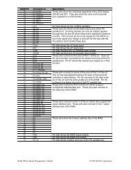
<strong>VGA</strong> <strong>Signal</strong> Generator in VHDLA VHDL version of <strong>the</strong> <strong>VGA</strong> signal generator is shown in Listing 5. The inputs and outputs of <strong>the</strong> circuit as definedin <strong>the</strong> entity declaration are as follows:reset: This line declares an input which will reset all <strong>the</strong> o<strong>the</strong>r circuitry to a known state.clock: The input for <strong>the</strong> 12 MHz clock of <strong>the</strong> <strong>XS</strong> <strong>Board</strong> is declared here. This clock sets <strong>the</strong> maximum rate at whichpixels can be sent to <strong>the</strong> monitor. The time interval <strong>with</strong>in each line for transmitting viewable pixels is 25.17µs, so this <strong>VGA</strong> generator circuit can only put a maximum of 25.17 ms × 12 MHz = 302 pixels on each line.For purposes of storing images in <strong>the</strong> RAM, it is convenient to reduce this to 256 pixels per line and blank <strong>the</strong>remaining 46 pixels. Half of <strong>the</strong>se blank pixels are placed before <strong>the</strong> 256 viewable pixels and half are placedafter <strong>the</strong>m on a line. This centers <strong>the</strong> viewable pixels between <strong>the</strong> left and right edges of <strong>the</strong> monitor screen.hsyncb, vsyncb: The outputs for <strong>the</strong> horizontal and vertical sync pulses are declared. The hsyncb output is declaredas a buffer because it will also be referenced <strong>with</strong>in <strong>the</strong> architecture section as a clock for <strong>the</strong> vertical linecounter.rgb: The outputs which control <strong>the</strong> red, green, and blue color guns of <strong>the</strong> monitor are declared here. Each gun iscontrolled by two bits, so <strong>the</strong>re are four possible intensities for each color. Thus, this circuit can produce 4 × 4× 4 = 64 different colors.addr, data: These lines declare <strong>the</strong> outputs for driving <strong>the</strong> address lines of <strong>the</strong> RAM and <strong>the</strong> inputs for receiving <strong>the</strong>data from <strong>the</strong> RAM.csb, oeb, web: These are <strong>the</strong> declarations for <strong>the</strong> outputs which drive <strong>the</strong> control lines of <strong>the</strong> RAM.The preamble of <strong>the</strong> architecture section declares <strong>the</strong> following resources:hcnt, vcnt: The counters that store <strong>the</strong> current horizontal position <strong>with</strong>in a line of pixels and <strong>the</strong> vertical position of<strong>the</strong> line on <strong>the</strong> screen are declared on <strong>the</strong>se lines. We will call <strong>the</strong>se <strong>the</strong> horizontal or pixel counter, and <strong>the</strong>vertical or line counter, respectively. The line period is 31.77 µs which is 381 clock cycles, so <strong>the</strong> pixel counterneeds at least nine bits of resolution. Each frame is composed of 528 video lines (only 480 are visible, <strong>the</strong> o<strong>the</strong>r48 are blanked), so a ten bit counter is needed for <strong>the</strong> line counter.pixrg: This is <strong>the</strong> declaration for <strong>the</strong> eight-bit register that stores <strong>the</strong> four pixels received from <strong>the</strong> RAM.blank, pblank: This line declares <strong>the</strong> video blanking signal and its registered counterpart that is used in <strong>the</strong> nextpipeline stage.Within <strong>the</strong> main body of <strong>the</strong> architecture section, <strong>the</strong> following processes are executed:A: This process describes <strong>the</strong> operation of <strong>the</strong> horizontal pixel counter. The counter is asynchronously set to zerowhen <strong>the</strong> reset input is high. The counter increments on <strong>the</strong> rising edge of each pixel clock. The range for <strong>the</strong>horizontal pixel counter is [0,380]. When <strong>the</strong> counter reaches 380, it rolls over to 0 on <strong>the</strong> next cycle. Thus, <strong>the</strong>counter has a period of 381 pixel clocks. With a pixel clock of 12 MHz, this translates to a period of 31.75 µs.B: This process describes <strong>the</strong> operation of <strong>the</strong> vertical line counter. The counter is asynchronously set to zero when<strong>the</strong> reset input is high. The counter increments on <strong>the</strong> rising edge of <strong>the</strong> horizontal sync pulse after a line ofpixels is completed. The range for <strong>the</strong> horizontal pixel counter is [0,527]. When <strong>the</strong> counter reaches 527, it rollsover to 0 on <strong>the</strong> next cycle. Thus, <strong>the</strong> counter has a period of 528 lines. Since <strong>the</strong> duration of a line of pixels is31.75 µs, this makes <strong>the</strong> frame interval equal to 16.76 ms.