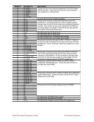
Lines 19,20: The counters that store <strong>the</strong> current horizontal position <strong>with</strong>in a line of pixels and <strong>the</strong> vertical position of<strong>the</strong> line on <strong>the</strong> screen are declared on <strong>the</strong>se lines. We will call <strong>the</strong>se <strong>the</strong> horizontal or pixel counter, and <strong>the</strong>vertical or line counter, respectively. The line period is 31.77 µs which is 381 clock cycles, so <strong>the</strong> pixel counterneeds at least nine bits of resolution. Each frame is composed of 528 video lines (only 480 are visible, <strong>the</strong> o<strong>the</strong>r48 are blanked), so a ten bit counter is needed for <strong>the</strong> line counter.Line 21: This is <strong>the</strong> declaration for <strong>the</strong> eight-bit register that stores <strong>the</strong> four pixels received from <strong>the</strong> RAM.Lines 22,23: This line declares <strong>the</strong> video blanking signal and its registered counterpart that is used in <strong>the</strong> nextpipeline stage.Lines 25-31: These lines define aliases for <strong>the</strong> signals that were declared earlier. Not that <strong>the</strong> current active pixel isdefined to be in <strong>the</strong> lower two bits of <strong>the</strong> pixel byte.Line 35: The length of carry lookahead is set to one position, so all adders that follow will be of <strong>the</strong> simple, spaceefficientripple-carry type. This conserves logic gates at <strong>the</strong> expense of speed.Lines 37,38: The pixel and line counters are set to zero when <strong>the</strong> reset input is high. The reset is only activated at<strong>the</strong> start of <strong>the</strong> operation of <strong>the</strong> <strong>VGA</strong> generator circuitry and is not used during <strong>the</strong> normal operations.Lines 39,40: The pixel counter is incremented on <strong>the</strong> rising edge of <strong>the</strong> 12 MHz pixel clock. The vertical linecounter is clocked by <strong>the</strong> rising edge of <strong>the</strong> horizontal blanking pulse, so it increments only after a line of pixelsis completed.Lines 42,43: The active-low horizontal and vertical sync registers are set to high values when <strong>the</strong> reset input is high.Lines 44,45: The registered horizontal sync output is updated on every pixel clock. The registered vertical syncoutput is updated whenever a line of video is completed. The values that are placed in <strong>the</strong>se registers at specifictimes are determined in <strong>the</strong> statements which follow.Line 48: This line sets <strong>the</strong> range for <strong>the</strong> horizontal pixel counter to be [0,380]. When <strong>the</strong> counter reaches 380, itrolls over to 0. Thus, <strong>the</strong> counter has a period of 381 pixel clocks. With a pixel clock of 12 MHz, this translatesto a period of 31.75 µs.Line 50: This line determines <strong>the</strong> active and inactive intervals of <strong>the</strong> registered horizontal sync output. The syncsignal goes low on <strong>the</strong> cycle after <strong>the</strong> pixel counter reaches 291 and continues until <strong>the</strong> cycle after <strong>the</strong> counterreaches 337. This gives a low horizontal sync pulse of (337-291)=46 pixel clocks. With a pixel clock of 12MHz, this translates to a low-going horizontal sync pulse of 3.83 µs. The sync pulse starts 292 clocks after <strong>the</strong>line of pixels begins, which translates to 24.33 µs. This is less than <strong>the</strong> 26.11 µs we stated before. Thedifference of 1.78 ms translates to 21 pixel clocks. This time interval corresponds to <strong>the</strong> 23 blank pixels that areplaced prior to <strong>the</strong> 256 viewable pixels (minus two clock cycles for pipelining delays).Line 52: This line sets <strong>the</strong> range for <strong>the</strong> vertical line counter to be [0,527]. When <strong>the</strong> counter reaches 527, it rollsover to 0. Thus, <strong>the</strong> counter has a period of 528 lines. Since <strong>the</strong> duration of a line of pixels is 31.75 µs, thismakes <strong>the</strong> frame interval equal to 16.76 ms.Line 54: This line determines <strong>the</strong> active and inactive intervals of <strong>the</strong> registered vertical sync output. The sync signalgoes low on <strong>the</strong> cycle after <strong>the</strong> line counter reaches 493 and continues until <strong>the</strong> cycle after <strong>the</strong> counter reaches495. This gives a low vertical sync pulse of (495-493)= 2 lines. With a line interval of 31.75 µs, this translatesto a low-going vertical sync pulse of 63.5 µs. The vertical sync pulse starts 494 × 31.75 µs = 15.68 ms after <strong>the</strong>beginning of <strong>the</strong> first video line.Line 56: The activation of <strong>the</strong> video blanking control signal is set on this line. The video is blanked after 256 pixelson a line are displayed, or after 480 lines are displayed.
Lines 58-60: The blanking signal is stored in a register so it can be used during <strong>the</strong> next stage of <strong>the</strong> pipeline when<strong>the</strong> color is computed.Lines 63,64: On <strong>the</strong>se lines, <strong>the</strong> RAM is permanently selected and writing to <strong>the</strong> RAM is disabled. This makes <strong>the</strong>RAM look like a ROM which stores video data.Line 65: The outputs from <strong>the</strong> RAM are disabled when <strong>the</strong> video is blanked since <strong>the</strong>re is no need for pixels during<strong>the</strong> blanking intervals. This isn’t really necessary since no o<strong>the</strong>r circuit is trying to access <strong>the</strong> RAM.Line 71: The address in RAM where <strong>the</strong> next four pixels are stored is calculated by concatenating <strong>the</strong> lower ninebits of <strong>the</strong> line counter <strong>with</strong> bits 7,6,5,4,3 and 2 of <strong>the</strong> pixel counter. With this arrangement, <strong>the</strong> line counterstores <strong>the</strong> address of one of 2 9 = 512 pages. Each page contains 2 6 = 64 bytes. Each byte contains four pixels,so each page stores one line of 256 pixels. The pixel counter increments through <strong>the</strong> bytes of a page to get <strong>the</strong>pixels for <strong>the</strong> current line. (Note that we don’t need to use bits 1 and 0 of <strong>the</strong> pixel counter when computing <strong>the</strong>RAM address since each byte contains four pixels.) After <strong>the</strong> line is displayed, <strong>the</strong> line counter is incrementedto point to <strong>the</strong> next page.Lines 73,74: The register that holds <strong>the</strong> byte of pixel data from RAM is cleared when <strong>the</strong> <strong>VGA</strong> circuit is reset. Theregister is updated on <strong>the</strong> rising edge of each pixel clock.Lines 80-82: The pixel register is loaded <strong>with</strong> data from <strong>the</strong> RAM whenever <strong>the</strong> lowest two bits of <strong>the</strong> pixel counterare both zero. The active pixel is always in <strong>the</strong> lower two bits of <strong>the</strong> register. Each pixel in <strong>the</strong> RAM data byteis shifted into <strong>the</strong> active position by right shifting <strong>the</strong> register two bits on each rising clock edge.Line 86: The register that holds <strong>the</strong> red, green, and blue color gun control bits is set to zero when <strong>the</strong> reset input ishigh.Line 87: The color register is clocked on <strong>the</strong> rising edge of <strong>the</strong> pixel clock since this is <strong>the</strong> rate at which new pixelvalues arrive.Lines 88-96: This truth-table defines <strong>the</strong> color gun control bits which are stored in <strong>the</strong> color register as a function of<strong>the</strong> pixel value and <strong>the</strong> blanking input. When <strong>the</strong> pipelined blanking input is low (lines 87-90), <strong>the</strong> colordisplayed on <strong>the</strong> monitor is red, green, blue, or white depending upon whe<strong>the</strong>r <strong>the</strong> pixel value is 00, 01, 10, or11, respectively. When <strong>the</strong> pipelined blanking input is high (lines 91-94), <strong>the</strong> color register is loaded <strong>with</strong> zerowhich will display <strong>the</strong> color black on <strong>the</strong> monitor.