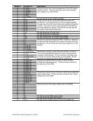
C: This process describes <strong>the</strong> operation of <strong>the</strong> horizontal sync pulse generator. The horizontal sync is set to itsinactive high level when <strong>the</strong> reset is activated. During normal operations, <strong>the</strong> horizontal sync output is updatedon every pixel clock. The sync signal goes low on <strong>the</strong> cycle after <strong>the</strong> pixel counter reaches 291 and continuesuntil <strong>the</strong> cycle after <strong>the</strong> counter reaches 337. This gives a low horizontal sync pulse of (337-291)=46 pixelclocks. With a pixel clock of 12 MHz, this translates to a low-going horizontal sync pulse of 3.83 µs. The syncpulse starts 292 clocks after <strong>the</strong> line of pixels begins, which translates to 24.33 µs. This is less than <strong>the</strong> 26.11 µswe stated before. The difference of 1.78 ms translates to 21 pixel clocks. This time interval corresponds to <strong>the</strong>23 blank pixels that are placed prior to <strong>the</strong> 256 viewable pixels (minus two clock cycles for pipelining delays).D: This process describes <strong>the</strong> operation of <strong>the</strong> vertical sync pulse generator. The vertical sync is set to its inactivehigh level when <strong>the</strong> reset is activated. During normal operations, <strong>the</strong> vertical sync output is updated after everyline of pixels is completed. The sync signal goes low on <strong>the</strong> cycle after <strong>the</strong> line counter reaches 493 andcontinues until <strong>the</strong> cycle after <strong>the</strong> counter reaches 495. This gives a low vertical sync pulse of (495-493)= 2lines. With a line interval of 31.75 µs, this translates to a low-going vertical sync pulse of 63.5 µs. The verticalsync pulse starts 494 × 31.75 µs = 15.68 ms after <strong>the</strong> beginning of <strong>the</strong> first video line.E: This line describes <strong>the</strong> computation of <strong>the</strong> combinatorial blanking signal. The video is blanked after 256 pixelson a line are displayed, or after 480 lines are displayed.F: This process describes <strong>the</strong> operation of <strong>the</strong> pipelined video blanking signal. Within <strong>the</strong> process, <strong>the</strong> blankingsignal is stored in a register so it can be used during <strong>the</strong> next stage of <strong>the</strong> pipeline when <strong>the</strong> color is computed.G: On <strong>the</strong>se lines, <strong>the</strong> RAM is permanently selected and writing to <strong>the</strong> RAM is disabled. This makes <strong>the</strong> RAM looklike a ROM which stores video data. Also <strong>the</strong> outputs from <strong>the</strong> RAM are disabled when <strong>the</strong> video is blankedsince <strong>the</strong>re is no need for pixels during <strong>the</strong> blanking intervals. This isn’t really necessary since no o<strong>the</strong>r circuitis trying to access <strong>the</strong> RAM.H: The address in RAM where <strong>the</strong> next four pixels are stored is calculated by concatenating <strong>the</strong> lower nine bits of<strong>the</strong> line counter <strong>with</strong> bits 7,6,5,4,3 and 2 of <strong>the</strong> pixel counter. With this arrangement, <strong>the</strong> line counter stores <strong>the</strong>address of one of 2 9 = 512 pages. Each page contains 2 6 = 64 bytes. Each byte contains four pixels, so eachpage stores one line of 256 pixels. The pixel counter increments through <strong>the</strong> bytes of a page to get <strong>the</strong> pixels for<strong>the</strong> current line. (Note that we don’t need to use bits 1 and 0 of <strong>the</strong> pixel counter when computing <strong>the</strong> RAMaddress since each byte contains four pixels.) After <strong>the</strong> line is displayed, <strong>the</strong> line counter is incremented topoint to <strong>the</strong> next page.I: This process describes <strong>the</strong> operation of <strong>the</strong> register that holds <strong>the</strong> byte of pixel data read from RAM. The registeris asynchronously cleared when <strong>the</strong> <strong>VGA</strong> circuit is reset. The register is updated on <strong>the</strong> rising edge of eachpixel clock. The pixel register is loaded <strong>with</strong> data from <strong>the</strong> RAM whenever <strong>the</strong> lowest two bits of <strong>the</strong> pixelcounter are both zero. The active pixel is always in <strong>the</strong> lower two bits of <strong>the</strong> register. Each pixel in <strong>the</strong> RAMdata byte is shifted into <strong>the</strong> active position by right shifting <strong>the</strong> register two bits on each rising clock edge.J: this process describes <strong>the</strong> process by which <strong>the</strong> current active pixel is mapped into <strong>the</strong> six bits which drive <strong>the</strong>red, green and blue color guns. The register is set to zero (which displays as <strong>the</strong> color black) when <strong>the</strong> resetinput is high. The color register is clocked on <strong>the</strong> rising edge of <strong>the</strong> pixel clock since this is <strong>the</strong> rate at whichnew pixel values arrive. The value clocked into <strong>the</strong> register is a function of <strong>the</strong> pixel value and <strong>the</strong> blankinginput. When <strong>the</strong> pipelined blanking input is low (inactive), <strong>the</strong> color displayed on <strong>the</strong> monitor is red, green,blue, or white depending upon whe<strong>the</strong>r <strong>the</strong> pixel value is 00, 01, 10, or 11, respectively. When <strong>the</strong> pipelinedblanking input is high, <strong>the</strong> color register is loaded <strong>with</strong> zero (black).
library IEEE;use IEEE.std_logic_1164.all;use IEEE.std_logic_unsigned.all;entity vgacore isport(reset: in std_logic; -- resetclock: in std_logic; -- <strong>VGA</strong> dot clockhsyncb: buffer std_logic; -- horizontal (line) syncvsyncb: out std_logic; -- vertical (frame) syncrgb: out std_logic_vector(5 downto 0); -- red,green,blue colorsaddr: out std_logic_vector(14 downto 0); -- address to video RAMdata: in std_logic_vector(7 downto 0); -- data from video RAMcsb: out std_logic; -- video RAM chip enableoeb: out std_logic; -- video RAM output enable);end vgacore;web: out std_logic-- video RAM write enablearchitecture vgacore_arch of vgacore issignal hcnt: std_logic_vector(8 downto 0); -- horizontal pixel countersignal vcnt: std_logic_vector(9 downto 0); -- vertical line countersignal pixrg: std_logic_vector(7 downto 0); -- byte register for 4 pixelssignal blank: std_logic;-- video blanking signalsignal pblank: std_logic;-- pipelined video blanking signalbeginA: process(clock,reset)begin-- reset asynchronously clears pixel counterif reset='1' <strong>the</strong>nhcnt