VGA Signal Generation with the XS Board - Xess
VGA Signal Generation with the XS Board - Xess
VGA Signal Generation with the XS Board - Xess

Create successful ePaper yourself
Turn your PDF publications into a flip-book with our unique Google optimized e-Paper software.
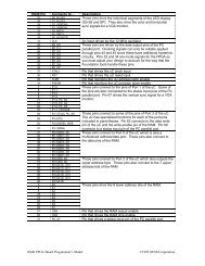
stage 3: The binary color outputs are applied to <strong>the</strong> DAC which sets <strong>the</strong> intensity levels for <strong>the</strong> monitor’s color guns.The actual pixel is painted on <strong>the</strong> screen during this stage.Figure 3: Pipelining of <strong>VGA</strong> signal generation tasks.<strong>VGA</strong> <strong>Signal</strong> Generator in ABELThe pseudocode and pipeline timing will help us to understand <strong>the</strong> ABEL code for a <strong>VGA</strong> signal generator inListing 2:Line 6: This line declares an input which will reset all <strong>the</strong> o<strong>the</strong>r circuitry to a known state.Line 7: The input for <strong>the</strong> 12 MHz clock of <strong>the</strong> <strong>XS</strong> <strong>Board</strong> is declared here. This clock sets <strong>the</strong> maximum rate atwhich pixels can be sent to <strong>the</strong> monitor. The time interval <strong>with</strong>in each line for transmitting viewable pixels is25.17 µs, so this <strong>VGA</strong> generator circuit can only put a maximum of 25.17 ms × 12 MHz = 302 pixels on eachline. For purposes of storing images in <strong>the</strong> RAM, it is convenient to reduce this to 256 pixels per line and blank<strong>the</strong> remaining 46 pixels. Half of <strong>the</strong>se blank pixels are placed before <strong>the</strong> 256 viewable pixels and half areplaced after <strong>the</strong>m on a line. This centers <strong>the</strong> viewable pixels between <strong>the</strong> left and right edges of <strong>the</strong> monitorscreen.Lines 8,9: The outputs for <strong>the</strong> horizontal and vertical sync pulses are declared. These outputs are registered to makesure <strong>the</strong>y are not affected by combinational logic delays in <strong>the</strong> <strong>VGA</strong> generator circuitry.Lines 10-12: The outputs which control <strong>the</strong> red, green, and blue color guns of <strong>the</strong> monitor are declared here. Eachgun is controlled by two bits, so <strong>the</strong>re are four possible intensities for each color. Thus, this circuit can produce4 × 4 × 4 = 64 different colors.Lines 13,14: These lines declare <strong>the</strong> outputs for driving <strong>the</strong> address lines of <strong>the</strong> RAM and <strong>the</strong> inputs for receiving<strong>the</strong> data from <strong>the</strong> RAM.Lines 15-17: These are <strong>the</strong> declarations for <strong>the</strong> outputs which drive <strong>the</strong> control lines of <strong>the</strong> RAM.