48ES and 51ES NXT Stager Controller - Pentair Residential Filtration
48ES and 51ES NXT Stager Controller - Pentair Residential Filtration
48ES and 51ES NXT Stager Controller - Pentair Residential Filtration

You also want an ePaper? Increase the reach of your titles
YUMPU automatically turns print PDFs into web optimized ePapers that Google loves.
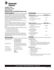
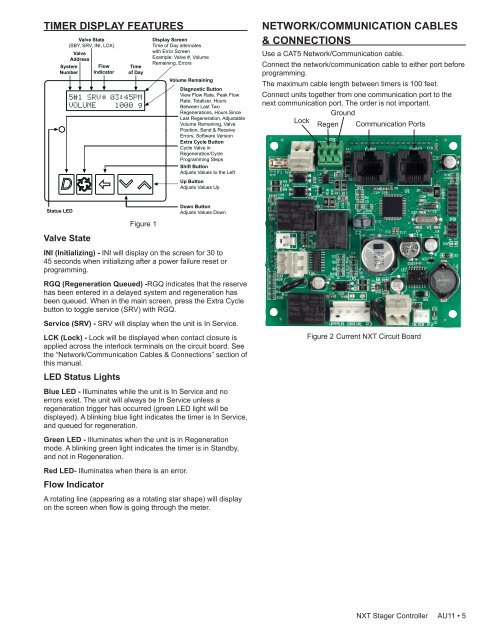
TIMER DISPLAY FEATURESValve State(SBY, SRV, INI, LCK)ValveAddressSystemNumberFlowIndicatorTimeof DayDisplay ScreenTime of Day alternateswith Error ScreenExample: Valve #, VolumeRemaining, ErrorsVolume RemainingDiagnostic ButtonView Flow Rate, Peak FlowRate, Totalizer, HoursBetween Last TwoRegenerations, Hours SinceLast Regeneration, AdjustableVolume Remaining, ValvePosition, Send & ReceiveErrors, Software VersionExtra Cycle ButtonCycle Valve inRegeneration/CycleProgramming StepsShift ButtonAdjusts Values to the LeftUp ButtonAdjusts Values UpNETWORK/COMMUNICATION CABLES& CONNECTIONSUse a CAT5 Network/Communication cable.Connect the network/communication cable to either port beforeprogramming.The maximum cable length between timers is 100 feet.Connect units together from one communication port to thenext communication port. The order is not important.GroundLockRegen Communication PortsStatus LEDValve StateFigure 1Down ButtonAdjusts Values DownINI (Initializing) - INI will display on the screen for 30 to45 seconds when initializing after a power failure reset orprogramming.RGQ (Regeneration Queued) -RGQ indicates that the reservehas been entered in a delayed system <strong>and</strong> regeneration hasbeen queued. When in the main screen, press the Extra Cyclebutton to toggle service (SRV) with RGQ.Service (SRV) - SRV will display when the unit is In Service.LCK (Lock) - Lock will be displayed when contact closure isapplied across the interlock terminals on the circuit board. Seethe “Network/Communication Cables & Connections” section ofthis manual.LED Status LightsBlue LED - Illuminates while the unit is In Service <strong>and</strong> noerrors exist. The unit will always be In Service unless aregeneration trigger has occurred (green LED light will bedisplayed). A blinking blue light indicates the timer is In Service,<strong>and</strong> queued for regeneration.Green LED - Illuminates when the unit is in Regenerationmode. A blinking green light indicates the timer is in St<strong>and</strong>by,<strong>and</strong> not in Regeneration.Red LED- Illuminates when there is an error.Flow IndicatorA rotating line (appearing as a rotating star shape) will displayon the screen when flow is going through the meter.Figure 2 Current <strong>NXT</strong> Circuit Board<strong>NXT</strong> <strong>Stager</strong> <strong>Controller</strong> AU11 • 5