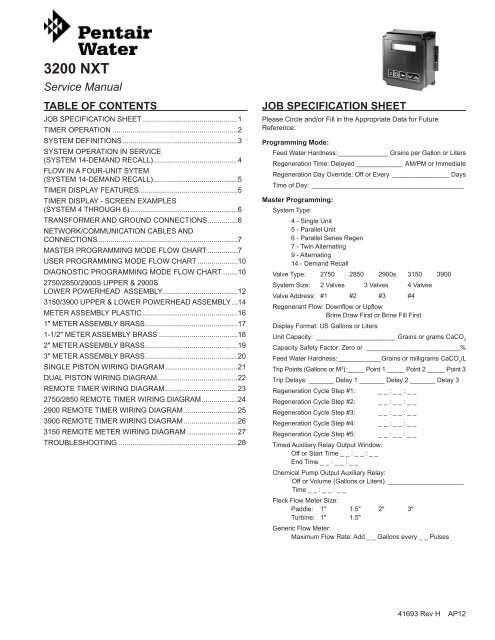
3200NXT Service Manual 41693 Rev H Current - Pentair ...
3200NXT Service Manual 41693 Rev H Current - Pentair ...
3200NXT Service Manual 41693 Rev H Current - Pentair ...
- No tags were found...
You also want an ePaper? Increase the reach of your titles
YUMPU automatically turns print PDFs into web optimized ePapers that Google loves.
AND CONNECTIONSUse either a CAT3 or CAT5 Network/Communication cable.Connect the network/communication cable first beforeprogramming.The maximum cable length between timers is 100 feet.Connect each unit together from one communication port to thenext communication port. It does not matter which one goes tothe next one.LockGroundRegenCommunication PortsFigure 2 <strong>Current</strong> NXT Circuit BoardMASTER PROGRAMMING MODE FLOWCHARTCAUTION Before entering Master Programming, pleasecontact your local professional water dealer.NOTE: Depending on current option settings, somedisplays cannot be viewed or set.Entering Master Programming Mode1. Press and hold the Shift and Up buttons for 5 seconds.Press the Extra Cycle button once per display until alldisplays are viewed and Normal Display is resumed. Optionsetting displays may be changed as required by pressingeither Up or Down button. Use the Shift button to move onespace to the left.2. Depending on current valve programming, certain displaysmay not be viewed or set.NOTE: If the "D" button is pressed while in masterprogramming, no changes will be saved.Exiting Master Programming Mode1. Press the Extra Cycle button once per display until allare viewed. Master Programming Mode is exited and thenormal display screen appears.2. To exit the Master Programming Mode without savingchanges, press the Diagnostic button.NOTE: If no keypad activity is made for 5 minutes whilein the Master Programming Mode, or if there is apower failure, no changes will be saved, and theunit will go back to the main display screen.ResetsSoft Reset: Press and hold the Up and Down buttons for 25seconds until 12:00PM (or 12:00HR) appears. This resets allparameters except for the flow meter totalizer volume.Master Reset: Hold the Extra Cycle button while powering upthe unit. This resets all of the parameters in the unit. Checkand verify the choices selected in Master Programming Mode.NOTE: If the "D" button is pressed while in masterprogramming, no changes will be saved.SELECT LANGUAGE:ENGLISHOptions: EnglishEspanolPortuguesDeutschFrancaisExample:EnglishSYSTEM TYPE: 4SINGLE UNITExample:System Type 4, Single UnitOptions: System 4 (single unit)System 5 (2-4 units) Parallel InterlockSystem 6 (2-4 units) Parallel Series RegenerationSystem 7 (2 units) AlternatingSystem 9 (2-4 units) AlternatingSystem 14 (2-4 units) Demand RecallVALVE ADDRESS:#2Example:Valve Address #2 (Second Control Valve) (Default)Options: Valve Address #1 (First Control Valve)Valve Address #2 (Second Control Valve) (Default)Valve Address #3 (Third Control Valve)Valve Address #4 (Fourth Control Valve)NOTE: This screen will not display for System Type 4.SYSTEM SIZE:2 VALVESExample:2 Valves in the System (Default)Options: 2 Valves in the System (Default)3 Valves in the System4 Valves in the SystemRange: 2 to 4 Valves in the SystemNOTE: This screen will not display for System Type 4.3200 NXT FE12 • 7
VALVE ADDRESS:#2Example:Valve Address #2 (Second Control Valve) (Default)MASTER PROGRAMMING MODE FLOWCHART continuedOptions: Valve Address #1 (First Control Valve)Valve Address #2 (Second Control Valve) (Default)Valve Address #3 (Third Control Valve)Valve Address #4 (Fourth Control Valve)NOTE: This screen will not display for System Type 4.SYSTEM SIZE:2 VALVESOptions: 2 Valves in the System (Default)3 Valves in the System4 Valves in the SystemRange: 2 to 4 Valves in the SystemNOTE: This screen will not display for System Type 4.REGEN TYPE:TIME CLK DELAYEDOptions: Time Clock Delayed (System 4 Only) (Default)Meter Immediate (All System Types)Meter Delayed Fixed Reserve (Systems 4 & 6 Only)VALVE TYPE:2750Options: 2750 (Default)2850290031503900Stager - Notch CamREGENERANT FLOW:DOWNFLOWOptions: Downflow (Default)Up FlowUF Fill FirstREMOTE SIGNALSTART: 00:06:00Example:2 Valves in the System (Default)Example:Time Clock Delayed (Default)Example:2750 (Default)Example:Downflow (Default)Example:00:06:00 (Default)(Hours:Minutes:Seconds)Options: 00:06:00 (Default)Range: 1 second to 99 minutes (1 hour, 39 minutes)NOTE: This display will not be viewed in System 4DISPLAY FORMAT:US-GALLONSExample:U.S. Gallons (Default)Options: U.S. - Gallons (Default)Eu Metric - Liters (Metric)NOTE: In U.S. - Gallons mode, the display will be in 12-hour time.NOTE: In European Units - Liters (Metric) mode, the display will be in24-hour time.2750Options: 2750 (Default)2850290031503900Stager - Notch CamDISPLAY FORMAT:US-GALLONSUNIT CAPACITY:00000000 GRAINSFEED WATERHARDNESS: 15 GPG2750 (Default)Trip Points 1, 2, and 3 (System 14 only)REGENERANT FLOW: Example:DOWNFLOWThis program step selects up toDownflowthree(Default)Trip Points programmedon the master Options: timer Downflow only (Default) (Valve Address #1).Up FlowThe actual required UF Fill number First of Trip Points in a system is oneless than the number of valves in the system.Trip Point 1 REMOTE represents SIGNALthe system Example: flow rate at which a secondSTART: 00:06:00 00:06:00 (Default)valve will be brought In <strong>Service</strong> (Hours:Minutes:Seconds)or Standby.Options: 00:06:00 (Default)Trip Point Range: 2 represents 1 second to 99 the minutes system (1 hour, flow 39 minutes) rate at which a thirdvalve will be NOTE: brought This display In <strong>Service</strong> will not be viewed or Standby. in System 4Trip Point 3 represents the system flow rate at which a fourthvalve will be brought In <strong>Service</strong> or Standby.Example:U.S. Gallons (Default)Trip Point Options: 1 U.S. - Gallons Trip (Default) Point 2 Trip Point 3Eu Metric - Liters (Metric)In1 NOTE: In European Units - Liters (Metric) mode, the display will be inRange: NOTE:– 997 GPMU.S. U.S.: - Gallons Value mode, of the Trip display Point will1 plus 1 to 998be U.S.: in 12-hour Trip time. Point 2 plus1 to 99924-hour time.Range: Metric: Value of Trip Metric: Trip Point 20.01 – 9.97 M 3 /M Point 1 plus .01 to 9.98 plus 0.01 to 9.99Example:Grains (Default)Trip Delays Options: 1, Grains 2, (in and U.S. Format) 3 (System (Default) 14 only)Grams (in Metric Format)This program step selects each Trip Delay time that isRange: 1 to 9,900,000 Grain Capacity in U.S. Formataddressed with each 1 to 198,000 Trip grams Point CaCO3 and Capacity will be in Metric programmed Format onthe Master NOTE: timer Use only the Shift (Valve button Address to move to the #1). left. The Trip Delay timerepresents a minimum amount of time the system flow rate isrequired to CAPACITY be equal SAFETY or greater Example: than the Trip Points to bringFACTOR: 00% 00% (Default)a unit In <strong>Service</strong>. It also is the minimum amount of time thesystem flow Range: rate 0 is to 50% required to be less than the Trip Points toNOTE: Use the Shift button to move to the left.remove a unit from In <strong>Service</strong> to Standby.Trip Delay 1 Trip Delay 2 Trip Delay 3Default: 30 SecondsExample:15 GPG (U.S. Format) (Default)Range: 1 to 199 Grains/Gallon (U.S. Format)20 to 1,999 miligrams CaCO3/L (Metric Format)NOTE: Use the Shift button Range: to move to the left. Range:NOTE: This screen will 30 only - 99 display Secondsthe lead unit 30 for - System 99 Seconds Types 6 & 7.For all other System Types, it will display for all units.Range:30 - 99 SecondsTRIP POINT 1:000 gpmUNIT CAPACITY:00000000 GRAINSExample:Grains (Default)Options: Grains (in U.S. Format) (Default)Grams (in Metric Format)Range: 1 to 9,900,000 Grain Capacity in U.S. Format1 to 198,000 grams CaCO3 Capacity in Metric FormatNOTE: Use the Shift button to move to the left.NOTE: Display will not appear unless timer is programmed as valve position#1. Use the Shift button to change each decimal position.CAPACITY SAFETYFACTOR: 00%Example:00% (Default)TRIP DELAY 1:30 SECONDSRange: 0 to 50%NOTE: Use the Shift button to move to the left.FEED WATERHARDNESS: 15 GPGExample:15 GPG (U.S. Format) (Default)Range: 1 to 199 Grains/Gallon (U.S. Format)20 to 1,999 miligrams CaCO3/L (Metric Format)NOTE: Use the Shift button to move to the left.NOTE: This screen will only display on the lead unit for System Types 6 & 7.For all other System Types, it will display for all units.TRIP POINT 1:000 gpmNOTE: Display will not appear unless timer is programmed as valve position#1. Use the Shift button to move one space to the left.TRIP POINT 2:gpmNOTE: Display will not appear unless timer is programmed as valve position#1. System size must be 3 or 4 to appear. Use the Shift button to move onespace to the left.TRIP DELAY 2:30 SECONDSNOTE: Display will not appear unless timer is programmed as valve position#1. Use the Shift button to change each decimal position.8 • 3200 NXT FE12TRIP DELAY 1:30 SECONDSNOTE: Display will not appear unless timer is programmed as valve position#1. System size must be 3 or 4 to appear. Use the Shift button to move onespace to the left.TRIP POINT 3:gpm
MAXIMUM FLOWRATE: 0000 gpmExample:Maximum Flow Rate of 0 gpmMASTER PROGRAMMING MODE FLOWRange: 20 - 2,000 gpm (U.S. Format)CHART continued20 - 200.0 L (Metric Format)NOTE: Only displayed if “Generic” is chosen for the flow meter.ADD 01 GALLONSEVERY 001 PULSESOptions: Gallons (U.S. Format)Liters (Metric Format)Range: 1 - 255Gallons (U.S. Format)0.1 - 09.9 L (Metric Format)Pulses: 1 - 255NOTE: Only displayed if “Generic” is chosen for the flow meter.PROGRAMMING UNITPLEASE WAIT...Example:Add 1 Gallon for Each Pulse in U.S. FormatExample:Master Programming Mode is ExitingUSER PROGRAMMING MODE FLOWCHARTEntering User Programming ModeHold the Set Up and Set Down buttons for 5 seconds.NOTE: User Mode is only displayed when a metered optionis chosen under System Type. Depending oncurrent option settings, some displays cannot beviewed or set.NOTE: User Mode cannot be entered on the Lag unit forSystem 6.DIAGNOSTIC PROGRAMMING MODEFLOW CHARTEntering Diagnostic Programming Mode1. Push and release the "D" button.2. Press the Extra Cycle button once per display until alldisplays are viewed and Normal Display is resumed.3. Push and release the"D" button at anytime duringdiagnostic mode and the timer will exit the mode.4. Depending on the current controller programming, certaindisplays may not be able to be viewed or set.Overview Diagnostic ModeThe current diagnostic will be displayed until Extra Cycle key ispressed. There is no time limit on each display. The timer willdisplay local information, not system information. In the eventof a regeneration occurring while displaying diagnostics, theregeneration step and time remaining will be displayed. Whenregeneration has been completed, the display will return to themain screen.CURRENT FLOWRATE:0 gpmPEAK FLOW RATE:0 gpmExample:Flow rate at this time.Example:Peak flow since last regeneration.TOTALIZER:130 gExample:Gallons at the outlet since installation.FEED WATERHARDNESS:gpgLAST TWO REGENS:0 HOURSExample:Hours between the last regeneration and theone before it.LAST REGEN0 HOURSExample:Hours since last regeneration.REGENERATION DAYOVERRIDE: OFFVOLUME REMAIN:1000 gExample:Volume remaining (can be adjusted).NOTE: If a System 6, Unit #1 of “Tank Remaining” will display “SystemRemaining”.REGENERATION DAYOVERRIDE:99 DAYSVALVE ADDRESS#2Example:Controller unit number.REGENERATIONTIME: 02:00AMVERSION:X.XXExample:Installed software level of the controller in use.10 • 3200 NXT FE12
NXT Multi LanguageProgramming Parameters and RangesSystem Type4TimeClockValve Address 1 2 3 4 1 2 3 4 1 2 1 2 3 4 1 2 3 4Select Language x x x x x x x x x x x x x x x x x x x x xSystem Size x x x x xRegen Type x x x x x x x x x x x x x x x x x x x x xValve Type x x x x x x x x x x x x x x x x x x x x xRegenerant Flow x x x x x x x x x x x x x x x x x x x x xRemote Signal Start x x x x x x x x x x x x xGallons LitersDisplay Format x x x x x x x x x x x x x x x x x x x x x US - Gallons EU - Metric-LitersUnit Capacity x x x x x x x x x x x x x x x x x 1 - 9900000 Grains 1 - 198000 gCaCO3Capacity Safety Factor x x x x x x x x x x x x x x x x x0- 50%Feed Water Hardness x x x x x x x x x x x x x x x x x 1 - 199 Grains/Gallons 1 - 1999 mgLTrip Point 1 x 0 - 997gpm 0 - 3997 LpmTrip Delay 1 x 30 - 99 Seconds 30 - 99 SecondsTrip Point 2 x Trip Point 1 + 1 - 998 gpm Trip Point 1 + 1 - 3998 LpmTrip Delay 2 x 30 - 99 Seconds 30 - 99 SecondsTrip Point 3 x Trip Point 2 + 1 - 999 gpm Trip Point 2 + 1 - 3999 LpmTrip Delay 3 x 30 - 99 Seconds 30 - 99 SecondsRegeneration Day Override x x x x x x x x x x x x x x x x xOff, 1 - 99Regeneration Time x o o o o o o o o o o o o o o o o o 12:00 a.m. - 11:59 p.m. 00:00 - 23:59 HourCycle 1 x x x x x x x x x x x x x x x x x x x x xCycle 2 x x x x x x x x x x x x x x x x x x x x xCycle 3 x x x x x x x x x x x x x x x x x x x x xCycle 4 x x x x x x x x x x x x x x x x x x x x xCycle 5 x x x x x x x x x x x x x x x x x x x x xAuxiliary Relay x x x x x x x u x x x u x x x x x x x x xAux Relay Output Start c c c c c c c c c c c c c c c c c c c c cAux Relay Output End c c c c c c c c c c c c c c c c c c c c cChemical Pump x x x x x x u u x x x x x x x xCPO Aux Relay Volume c c c c c c c c c c c c c c c c 1 - 999 gallons 0001 - 9999 LitersCPO Aux Relay Time c c c c c c c c c c c c c c c c 00:00:01 - 02:00:00 00:00:01 - 02:00:00Flow Meter x x x x x x x x x x x x x x x x 1" 1.5" Paddle or Turbine, 2" Paddle, 3" Paddle, GenericGeneric x x x x x x x x x x x x x x x xMaximum Flow Rate a a a a a a a a a a a a a a a a 20 - 2000 GPM 20 - 2000 LPMAdd _ _ _ Gallons or Liters a a a a a a a a a a a a a a a a 1 - 255 Gallons 001 - 255 LitersEvery _ _ _ Pulses a a a a a a a a a a a a a a a a 1 - 255 1 - 255Notes o -4MeteredImmediate4MeteredDelayed5Interlock6Series7AlternatingRegeneration Time will only be viewed if Regeneration Day Override is used.9Alternating14DemandRecallProgramming Parameter Ranges1 thru 4English, Espanol, Portugues, Deutsch, Francais1 thru 4Time Clock, Metered Delayed, Metered Immediate2750, 2850, 2900, 3150, 3900, StagerDownflow, Upflow, Upflow Fill FirstOff, 00:00:01 - 01:39:0000:00:00 - 04:00:00Off, 00:00:00 - 04:00:00Off, 00:00:00 - 04:00:00Off, 00:00:00 - 04:00:00Off, 00:00:00 - 04:00:00Enabled, Disabled00:00:01 to Total Regeneration Time - 1Start Time + 1 to Total Regeneration TimeEnabled, Disabledu -If Auxiliary Relay is Enabled then Chemical Pump Relay will not be viewed or if Chemical Pump Relay is Enabled then Auxiliary Relay will not be viewed.c -a -All Relay Output parameters programming will be viewed if Enabled.If Generic Flow Meter is chosen, then programming parameters will be viewed.3200 NXT FE12 • 11
2750/2850/2900S UPPER & 2900S LOWERPOWERHEAD ASSEMBLY2251616 4614 171514261422346164413321143522122124894711431018 6194876452051383228 2941 393137 35325033274940323630671961501-<strong>3200NXT</strong>-2_Page2_REVA12 • 3200 NXT FE12
2750/2850/2900S UPPER & 2900S LOWERPOWERHEAD ASSEMBLY continuedItem No. QTY Part No. Description1 ................1 ....... 18697-15 ...........Backplate, Hinged2 ................1 ....... 60219-02 ...........Cover Assy, Environmental,Black3 ................1 ....... 60160-15 ...........Drive Cam Assy, Stf, Blue4 ................1 ....... 10909 ................Pin, Link5 ................2 ....... 14923 ................Screw, Pan Hd Mach, 4-40 X 16 ................5 ....... 10302 ................Insulator, Limit Switch7 ................3 ....... 10218 ................Switch, Micro8 ................2 ....... 10231 ................Screw, Slot Hex, 1/4 - 20 X 1/29 ................1 ....... 42579 ................Motor, Drive, 24V, 50/60 Hz10 ..............1 ....... 12777 ................Cam, Shut-Off Valve11 ..............2 ....... 10338 ................Pin, Roll, 3/32 X 7/812 ..............1 ....... 42469 ................Transformer, Us, 120V, 24V,40Va........ 41049 ................Transformer, Euro, 230V/24V108Va........ 41050 ................Transformer, Aust, 230V/24V,108Va13 ..............1 ....... 19691 ................Plug, .750 Dia, Recessed, Black14 ..............2 ....... 19800 ................Plug, .140 Dia, White15 ..............1 ....... 15806 ................Plug, Hole, Heyco #269316 ..............9 ....... 19801 ................Plug, .190 Dia, White, Heyco#030717 ..............1 ....... 17967 ................Fitting Assy, Liquid Tight, Blk18 ..............1 ....... 10896 ................Switch, Micro19 ..............4 ....... 11805 ................Screw, Rd Hd, 4-40 X 5/8 Type 120 ..............1 ....... 40943 ................Wire Harness, Lower Drive, W/Molded Strain Relief21 ..............1 ....... 13547 ................Strain Relief, Flat Cord, Heyco#30-122 ..............1 ....... 19121 ................Meter Cable Assy, 3200NT........ 19121-08 ...........Meter Cable Assy, NT, 35” W/Connector........ 19121-09 ...........Meter Cable Assy, NT, 99.5” W/Connector........ 19121-10 ...........Meter Cable Assy, NT, 303.5” W/Connector23 ..............1 ....... 14202-01 ...........Screw, Hex Wsh Mach, 8-32 X5/1624 ..............1 ....... 40941 ................Wire Harness, Upper Drive25 ..............1 ....... 17421 ................Plug, 1.20 Hole, Heyco #273326 ..............2 ....... 41581 ................Plug, Hole, .125 Dia, White27 ..............1 ....... 60217-02 ...........Cover Assy, 2900, Lower, Black,Environmental28 ..............1 ....... 18626 ................Spacer, Indicator29 ..............1 ....... 18746 ................Bearing, Connecting Rod30 ..............2 ....... 11224 ................Screw, Hex Hd 5/16 - 18 X 5/8,Ss31 ..............1 ....... 10250 ................Ring, Retaining32 ..............7 ....... 10872 ................Screw, Hex Wsh, 8-32 X 17/6433 ..............1 ....... 18709 ................Backplate, Lower34 ..............1 ....... 11381 ................Pin, Roll, 2900/390035 ..............1 ....... 14759 ................Link, Piston Rod36 ..............1 ....... 14769 ................Bracket, Motor, 290037 ..............1 ....... 14775 ................Cam, Drive, 2900Item No. QTY Part No. Description38 ..............2 ....... 16346 ................Nut, Hex, Jam, 5/16-18, 18-8-Ss39 ..............1 ....... 18725 ................Indicator, <strong>Service</strong>/Standby40 ..............1 ....... 42580 ................Motor, Drive, 24V, 50/6 0Hz, Sp41 ..............1 ....... 14813 ................Pin, Spring, Connecting Rod42 ..............1 ....... 41102 ................Label, 3200Nt, Ground43 ..............1 ....... 10269 ................Nut, Jam, 3/4 - 1644 ..............1 ....... 10712 ................Fitting, Brine Valve45 ..............1 ....... 61763 ................Kit, Can Communication Cable46 ..............1 ....... 42466-11 ...........Timer Assy, Nxt, Right Hand47 ........................ 60050-23 ...........Drive Assy, 2750, 2850, 2900SUpper, STF, 24V 50/60 Hz........ 60050-26 ...........Drive Assy, 2850S, STF, 24V50/60 Hz48 ........................ * ........................Powerhead Assy, 2750, 2850,2900S Upper........ * ........................Powerhead Assy, 2850S49 ........................ * ........................Powerhead Assy, Lower 2900S50 ........................ * ........................Powerhead Assy, Upper andLower 2900S51 ........................ 60055-53 ...........Lower Drive Assy, 2900, 24/60*Call you distributor for a Part NumberNOTE: For all other service part numbers, see the <strong>Service</strong><strong>Manual</strong> that accompanies the control valve.3200 NXT FE12 • 13
3150/3900 UPPER & LOWERPOWERHEAD ASSEMBLY28 38 30 50282432292849532 523748123 31 22 21201833525334 9 145510 827 1126712 613322511 19 1541617245563639412322212017184423435114313116927 26114678 6124047421144515255435573961501-<strong>3200NXT</strong>-3_Pg2_REVA14 • 3200 NXT FE12
3150/3900 UPPER & LOWERPOWERHEAD ASSEMBLY continuedItem No. QTY Part No. Description1 ................1 ....... 19304-04 ...........Backplate, 3150/39002 ................1 ....... 15120 ................Bracket, Motor MTG, 3150/39003 ................1 ....... 42581 ................Motor, Drive, 24V, 50/60 Hz, SP4 ................8 ....... 11224 ................Screw, Hex HD, 5/16 - 18 X 5/8,SS5 ................4 ....... 16346 ................Nut, Hex, Jam, 5/16 - 18, 18-8-SS6 ................2 ....... 17797 ................Bracket, Switch, Mounting,3150/39007 ................5 ....... 10302 ................Insulator, Limit Switch8 ................4 ....... 10218 ................Switch, Micro9 ................2 ....... 16053 ................Bracket, Brine Side10 ..............2 ....... 12624 ................Screw, Phil Pan, 40 X 1 1/211 ..............4 ....... 16052 ................Bushin, 3150/390012 ..............4 ....... 17567 ................Screw, Hex, Wsh HD, 8 X 1/213 ..............1 ....... 16494 ................Cam Assy, 3150/390014 ..............8 ....... 10231 ................Screw, Slot Hex, 1/4 - 20 X 1/218-8 SS15 ..............2 ....... 16046 ................Gear, Drive16 ..............3 ....... 11774 ................Ring, Retaining17 ..............2 ....... 16047 ................Link, Drive18 ..............2 ....... 11709 ................Pin, Drive Link19 ..............1 ....... 16048 ................Bearing, Drive Link20 ..............2 ....... 11898 ................Clip, 3150/390021 ..............2 ....... 16045 ................Pinion, Drive22 ..............2 ....... 11381 ................Pin, Roll, 2900/390023 ..............7 ....... 10872 ................Screw, Hex Wsh, 8-32 X 17/6424 ..............8 ....... 11235 ................Nut, Hex, 1/4 - 2025 ..............2 ....... 16050 ................Ring, Retaining26 ..............2 ....... 16059 ................Washer, SS, .88, 3150/390027 ..............2 ....... 16051 ................Ring, Retaining, Bowed28 ..............8 ....... 19800 ................Plug, .140, White29 ..............1 ....... 15806 ................Plug, Hole, Heyco, #269330 ..............1 ....... 19591 ................Plug, .8750 Hole, Recessed,Black31 ..............3 ....... 11080 ................Screw, FLT HD Mach, 8-32 X 3/832 ..............2 ....... 17967 ................Fitting Assy, Liquid Tight, Blk33 ..............1 ....... 40941 ................Wire Harness, Upper Drive34 ..............1 ....... 40943 ................Wire Harness, Lower Drive W/Molded Strain Relief35 ..............1 ....... 42469 ................Transformer, US, 120V, 24V,40VA........ 41049 ................Transformer, Euro, 230V/24V108VA........ 41050 ................Transformer, Aust, 230V/24V,108VA36 ..............1 ....... 19121 ................Meter Cable Assy, 3200NT........ 19121-08 ...........Meter Cable Assy, NT, 35” W/Connector........ 19121-09 ...........Meter Cable Assy, NT, 99.5” W/Connector........ 19121-10 ...........Meter Cable Assy, NT, 303.5” W/ConnectorItem No. QTY Part No. Description37 ..............1 ....... 14202-01 ...........Screw, Hex Wsh, 8-32 X 5/1638 ..............1 ....... 17421 ................Plug, 1.20 Hole39 ..............2 ....... 60240-02 ...........Cover Assy, 3150/3900, Env,Black40 ..............1 ....... 42581 ................Motor, Drive, 115V, 50/60Hz, SP41 ..............1 ....... 19305 ................Backplate, 3900, Lower, Env42 ..............1 ....... 16086 ................Bracket, Motor Mounting43 ..............1 ....... 19315 ................Indicator, <strong>Service</strong>/Standby, 390044 ..............1 ....... 18726 ................Spacer, Indicator45 ..............1 ....... 16048 ................Bearing, Drive Link46 ..............2 ....... 11805 ................Screw, RD HD, 4-40 X 5/8, Type147 ..............1 ....... 16495 ................Cam Assy, 3900, Lower48 ..............1 ....... 41102 ................Label, 3200NT, Ground49 ..............1 ....... 19801 ................Plug, .190 Dia, White50 ..............1 ....... 19691 ................Plug, .750 Dia, Recessed, Black51 ..............1 ....... 61763 ................Kit, Can Communication Cable52 ..............1 ....... 42466-11 ...........Timer Assy, Nxt, Right Hand53 ........................ 60057-03 ...........Drive Assy, 3150, 3900 Upper,24V 50/60 Hz54 ........................ 60058-03 ...........Lower Drive Assy, 3900, 24V50/60 Hz55 ........................ * ........................Powerhead Assy, 3150, 3900Upper56 ........................ * ........................Powerhead Assy, 3900 Lower57 ........................ * ........................Powerhead Assy, 3900 Upper &Lower* Call your distributor for Part NumberNOTE: For all other service part numbers, see the <strong>Service</strong><strong>Manual</strong> that accompanies the control valve.3200 NXT FE12 • 15
METER ASSEMBLY PLASTIC256347891016175162011121314151819Item No. QTY Part No. Description1 ................1 ....... 17542 .................Flow Straightener, 1-1/2"2 ................2 ....... 40576 .................Clip, H, Plastic, 70003 ................1 ....... 40577 .................Turbine Meter Assy, 70004 ................1 ....... 41555 .................Body, Inline Meter5 ................2 ....... 40951 .................O-ring, -2206 ................2 ....... 40563-01............Connector Assy, 1" NPT, Plastic,w/O-ring7 ................2 ....... 40563-11 ............Connector Assy, 1" BSP, Plastic,w/O-ring8 ................2 ....... 40565-01............Connector Assy, 1-1/4" NPT,Plastic, w/O-ring9 ................2 ....... 40565-11 ............Connector Assy, 1-1/4" BSP,Plastic, w/O-ring10 ..............2 ....... 41242-01............Connector Assy, 1" & 1-1/4",Sweat, w/O-ring11 ...............2 ....... 41243 .................Connector, 1-1/4" & 1-1/2" Sweat,7000........ 41243-01............Connector Assy, 1-1/4" & 1-1/2",Sweat, w/O-ring12 ..............2 ....... 61561 .................Connector Assy, 1" NPT, Brass,w/O-ring13 ..............2 ....... 61561-10............Connector Assy, 1" BSP, Brass,w/O-ring14 ..............2 ....... 61562 .................Connector Assy, 1-1/2" NPT,Brass, w/O-ring15 ..............2 ....... 61562-10............Connector Assy, 1-1/2" BSP,Brass, w/O-ring16 ..............2 ....... 42414-01............Connector 3/4" NPT, Plastic, w/Oring17 ..............2 ....... 42414-11 ............Connector, Assy, 3/4" BSP,Plastic, w/O-ring18 ..............3 ....... 42241-01............Connector Assy, 1-1/2" NPT,Plastic, w/O-ring19 ..............3 ....... 42241-11 ............Connector Assy, 1-1/2" BSP,Plastic, w/O-Ring16 • 3200 NXT FE12Item No. QTY Part No. Description20 ........................ 61560 .................Meter Assy, 1-1/2" INLN, ELEC,PLAS, w/o Nipples, TURBNot Shown........ 61560-01............Meter Assy, 1", INLN, NPT, ELEC,PLAS, PLAS Nipples, TURB........ 61560-02............Meter Assy, 1", INLN, BSP, ELEC,PLAS, PLAS Nipples, TURB........ 61560-03............Meter Assy, 1-1/4" INLN, NPT,ELEC, PLAS, PLAS Nipples,TURB........ 61560-04...........Meter Assy, 1-1/4" INLN, BSP,ELEC, PLAS, PLAS Nipples,TURB........ 61560-05............Meter Assy, 1" & 1-1/4", INLN,SWT, ELEC, PLAS, SWT Nipples,TURB........ 61560-06............Meter Assy, 1-1/4" & 1-1/2", INLN,SWT, ELEC, PLAS, SWT Nipples,TURB........ 61560-07............Meter Assy, 1" INLN, NPT, ELEC,PLAS, BRS Nipples, TURB........ 61560-08............Meter Assy, 1" INLN, BSP, ELEC,PLAS, BRS Nipples, TURB........ 61560-09............Meter Assy, 1-1/2" INLN, NPT,ELEC, PLAS, BRS Nipples, TURB........ 61560-10............Meter Assy, 1-1/2" INLN, BSP,ELEC, PLAS, BRS Nipples, TURB........ 61560-11 ............Meter Assy, 3/4" INLN, NPT,ELEC, PLAS, PLAS Nipples,TURB........ 61560-12............Meter Assy, 3/4" INLN, BSP,ELEC, PLAS, PLAS Nipples,TURB........ 61560-13............Meter Assy, 1-1/2", INLN, NPT,ELEC, PLAS, PLAS Nipples,TURB........ 61560-14............Meter Assy, 1-1/2" INLN, BSP,ELEC, PLAS, PLAS Nipples,TURB........ 19791-02............Meter Cable Assy, Turbine 35"........ 19791-04............Meter Cable Assy, Turbine 100"........ 19791-05............Meter Cable Assy, Turbine 304"
1" METER ASSEMBLY BRASS3411227658910115Item No. QTY Part No. Description1 ................1 ....... 14716 ................Meter Cap Assy, Elec, PlasticPaddlewheel2 ................1 ....... 13847 ................O-ring, -1373 ................1 ....... 17798 ................Screw, Slot Hex WSH HD4 ................4 ....... 12473 ................Screw, Hex WSH, 10-24 x 5/85 ................1 ....... 14959-20 ...........Body, Meter, 1", BSP, Metric,Brass6 ................1 ....... 13882 ................Post, Meter Impeller7 ................1 ....... 13509 ................Impeller, Meter8 ................1 ....... 14960 ................Flow Straightener, 1"9 ................1 ....... 13287 ................O-ring, 12310 ..............1 ....... 14961-10 ...........Fitting, 1" Quick Connector, BSP11 ..............1 ....... 14962 ................Nut, Quick Connect NPT12 ..............1 ....... 60613 ................Meter Assy, 1" Inline, NPT,Electronic, Brass, PDLNot Shown........ 60613NP ...........Meter Assy, 1" Inline, NPT,Electronic, Nickel, PDL........ 60613-20 ...........Meter Assy, 1" Inline, BSP,Electronic, Brass, PDL........ 19121-08 ...........Meter Cable Assy, NT, 35", w/Connector........ 19121-09 ...........Meter Cable Assy, NT, 99.5", w/Connector........ 19121-10 ...........Meter Cable Assy, NT, 303.5" w/Connector3200 NXT FE12 • 17
1-1/2" METER ASSEMBLY BRASS341122711658 9105Item No. QTY Part No. Description1 ................1 ....... 14716 ................Meter Cap Assy, Elec, PlasticPaddlewheel2 ................1 ....... 13847 ................O-ring, -1373 ................1 ....... 17798 ................Screw, Slot Hex WSH HD4 ................4 ....... 12473 ................Screw, Hex WSH, 10-24 x 5/85 ................1 ....... 17569-20 ...........Body, Meter, BSP, 1-1/2" QuickConnector Brass6 ................1 ....... 13882 ................Post, Meter Impeller7 ................1 ....... 13509 ................Impeller, Meter8 ................1 ....... 17542 ................Flow Straightener, 1-1/2"9 ................1 ....... 12733 ................O-ring, -13210 ..............1 ....... 17544-10 ...........Fitting, 1-1/2" Quick Connector,BSP11 ..............1 ....... 17543 ................Nut, Quick Connect 1-1/2"12 ..............1 ....... 60614 ................Meter Assy, 1-1/2" Inline, NPT,Electronic, Brass Body, PDL........ 60614NP ...........Meter Assy, 1-1/2" INLN, NPT,ELEC, BRS BDY, NP, PDL........ 60614-01 ...........Meter Assy, 1-1/2" INLN, NPT,ELEC, BRS BDY, PDL, 1" SLV........ 60614-01NP ......Meter Assy, 1-1/2" INLN, NPT,ELEC, BRS BDY, NP, PDL, 1"SLV........ 60614-20 ...........Meter Assy, 1-1/2" INLN, BSP,ELEC, BRS BDY, PDL, 1" SLV........ 60614-20NP ......Meter Assy, 1-1/2" INLN, BSP,ELEC, BRS BDY, NP, PDL, 1"SLVItem No. QTY Part No. DescriptionNot Shown........ 17790 ................Sleeve, Meter, 1-1/2" x 1........ 19121-08 ...........Meter Cable Assy, NT, 35", w/Connector........ 19121-09 ...........Meter Cable Assy, NT, 99.5", w/Connector........ 19121-10 ...........Meter Cable Assy, NT, 303.5" w/Connector18 • 3200 NXT FE12
2" METER ASSEMBLY BRASS6691698781312157 174455223111431012 16131141Item No. QTY Part No. Description1 ................1 ....... 14456 ................Body, Meter 2"1 ....... 14456-20 ...........Body, Meter, 2", BSP,Metric1 ....... 14456-20NP ......Body, Meter, 2", BSP,Metric, NP2 ................1 ....... 15432 ................Shaft, Impeller, SS3 ................1 ....... 15532 ................Seat, Impeller Shaft, Hex4 ................1 ....... 15374-01 ...........Impeller, 2" Meter5 ................1 ....... 15381 ................Plug, Impeller 2" Meter6 ................1 ....... 17798 ................Screw, Slot Hex WSH HD7 ................1 ....... 13847 ................O-ring, -1378 .......................... 14716 ................Meter Cap Assy, ELEC, Plastic,Paddlewheel9 ................4 ....... 12473 ................Screw, Hex WSH, 10-24 x 5/84 ....... 21716 ................Screw, Hex Head, M5 x 1610 ........................ 61439 ................Meter Sleeve w/O-ring, MACHD11 ..............2 ....... 16080 ................O-ring, -03212 ..............1 ....... 14680 ................Flow Straightener13 ..............1 ....... 14568 ................Fitting, Nipple, 2"1 ....... 14568-10 ...........Fitting, Nipple, 2", BSP, Brass1 ....... 14568-10NP ......Fitting, Nipple, 2", BSP, Brass,NP14 ..............1 ....... 14679 ................O-ring, -22715 ..............1 ....... 14569 ................Nut, Quick Connect16 ........................ 60615 ................Meter Assy, 2" INLN, NPT,ELEC, BRS, PDL, 1.5" SLV........ 60615NP ...........Meter Assy, 2" INLN, NPT,ELEC, NP, PDL, 1.5" SLV........ 60615-20 ...........Meter Assy, 2" INLN, BSP/MET,ELEC, BRS, PDL, 1.5" SLV........ 60615-20NP ......Meter Assy, 2" INLN, BSP/MET,ELEC, NP, PDL, 1.5" SLVItem No. QTY Part No. Description17 ........................ 60616 ................Meter Assy, 2" INLN, NPT,ELEC, BRS, PDLNot Shown........ 60616NP ...........Meter Assy, 2" INLN, NPT,ELEC, NP, PDL........ 60616-20 ...........Meter Assy, 2" INLN, BSP/MET,ELEC, BRS, PDL........ 60616-20NP ......Meter Assy, 2" INLN, BSP/MET,ELEC, NP, PDL........ 19121-08 ...........Meter Cable Assy, NT, 35", w/Connector........ 19121-09 ...........Meter Cable Assy, NT, 99.5", w/Connector........ 19121-10 ...........Meter Cable Assy, NT, 303.5" w/Connector3200 NXT FE12 • 19
3" METER ASSEMBLY BRASS213131478116591233411109Item No. QTY Part No. Description1 ................1 ....... 14716-01 ...........Meter Cap Assy, 3" ELEC,Plastic, Paddlewheel2 ................1 ....... 17798 ................Screw, Hex Washer Head, #8-16x 0.383 ................3 ....... 15707 ................O-ring, -2364 ................1 ....... 16254-20 ...........Body Meter, 3900, BSP5 ................1 ....... 16279 ................Shaft, Impeller, SS6 ................1 ....... 16574 ................Washer, Plain, SS7 ................1 ....... 16252 ................Impeller, 39008 ................1 ....... 15381 ................Plug, Impeller, 2" Meter9 ................2 ....... 16328-10 ...........Adapter, Flange, 3" BSP10 ..............1 ....... 16280 ................Flow Straightener11 ..............8 ....... 40118 ................Screw, SCKT HD, 1/2-13 UN12 ..............8 ....... 16386 ................Nut, Hex, Jam, 1/2-13, 18-8 S.S.13 ..............6 ....... 12473 ................Screw, Hex Washer Head, #10-24 x 0.62514 ........................ 60617 ................Meter Assy, 3" INLN, NPT,Electronic, BRS BDY,Paddlewheel........ 60617-10 ...........Meter Assy, 3" INLN, BSP,Electronic, BRS BDY,PaddlewheelItem No. QTY Part No. DescriptionNot Shown........ 19121-08 ...........Meter Cable Assy, NT, 35", w/Connector........ 19121-09 ...........Meter Cable Assy, NT, 99.5", w/Connector........ 19121-10 ...........Meter Cable Assy, NT, 303.5" w/Connector20 • 3200 NXT FE12
LOWPER DRIVESINGLE PISTON WIRING DIAGRAMOPTIONAL MOTOR/PUMP ON DURING REGENERATIONOR CPO DEVICE ON DURING SERVICE (N.O. OUTPUT)SWITCHED HOTM 1NEUTRAL24VAC/3A MAX. RESISTIVE30VDC/3A MAX. RESISTIVEOPTIONAL INTERLOCKSWITCH (N.O.)UNSWITCHED HOTOPTIONAL REMOTESIGNAL STARTSWITCH (N.O.)*ONLY AVAILABLE ON <strong>3200NXT</strong> AND 3214NXT-CLOSED CONTACT PREVENTS REGENERATION-INPUT SIDE PULLED UP TO 32 VDCLOCK OUTREMOTE STARTGND*ONLY AVAILABLE ON <strong>3200NXT</strong> AND XT-CLOSED CONTACT INITIATES REGENERATION IF OPTION ENABLED-INPUT SIDE PULLED UP TO 32 VDCAUXF1CAN1CAN2OPTIONAL SOLENOID VALVE ONDURING REGENERATION OR STANDBY(P6 OUTPUT - 24VAC 50/60Hz, 0.25 A,MAX.)OPTIONAL FLOW METER-NOT REQUIRED FOR TIME CLOCK OR REMOTE SINGALSTART REGENERATION APPLICATIONS.S1SWITCHED HOTNEUTRAL24V ACGRN/YELUPPER DRIVEMETERWT/BLKYELLOWBLACKORANGEBLACKPURPLEPURPLEORANGEBLACKYELLOWWT/BLKBLACK (BROWN)WHITE (BLUE)BLACKGREENREDCN.O.N.C.CN.O.N.C.BACKPLATEGROUNDSCREWT1CVDMN.O.N.C.SW 3BVCAMSW 1HCAMSW 2SCAMT1 - 24V TRANSFORMERVDM- VALVE DRIVE MOTORSW1- VALVE HOMING SWITCHSW2- VALVE STEP SWITCHSW3 - BRINE CAM SWITCHHCAM- VALVE HOMING CAMSCAM- VALVE STEP CAMBVCAM - BRINE VALVE CAMFM - FLOW METER (OPTIONAL)M1 - MOTOR OR PUMP (OPTIONAL)S1 - SOLENOID VALVE (OPTIONAL)GRN OR GRN/YELGRN/YELFMNOTE:1. TRANSFORMER FUSE - 5A 250V SLOW-BLOW P/N 411432. VALVE SHOWN IN SERVICE42140_<strong>Rev</strong> D3200 NXT FE12 • 21
LOWPER DRIVEDUAL PISTON WIRING DIAGRAMOPTIONAL MOTOR/PUMP ON DURING REGENERATIONOR CPO DEVICE ON DURING SERVICE(N.O.OUTPUT)SWITCHED HOTM 1OPTIONAL INTERLOCKSWITCH (N.O.)NEUTRAL24VAC/3A MAX. RESISTIVE30VDC/3A MAX. RESISTIVEUNSWITCHED HOTOPTIONAL REMOTESIGNAL STARTSWITCH (N.O.)*ONLY AVAILABLE ON <strong>3200NXT</strong> AND 3214NXT-CLOSED CONTACT PREVENTS REGENERATION-INPUT SIDE PULLED UP TO 32 VDCLOCK OUTREMOTE STARTGND*ONLY AVAILABLE ON <strong>3200NXT</strong> AND XT-CLOSED CONTACT INITIATES REGENERATION IF OPTION ENABLED-INPUT SIDE PULLED UP TO 32 VDCAUXCAN1CAN2F1REDGREENREDGREENWHITEBLACKWHITEBLACK24V ACOPTIONAL FLOW METER- NOT REQUIRED FOR TIME CLOCK OR REMOTE SIGNAL STARTREGENERATION APPLICATIONSGRN/YELUPPER DRIVEMETERCN.O.N.C.SW 4LDCAMLDMPURPLEORANGEBLACKWT/BLKYELLOWWT/BLKBLACK (BROWN)BLACKWHITE (BLUE)YELLOWBLACKPURPLEORANGELOWER DRIVEBLACKGREENREDCN.O.N.C.CN.O.N.C.BACKPLATEGROUND SCREWT1VDMUPPER DRIVECN.O.N.C.SW 3BVCAMSW 1HCAMSW 2SCAMT1 - 24V TRANSFORMERVDM- VALVE DRIVE MOTORSW1- VALVE HOMING SWITCHSW2- VALVE STEP SWITCHSW3 - BRINE CAM SWITCHHCAM- VALVE HOMING CAMSCAM- VALVE STEP CAMBVCAM - BRINE VALVE CAMFM - FLOW METER (OPTIONAL)M1 - MOTOR OR PUMP (OPTIONAL)S1 - SOLENOID VALVE (OPTIONAL)GRN OR GRN/YELGRN/YELFMNOTE:1. TRANSFORMER FUSE - 5A 250V SLOW-BLOW P/N 411432. VALVE SHOWN IN SERVICE42140_<strong>Rev</strong> C22 • 3200 NXT FE12
LOWPER DRIVEREMOTE TIMER WIRING DIAGRAM18 WHITE/BLACK STRIPE16 RED/BLACK STRIPE4 BLUE/WHITE STRIPE5 BLUE/BLACK STRIPEAUXCAN1CAN2F112 REDGREEN/YELLOW1 WHITE11 GREEN/BLACK STRIPE24V ACBELDEN 9458OR EQUIVALENTUPPER DRIVEMETER31.81.25MIN15 BLUE17 ORANGE8 ORANGE/BLACK STRIPE2 BLACK14 BLACK/WHITE STRIPEWHITE (BROWN)13 RED/WHITE STRIPE19 GREEN/WHITE STRIPECABLE ENTRY SEALAMP P/N 54012-13 GREENBLACK (BLUE)GRN OR GRN/YELGRN/YELBACKPLATEGROUND SCREWCONNECTORFRONT VIEWCONNECTOR PLUGAMP #211770-2WITH AMP SOCKET #66104-83200 NXT FE12 • 23
2750/2850 REMOTE TIMER WIRINGDIAGRAMTB1-GREY1NEUTRAL 1LINE 2EARTH GND 34UDM 56LDM78AUX 9AUX10111213TYPICAL OUTPUT WIRINGTB1-GREYS1 - SOLENOID ON DURING REGENERATION 24VAC,0.25A MAXM1 -OPTIONAL MOTOR/PUMP ON DURING REGENERATIONOR CPO DEVICE ON DURING SERVICE(N.O. OUTPUT)S1HOTNEUTRAL250VAC/3A MAX. RESISTIVE30VDC/3A MAX. RESISTIVEIC11WHITE NEUTRAL 1BLACK LINE2GREEN EARTH GND 3YELLOW NOT USED 4BLUE UDM5GREY NOT USED 6REDLDM7PINK LD SWITCH 8ORANGE AUX 9BROWN AUX10TANNOT USED 111213#RED#RED/BLACK# - DENOTES LOW VOLTAGE CABLE WIRE+5 VDCDC GROUNDP/N 19781123#WHITE STEP 4#BLUE LOCKOUT 5#WHITE/BLACK HOME 6#GREEN SENSOR 7#ORANGE METER 8#BLACK NOT USED 9TB2-ORANGEWHITEGREENBLACKBLACKWHITEREDBLKREDBLACKWHITETYPICAL INPUT WIRINGP/N 19781+5 VDC 1DC GROUND 234LOCKOUT INPUT 56SENSOR INPUT 7METER INPUT 89TB2-ORANGEREDGREENSHIELDLOCKOUT SWITCH(OPTIONAL)SENSOR SWITCH(OPTIONAL)TB1 - HIGH VOLTAGE 14 POSITION TERMINAL BLOCKTB2 - LOW VOLTAGE 9 POSITION TERMINAL BLOCKIC1 - INTERLOCK CABLE RECEPTACLEUDM - UPPER DRIVE MOTORLDM - LOWER DRIVE MOTORAUX - AUXILARY RELAYHCAM - VALVE HOMING CAMSCAM - VALVE STEP CAMSW1 - VALVE HOMING SWITCHSW2 - VALVE STEP SWITCHLD SWITCH - LOWER DRIVE SWITCHFLOW METER(OPTIONAL)NOTE:VALVE SHOWN IN SERVICE POSITION.24 • 3200 NXT FE12
2900 REMOTE TIMER WIRING DIAGRAMTB1-GREY1WHITE NEUTRAL 1BLACK LINE2GREEN EARTH GND 3YELLOW NOT USED 4BLUE UDM5GREY NOT USED 6REDLDM7PINK LD SWITCH 8ORANGE AUX 9BROWN AUX10TANNOT USED 111213WHITEWHITEGREENBLACKBLACKREDIC1#RED#RED/BLACK+5 VDCDC GROUNDP/N 19781123#WHITE STEP 4#BLUE LOCKOUT 5#WHITE/BLACK HOME 6#GREEN SENSOR 7#ORANGE METER 8TB2-ORANGEBLACKGREENWHITEREDBLKREDBLACKWHITE#BLACK NOT USED 9# - DENOTES LOW VOLTAGE CABLE WIRE1NEUTRAL 1LINE 2EARTH GND 34UDM 56LDM78AUX 9AUX10111213TYPICAL OUTPUT WIRINGTB1-GREYHOTNEUTRAL250VAC/3A MAX. RESISTIVE30VDC/3A MAX. RESISTIVES1 - SOLENOID ON DURING REGENERATION 24VAC,0.25A MAXM1 -OPTIONAL MOTOR/PUMP ON DURING REGENERATIONOR CPO DEVICE ON DURING SERVICE(N.O. OUTPUT)TB1 - HIGH VOLTAGE 14 POSITION TERMINAL BLOCKTB2 - LOW VOLTAGE 9 POSITION TERMINAL BLOCKIC1 - INTERLOCK CABLE RECEPTACLEUDM - UPPER DRIVE MOTORLDM - LOWER DRIVE MOTORAUX - AUXILARY RELAYHCAM - VALVE HOMING CAMSCAM - VALVE STEP CAMSW1 - VALVE HOMING SWITCHSW2 - VALVE STEP SWITCHSW3 - LOWER DRIVE SWITCH(INSIDE)SW4 - LOWER DRIVE SENSE SWITCH(OUTSIDE)LD SWITCH - LOWER DRIVE SWITCHLDCAM - LOWER DRIVE CAMNOTE:VALVE SHOWN IN SERVICE POSITION.WHITEBLACKLOWERDRIVEUPPERDRIVEGREENREDTYPICAL INPUT WIRINGTB2-ORANGEP/N 19781+5 VDC 1REDDC GROUND 234LOCKOUT INPUT 56SENSOR INPUT 7METER INPUT 89GREENSHIELDLOCKOUT SWITCH(OPTIONAL)SENSOR SWITCH(OPTIONAL)FLOW METER(OPTIONAL)3200 NXT FE12 • 25
3900 REMOTE TIMER WIRING DIAGRAMTB1-GREY1WHITE NEUTRAL 1BLACK LINE2GREEN EARTH GND 3YELLOW NOT USED 4BLUE UDM5GREY NOT USED 6REDLDM7PINK LD SWITCH 8ORANGE AUX 9BROWN AUX10TANNOT USED 111213WHITEWHITEGREENBLACKBLACKRED#RED#RED/BLACK+5 VDCDC GROUNDP/N 19781123#WHITE STEP 4#BLUE LOCKOUT 5TB2-ORANGEBLACKGREENWHITEIC1#WHITE/BLACK HOME 6#GREEN SENSOR 7#ORANGE METER 8#BLACK NOT USED 9REDBLACKWHITE# - DENOTES LOW VOLTAGE CABLE WIREBLACKWHITEREDTYPICAL OUTPUT WIRING1NEUTRAL 1LINE 2EARTH GND 34UDM 56LDM78AUX 9AUX10111213TB1-GREYHOTNEUTRAL250VAC/3A MAX. RESISTIVE30VDC/3A MAX. RESISTIVETB1 - HIGH VOLTAGE 14 POSITION TERMINAL BLOCKTB2 - LOW VOLTAGE 9 POSITION TERMINAL BLOCKIC1 - INTERLOCK CABLE RECEPTACLEUDM - UPPER DRIVE MOTORLDM - LOWER DRIVE MOTORAUX - AUXILARY RELAYHCAM - VALVE HOMING CAMSCAM - VALVE STEP CAMLDCAM - LOWER DRIVE CAMBVCAM - BRINE VALVE CAMSW1 - VALVE HOMING SWITCHSW2 - VALVE STEP SWITCHSW3 - LOWER DRIVE SWITCH(INSIDE)SW4 - LOWER DRIVE SENSE SWITCH(OUTSIDE)LD SWITCH - LOWER DRIVE SWITCHNOTE:VALVE SHOWN IN SERVICE POSITION.REDGREENBLACKWHITEUPPERDRIVES1 - SOLENOID ON DURING REGENERATION 24VAC,0.25A MAXM1 -OPTIONAL MOTOR/PUMP ON DURING REGENERATIONOR CPO DEVICE ON DURING SERVICE(N.O. OUTPUT)LOWERDRIVETYPICAL INPUT WIRINGTB2-ORANGEP/N 19781+5 VDC 1REDDC GROUND 234LOCKOUT INPUT 56SENSOR INPUT 7METER INPUT 89GREENSHIELDLOCKOUT SWITCH(OPTIONAL)SENSOR SWITCH(OPTIONAL)FLOW METER(OPTIONAL)26 • 3200 NXT FE12
3150 REMOTE METER WIRINGDIAGRAMTB1-GREY1WHITE NEUTRAL 1BLACK LINE2GREEN EARTH GND 3YELLOW NOT USED 4BLUE UDM5GREY NOT USED 6REDLDM7PINK NOT USED 8ORANGE AUX 9BROWN AUX10TANNOT USED 111213WHITEGREENBLACKIC1#RED#RED/BLACK+5 VDCDC GROUNDP/N 19781123#WHITE STEP 4#BLUE LOCKOUT 5#WHITE/BLACK HOME 6#GREEN SENSOR 7#ORANGE METER 8#BLACK NOT USED 9TB2-ORANGEBLACKWHITEREDBLACKWHITE# - DENOTES LOW VOLTAGE CABLE WIREBLACKWHITERED1NEUTRAL 1LINE 2EARTH GND 34UDM 56LDM78AUX 9AUX10111213TYPICAL OUTPUT WIRINGTB1-GREYS1HOTNEUTRAL250VAC/3A MAX. RESISTIVE30VDC/3A MAX. RESISTIVETB1 - HIGH VOLTAGE 14 POSITION TERMINAL BLOCKTB2 - LOW VOLTAGE 9 POSITION TERMINAL BLOCKIC1 - INTERLOCK CABLE RECEPTACLEUDM - UPPER DRIVE MOTORLDM - LOWER DRIVE MOTORAUX - AUXILARY RELAYHCAM - VALVE HOMING CAMSCAM - VALVE STEP CAMBVCAM - BRINE VALVE CAMSW1 - VALVE HOMING SWITCHSW2 - VALVE STEP SWITCHNOTE:VALVE SHOWN IN SERVICE POSITION.S1 - SOLENOID ON DURING REGENERATION 24VAC,0.25A MAXM1 -OPTIONAL MOTOR/PUMP ON DURING REGENERATIONOR CPO DEVICE ON DURING SERVICE(N.O. OUTPUT)TYPICAL INPUT WIRINGTB2-ORANGEP/N 19781+5 VDC 1REDDC GROUND 234LOCKOUT INPUT 56SENSOR INPUT 7METER INPUT 89GREENSHIELDLOCKOUT SWITCH(OPTIONAL)SENSOR SWITCH(OPTIONAL)FLOW METER(OPTIONAL)3200 NXT FE12 • 27
TROUBLESHOOTINGDetected ErrorsIf a communication error is detected, an Error Screen willalternate with the main (time of day) screen every few seconds.• All units In <strong>Service</strong> remain in the In <strong>Service</strong> position.• All units in Standby go to In <strong>Service</strong>.• Any unit in Regeneration when the error occurscompletes Regeneration and goes to In <strong>Service</strong>.• No units are allowed to start a Regeneration Cycle whilethe error condition exists, unless they are manually forcedinto Regeneration.• When an error is corrected and the error no longerdisplays (it may take several seconds for all of the unitsin a system to stop displaying the error message), thesystem returns to normal operation.NOTE: During the error condition the control continuesto monitor the flow meter and update the volumeremaining. Once the error condition is correctedall units return to the operating status theywere in prior to the error. Regeneration queue isrebuilt according to the normal system operation.Or, if more than one unit has been queued forregeneration, then the queue is rebuilt according towhich one communicates first.Message Displayed Cause For Error CorrectionFlashing time Power outage. Program time by holding UP on Unit #1.Detected Error = Matching AddressDetected Error = Program MismatchDetected Error = No Message #1Detected Error = No Message #2Detected Error = No Message #3Detected Error = No Message #4Detected Error = E2 Reset UnitTwo or more units programmed with the same valveaddress number.Master program parameters do not match between two ormore controls.No power to Control #1. Power Control #1.Communication Cable to Valve Address #1 bad or missing.No power to Control #2. Power Control #2.Communication Cable to Valve Address #2 bad or missing.No power to Control #3. Power Control #3.Communication Cable to Valve Address #3 bad or missing.No power to Control #4. Power Control #4.Communication Cable to Valve Address #4 bad or missing.This message appears after a software reset.Program each unit with unique valveaddress number in Master Programming.Confirm Master Programming for each unit.Connect or replace Communication Cable.Connect or replace Communication Cable.Connect or replace Communication Cable.Connect or replace Communication Cable.Reprogram control using MasterProgramming section.Test Mode Circuit Board was not programmed at factory. Replace Circuit Board.Black Squares on screen Bad Circuit Board. Replace Circuit Board.INI on screen for more than 2minutesCHG on screen for more than 2minutesCircuit board not getting feedback from cycle switch.Control programmed incorrectly as 2900 or 3900 valve type.Inspect Motor - should be rotating.Connect wire harness to cycle switch.Check Cycle Micro Switch.Reprogram unit as Stager Valve type.© 2012 <strong>Pentair</strong> Residential Filtration, LLC <strong>41693</strong> <strong>Rev</strong> H AP12


