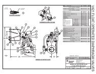
AquaMatic Series A100 Stager Control - Pentair Residential Filtration
AquaMatic Series A100 Stager Control - Pentair Residential Filtration
AquaMatic Series A100 Stager Control - Pentair Residential Filtration
- No tags were found...

You also want an ePaper? Increase the reach of your titles
YUMPU automatically turns print PDFs into web optimized ePapers that Google loves.
<strong>AquaMatic</strong> <strong>Series</strong><strong>A100</strong> <strong>Stager</strong> <strong>Control</strong>sOperation ManualINTRODUCTION TO AQUAMATIC SERIES <strong>A100</strong>STAGER CONTROLSThis series of <strong>AquaMatic</strong> controls combines an electromechanicaltimer with a stager. A stager is a rotary pilot valve with multipleports through which control fluid (air or water) is directed to eitherpressurize or vent <strong>AquaMatic</strong> diaphragm valves. <strong>Control</strong> of a widerange of water treatment systems such as water softeners and filtersis possible. Customer applications are also available.The <strong>A100</strong> series initiates a regeneration based on a time set on thebuilt-in time clock.The control is equipped with a cycle timer which may have from oneto 10 cycles if desired. The maximum cumulative time available fortimed cycles is 102 minutes. The cycle times can be programmedin three minute increments with a minimum cycle length of threeminutes.A variety of stager models may be used with the <strong>A100</strong> series controls.There are three stager designs available:• <strong>Series</strong> 48 brass stager with six ports• <strong>Series</strong> 51 brass stager with eight ports• <strong>Series</strong> 58 PVC stager with sixteen portsThe 48 stager can control typical softener or filter systems as wellas sequential backwash filters. For more complex systems such asnon-standard softeners, twin alternating softeners or filters, the 51 or58 stagers are required.SPECIFICATIONSPower Requirements: 120 VAC/60 Hz/3 Watts220 VAC/50 Hz/3 Watts220 VAC/60 Hz/3 Watts24 VAC/50 Hz/3 Watts<strong>Stager</strong> Port Sizes: All inlet, control, and drain ports have1/8 inch NPT threads (except <strong>Series</strong> 58inlet and drain ports are 1/4 inch NPT<strong>Control</strong> Fluid:Clean Air or Water<strong>Control</strong> Pressure: 125 psi (8.5 bar) maximum<strong>Control</strong> Temperature: 140°F (60°C) (Atmospheric)Enclosure Options: NEMA 1NEMA 4NEMA 4xFGAPPLICATIONSSingle Unit <strong>Control</strong>sTypical Softeners and FiltersTime InitiatedMore Complex Softeners and FiltersTime InitiatedMultiple Unit <strong>Control</strong>sTwin Alternating Softeners and FiltersTime InitiatedSequential FIlters (Backwash Only)Time Initiated2 Unit Sequential Filters(Backwash and Rinse)Time Initiated3 or 4 Unit Sequential Filters(Backwash and Rinse)Time InitiatedFEATURESModel NumberA148A151Model NumberA158TAA148A151A158Standard Features:• NEMA 1 Enclosure• 120 VAC/60 Hz/3 Watts• Homing Feature — If the stager gets out of sequence withthe timer, the homing feature returns the stager to the serviceposition when the timer returns to the service position.• 7 Day Time ClockOptional Features:• NEMA 4 or NEMA 4XFG Enclosure• 220 VAC/50 Hz/3 Watts• 220 VAC/60 Hz/3 Watts• 24 VAC/50 Hz/3 Watts• 6 Day Time Clock• Extra cam and switch option to provide either a dry or poweredcontact closure during any or all cyclesTechnical Support: 1-800-279-9404 (M-F 8:00 am - 5:00 pm CST)1073947 Rev C JA10
3 MIN/PINCYCLE TIME PROGRAMMING<strong>Series</strong> <strong>A100</strong>Each stager is configured with multiple positions. It is important toreview the product document that comes with the stager to determinethe number of positions.NOTE: The number of pins in the UP position on the pinwheel mustequal exactly the number of positions of the stager. Totalregeneration time cannot exceed 102 minutes.1. Remove the thumbscrew from the mounting bracket of the timerand swing the timer to the left.2. Pull up on the first pin (Start Cycle #1) of the pinwheel to mark thestart of the regeneration sequence (Figure 1).3. Use the PIN TIME CHART below, to determine the number of pinsto be left in the DOWN position. The number of pins left in theDOWN position represent the duration of the cycle (each pinequals approximately 3 minutes).4. Pull up the pin that represents start of the next cycle (Start Cycle#2) and repeat step 3 to determine the duration of this cycle.5. Repeat steps 3 and 4 as needed for the remainder of steps in theregeneration process. The last pin that is left in the UP positionwill send the controller back into the Service position.6. Return the timer to the proper mounting position and secure itusing the thumbscrew provided. Ensure that all electrical wiresare located away from the bottom of the timer.Pin Time ChartNumber ofNumber ofTime (Min.)Pins DOWNPins DOWNTime (Min.)0 3 17 541 6 18 572 9 19 603 12 20 634 15 21 665 18 22 696 21 23 727 24 24 758 27 25 789 30 26 8110 33 27 8411 36 28 8712 39 29 9013 42 30 9314 45 31 9615 48 32 9916 51 33 102Start cycle #3Cycle #3 = 9 minReturn to service72846096483602412Service notchPin upPin downFigure 1Cycle #2 = 45 minStart cycle #2Cycle #1 = 15 minStart cycle #1(First pin)2
SETTING <strong>A100</strong> REGENERATION FREQUENCYSetting Days:1. Pull all skipper pins outward away from dial face (see Figure 2).2. Rotate skipper wheel until Day Arrow is aligned with either thecurrent day (for the 7 day wheel) or the number 1 (for the 6 daywheel).3. Depress skipper pin(s) at day(s) a regeneration is desired.6 PM3 PMNOON9 AM6 AMTimer knobSetting Time of Day:1. Grasp timer knob and pull outward.2. Rotate in either direction until actual time of day is aligned withTime Arrow.3. Release timer knob.NOTE: With the time of day properly set, the controller willregenerate at approximately 2:30 AM. If you prefer to have theunit regenerate at an earlier or later time, set the current timeof day accordingly. A label has been provided so that you canapply it to indicate the correct time of day.EXAMPLE: To set the unit to regenerate at 4:30 AM (2 hours later),set the clock 2 hours earlier than the actual current time.Position the label provided on the 24 hour dial whilealigning the mark of the current time with the Time Arrow.Press the label in place.Skipper wheelSkipper pinDay arrowMONTUESUNWEDSATTHUFRIPM3 AMMIDNIGHTSTARTSERVICEDAYFigure 2 <strong>A100</strong> Timer Faceplate24-hour dialTime arrowPointer knobSERIES <strong>A100</strong> STANDARD WIRING DIAGRAMLinePower SupplyNeutral21Timer4MotorMWhiteAquamatic <strong>Stager</strong>3C.UpperTimerSwitchN. O.N.C.Red(Run)Orange(Start)N.O . C.N.C.BlackIndexSwitchMotorMBlackWhite(Neutral)6C. N. O.LowerTimerSwitchN. C .Blue109BlueC. N. O.1st Aux.Switch N.C.(Homing - Shown In Service)VioletYellow785Output During Timer RegenerationFigure 33
REGENERATION INITIATIONS OPTIONS<strong>Series</strong> <strong>A100</strong>:Manual (internal):Automatic:Open enclosure. Depress RED BUTTONand turn pointer knob counterclockwiseto the START position (see Figure 2<strong>A100</strong> Timer Faceplate).Preset day and time.TROUBLESHOOTINGProblemTimer and<strong>Stager</strong> are outof sequence.<strong>Stager</strong> doesnot advanceautomatically.Solution• Check that the number of pins that are in the"UP" position on the timer pinwheel (Figure2 <strong>A100</strong> Timer Faceplate), match EXACTLY thenumber of notches in the stager cam assembly• Make sure that there are no wires coming incontact with the pinwheel assembly.• Manually rotate the stager assembly to the"Service" position. Then, check the operation ofthe timer pinwheel assembly by depressing andthen releasing the micro-switch located on thepinwheel. You can repeat this for each step ofthe regeneration cycle to ensure that the stagerand timer are working properly.• Verify the connections of the "Homing" feature,(If Applicable, See Figure 3)• Manually rotate the stager assemblyapproximately 1/4 inch. The stager motorshould take over the operation and advance thestager to the next step. The "Homing" featurewill return the stager to the "Service" positionautomatically.• Verify that all wiring connections are madecorrectly. (See Figure 3)• Check that the correct voltage and frequencyare being used as specified for the control.5730 North Glen Park Road, Milwaukee, WI 53209Technical Support: 800.279-9404© 2010 <strong>Pentair</strong> <strong>Residential</strong> <strong>Filtration</strong>, LLC 1073947 Rev. C JA10