48ES and 51ES NXT Stager Controller - Pentair Residential Filtration
48ES and 51ES NXT Stager Controller - Pentair Residential Filtration
48ES and 51ES NXT Stager Controller - Pentair Residential Filtration

You also want an ePaper? Increase the reach of your titles
YUMPU automatically turns print PDFs into web optimized ePapers that Google loves.
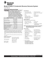
<strong>48ES</strong> <strong>and</strong> <strong>51ES</strong> <strong>NXT</strong> <strong>Stager</strong> <strong>Controller</strong>Service ManualTABLE OF CONTENTS<strong>NXT</strong> STAGER DIMENSIONS..................................................2SYSTEM SPECIFICATIONS <strong>48ES</strong> AND <strong>51ES</strong> SERIES........2SYSTEM DEFINITIONS..........................................................3SYSTEM OPERATION IN SERVICE(SYSTEM 14-DEMAND).........................................................4TIMER DISPLAY FEATURES.................................................5NETWORK/COMMUNICATIONCABLES & CONNECTIONS...................................................5TIMER OPERATION...............................................................6MASTER PROGRAMMING MODE FLOW CHART................7USER PROGRAMMING MODE FLOW CHART.....................9DIAGNOSTIC PROGRAMMING MODE FLOW CHART........9PLUMBING DIAGRAMS.........................................................11SOLENOID USE.....................................................................14STAGER CONTROLLER, <strong>48ES</strong>, NEMA 4 24V/50-60HzASSEMBLY.............................................................................15STAGER CONTROLLER, <strong>51ES</strong>, NEMA 4 24V/50-60HzASSEMBLY.............................................................................16WIRING DIAGRAM 48/<strong>51ES</strong> STAGER CONTROLLER.........17TROUBLESHOOTING............................................................18SERVICE ASSEMBLIES.........................................................19IMPORTANT PLEASE READ:• The information, specifications <strong>and</strong> illustrations in thismanual are based on the latest information availableat the time of printing. The manufacturer reserves theright to make changes at any time without notice.• This manual is intended as a guide for service of thecontroller only. System installation requires informationfrom a number of suppliers not known at the time ofcontrol manufacture. This product should be installedby a plumbing professional.• This product must be installed in compliance with allstate <strong>and</strong> municipal plumbing <strong>and</strong> electrical codes.Permits may be required at the time of installation.• If daytime operating pressure exceeds 80 psi,nighttime pressures may exceed pressure limits. Apressure reducing valve must be installed if pressureexceeds 125 psi.• Do not install the unit where temperatures may dropbelow 32°F (0°C) or above 110°F (43°C).• Do not place the unit in direct sunlight. Black units willabsorb radiant heat increasing internal temperatures.• Do not strike the controller or any of the components.• Warranty of this product extends to manufacturingdefects. Misapplication of this product may resultin failure to properly condition water, or damage toproduct.• A prefilter should be used on installations in which freesolids are present.• Correct <strong>and</strong> constant voltage must be supplied to thecontroller to maintain proper function. 43037 Rev D AU11
<strong>NXT</strong> STAGER DIMENSIONSOptionalSolenoid*10.50 [266.6]5.25 [133.4]1.41 [35.8](6X) 1/8" NPT PORT 60 APARTø 0.733 [18.62 mm]4 places* ø 0.88[22.4 mm]2.45 [62.2]6.42 [163.1]2.06 [52.3]11.13 [282.7]2.75 [69.9] 2.75 [69.9]<strong>48ES</strong> STAGER4.00 [101.6]3.50 [88.9]2.72 [69]2.00 [50.8]1.25 [31.7] 6.00 [152.4](4X) R.16 [4] (4X) .19 [4.8]11.13 [282.7].32 [8.1]8.91 [226.3]1/8" NPT Drain1/8" NPT Filtered Inlet1/8" NPT DrainSYSTEM SPECIFICATIONS <strong>48ES</strong> AND<strong>51ES</strong> SERIESGeneric Meter Guidelines• Open collector output• Pulse rate generated must not exceed 100 pulses persecond (100 Hz), or 6,000 pulses per minute• Support for meter outputs in the range of 1-255 gallons(25.5 m 3 ) for every 1-255 pulsesExample: 35 gallons/100 pulses(=3.5 gallons/10 pulses, = 0.35 gallons/1 pulse)• Meter must operate at 5 VDCElectrical Rating• 24 VAC Transformers115 VAC ±20% input, 24 VAC output w/40 VA (maintaininput voltage in this range)230 VAC ±20% input, 24 VAC output w/108 VA (maintaininput voltage in this range)• Max Rated Power 15WHumidity• 95% RH, non-condensingTemperature• Maximum control fluid temperature 140°F (60°C)• Operate where ambient temperatures are above 32°F<strong>and</strong> below 110°FPressure• Maximum control fluid pressure 125 psi (8.5 bar)• Control fluid can be either water or air <strong>and</strong> must be equalto or greater than system pressure.1/8" NPT Filtered Inlet1.75 [44.4]*(8X) 1/8" NPT - 45 APARTø 0.733 [18.62 mm]4 places1/8" NPT Drain*ø 0.88[22.4 mm]<strong>51ES</strong> STAGER*NOTE: Drill as required. These holeswill only be drilled at factory ifrequired.Figure 12 • <strong>NXT</strong> <strong>Stager</strong> <strong>Controller</strong> AU11
SYSTEM OPERATION IN SERVICE(SYSTEM 14-DEMAND)The system operates as part of a multi-tank regenerationsystem. This example applies to either a 2, 3 or 4 tank system.Each tank in the system will have an active flow meter input,even in St<strong>and</strong>by.The number of tanks In Service depends on the flow rate.Examples of a Four-Unit System:1. One Tank is In Service at all times (the "primary tank").5. The third tank returns to St<strong>and</strong>by as dem<strong>and</strong> decreasespast the second trip point.1 2 3 41 2 3 4In Service(Primary Tank)St<strong>and</strong>by2. The total flow rate to the primary tank increased past thefirst trip point programmed rate. The flow stayed pastthe trip point delayed time. The next tank (least volumeremaining) changes from St<strong>and</strong>by to In Service. This thensplits the total flow between two meters.First Trip Point(Primary Valve)1 2 3 4In ServiceTotal Flow SplitBetween Two MetersSt<strong>and</strong>by3. The flow rate dem<strong>and</strong> decreased below the first trip point.The tank returns to St<strong>and</strong>by.Flow Split BetweenTwo MetersSt<strong>and</strong>by6. Tanks return to St<strong>and</strong>by due to decreased total flow rate<strong>and</strong> trip points programmed. The tank with the mostremaining volume will be the first to go into St<strong>and</strong>by.1 2 3 4Full Capacity4th in St<strong>and</strong>by(Primary Valve)3/4 Capacity3rd in St<strong>and</strong>by1/2 Capacity2nd in St<strong>and</strong>by1/4 Capacity1st in St<strong>and</strong>by7. The primary tank regenerates. The next tank with the leastremaining volume becomes the new primary tank. The tankwith the next least volume remaining will be the first trippoint programmed rate. Tanks continue operating in thisorder.System Operation in Regeneration:1 2 3 4Flow Rate Dem<strong>and</strong>Below First Trip Point(Primary Valve)1 2 3 4St<strong>and</strong>by4. Total flow rate dem<strong>and</strong> increased past a second trip pointprogrammed rate. The second <strong>and</strong> third tank (least volumeremaining) changes from St<strong>and</strong>by to In Service. The totalflow is split between the three meters.Full Capacity4th in St<strong>and</strong>by3/4 Capacity3rd in St<strong>and</strong>by1/2 CapacityFirst Trip PointProgrammed Rate1/4 CapacityNew Primary TankIf two tanks are In Service <strong>and</strong> both reachVolume Remaining = 0, the other two tanks will shift fromSt<strong>and</strong>by to In Service. The lead tank withVolume Remaining = 0 will start Regeneration. The secondtank with Volume Remaining = 0 will enter St<strong>and</strong>by. If flowincreases past the trip point a third tank needs to enter InService. The tank in St<strong>and</strong>by with Volume Remaining = 0 willshift into In Service to maintain a steady flow. Operating forextended periods in this mode may degrade the water quality.1 2 3 4Flow Split BetweenThree MetersSt<strong>and</strong>by4 • <strong>NXT</strong> <strong>Stager</strong> <strong>Controller</strong> AU11
TIMER DISPLAY FEATURESValve State(SBY, SRV, INI, LCK)ValveAddressSystemNumberFlowIndicatorTimeof DayDisplay ScreenTime of Day alternateswith Error ScreenExample: Valve #, VolumeRemaining, ErrorsVolume RemainingDiagnostic ButtonView Flow Rate, Peak FlowRate, Totalizer, HoursBetween Last TwoRegenerations, Hours SinceLast Regeneration, AdjustableVolume Remaining, ValvePosition, Send & ReceiveErrors, Software VersionExtra Cycle ButtonCycle Valve inRegeneration/CycleProgramming StepsShift ButtonAdjusts Values to the LeftUp ButtonAdjusts Values UpNETWORK/COMMUNICATION CABLES& CONNECTIONSUse a CAT5 Network/Communication cable.Connect the network/communication cable to either port beforeprogramming.The maximum cable length between timers is 100 feet.Connect units together from one communication port to thenext communication port. The order is not important.GroundLockRegen Communication PortsStatus LEDValve StateFigure 1Down ButtonAdjusts Values DownINI (Initializing) - INI will display on the screen for 30 to45 seconds when initializing after a power failure reset orprogramming.RGQ (Regeneration Queued) -RGQ indicates that the reservehas been entered in a delayed system <strong>and</strong> regeneration hasbeen queued. When in the main screen, press the Extra Cyclebutton to toggle service (SRV) with RGQ.Service (SRV) - SRV will display when the unit is In Service.LCK (Lock) - Lock will be displayed when contact closure isapplied across the interlock terminals on the circuit board. Seethe “Network/Communication Cables & Connections” section ofthis manual.LED Status LightsBlue LED - Illuminates while the unit is In Service <strong>and</strong> noerrors exist. The unit will always be In Service unless aregeneration trigger has occurred (green LED light will bedisplayed). A blinking blue light indicates the timer is In Service,<strong>and</strong> queued for regeneration.Green LED - Illuminates when the unit is in Regenerationmode. A blinking green light indicates the timer is in St<strong>and</strong>by,<strong>and</strong> not in Regeneration.Red LED- Illuminates when there is an error.Flow IndicatorA rotating line (appearing as a rotating star shape) will displayon the screen when flow is going through the meter.Figure 2 Current <strong>NXT</strong> Circuit Board<strong>NXT</strong> <strong>Stager</strong> <strong>Controller</strong> AU11 • 5
TRIP DELAY 1:30 SECONDSMASTER PROGRAMMING MODE FLOWNOTE: Display will only appear on the master timer <strong>and</strong> it must beprogrammed as valve position #1. Use the Shift button to move one spaceCHART to the continuedleft.NOTE: This screen will only display for System 14.CYCLE 4 OFFCYCLE 4 00:12:00CYCLE 5 OFFExample:Off (Default 48-00 <strong>Stager</strong>)Example: Refill00:12:00 (Default 51-09 <strong>Stager</strong>)(Hours:Minutes:Seconds)Example:Off (Default 51-09 <strong>Stager</strong>)TRIP POINT 2:gpm2 to 998 gpm1 to 3997 LpmNOTE: Display will only appear on the master timer <strong>and</strong> it must beprogrammed as valve position #1. System size must be 3 or 4 to appear. Usethe Shift button to move one space to the left.NOTE: This screen will only display for System 14.TRIP DELAY 2:30 SECONDSNOTE: Display will only appear on the master timer <strong>and</strong> it must beprogrammed as valve position #1. System size must be 3 or 4 to appear. Usethe Shift button to move one space to the left.NOTE: This screen will only display for System 14.TRIP POINT 3:gpm3 to 999 gpm1 to 3997 LpmNOTE: Display will only appear on the master timer <strong>and</strong> it must beprogrammed as valve position #1. System size must be 4 to appear. Use theShift button to move one space to the left.NOTE: This screen will only display for System 14.TRIP DELAY 3:30 SECONDSNOTE: Display will only appear on the master timer <strong>and</strong> it must beprogrammed as valve position #1. System size must be 4 to appear. Use theShift button to move one space to the left.NOTE: This screen will only display for System 14.REGENERATION DAYOVERRIDE:OFFREGENERATION DAYOVERRIDE:01 DAYSExample:Off (Default for Meter)On (Default for Time Clock)Example:1 DayOptions: Off (Default for Meter) or On (Default for Time Clock)Range: 1 to 99 DaysREGENERATIONTIME: 02:00AMExample:2:00 A.M. (Default)Options: A.M. (U.S. Format)HR (Metric Format)NOTE: Regeneration time will not appear unless Regeneration Day Overrideis on.NOTE: This screen will only display when cycle 4 is not OFF.AUXILIARY RELAY:DISABLEDOptions: EnabledDisabled (Default)AUX RELAY OUTPUTSTART 1 00:00:00Example:Auxiliary Relay is DisabledExample:Auxiliary Relay Output Start 1 at0 hours, 0 minutes, & 0 secondsRange: 00:00:00 to 18:00:00NOTE: Only displayed if Auxiliary Relay is enabled in previous screen.Auxiliary Relay will only display if Chemical Pump is OFF for SystemTypes 6 & 7.AUX RELAY OUTPUTEND 1 00:00:00Range: 00:00:00 to 18:00:00CHEMICAL PUMP:DISABLEDExample:Auxiliary Relay Output End 1 at0 hours, 0 minutes, & 0 secondsExample:Chemical Pump is DisabledOptions: EnabledDisabled (Default)NOTE: This screen will only display on the lead unit for System Types 6 & 7.For all other System Types, it will display for all units.CPO AUX RELAYVOLUME: 000 9Range:1 to 999 gallons in U.S. Format1 to 9999 L in Metric FormatCPO AUX RELAYTIME: 00:00:00Range: 00:00:00 to 02:00:00FLOW METER:1.0 PADDLEExample:Energize Chemical Pump relay every 50 gals (50)Energize Chemical Pump relay every 200 L (200)Example:Each time chemical pump relay is on, run for30 seconds (00:00:30)Example:1.0 Paddle Flow MeterOptions: 1.0 Paddle1.0 Turbine1.5 Paddle1.5 Turbine2.0 Paddle3.0 PaddleGenericNOTE: Default flow meter type is based on the valve type. This screen willonly display on the lead unit for System Types 6 & 7. All other system typesit will display for all units.MAXIMUM FLOWRATE: 0000 gpmExample:Maximum Flow Rate of 0 gpmCYCLE 1 00:10:00Example: Backwash00:10:00 (Default 48-00 <strong>Stager</strong> & 51-09 <strong>Stager</strong>)(Hours:Minutes:Seconds)Range: 20 - 2000 gpm (U.S. Format)20 - 2000 Lpm (Metric Format)NOTE: Only displayed if “Generic” is chosen for the flow meter.CYCLE 2 01:00:00 Example: Brine01:00:00 (Default 48-00 <strong>Stager</strong> & 51-09 <strong>Stager</strong>)(Hours:Minutes:Seconds)Options: 01:00:00 for Conditioner for the 48-00 <strong>Stager</strong> & 51-09 <strong>Stager</strong> (Default)00:00:00 for Filter for the 48-00 <strong>Stager</strong>CYCLE 3 00:10:00Example: Fast Rinse00:10:00 (Default 48-00 <strong>Stager</strong> & 51-09 <strong>Stager</strong>)(Hours:Minutes:Seconds)ADD 01 GALLONSEVERY 001 PULSESExample:Add 1 Gallon for Each Pulse in U.S. FormatOptions: Gallons (U.S. Format)Liters (Metric Format)Range: 1 - 99 Gallons (U.S. Format)0.1 - 09.9 L (Metric Format)Pulses: 1 - 99NOTE: Only displayed if “Generic” is chosen for the flow meter.CYCLE 4 OFFCYCLE 4 00:12:008 • <strong>NXT</strong> <strong>Stager</strong> <strong>Controller</strong> AU11CYCLE 5 OFFExample:Off (Default 48-00 <strong>Stager</strong>)Example: Refill00:12:00 (Default 51-09 <strong>Stager</strong>)(Hours:Minutes:Seconds)Example:Off (Default 51-09 <strong>Stager</strong>)PROGRAMMING UNITPLEASE WAIT...Example:Master Programming Mode is Exiting
USER PROGRAMMING MODE FLOWCHARTEntering User Programming ModeHold the Up <strong>and</strong> Down buttons for 5 seconds.FEED WATERHARDNESS:gpgDIAGNOSTIC PROGRAMMING MODEFLOW CHARTEntering Diagnostic Programming Mode1. Push <strong>and</strong> release the "D" button.2. Press the Extra Cycle button once per display until alldisplays are viewed <strong>and</strong> Normal Display is resumed.3. Push <strong>and</strong> release the"D" button at anytime duringdiagnostic mode <strong>and</strong> the timer will exit the mode.4. Depending on the current controller programming, certaindisplays may not be able to be viewed or set.Options: U.S. FormatMetric Format[gpg][mgL]REGENERATION DAYOVERRIDE: OFFOptions: U.S. FormatMetric Format[OFF] = default[OFF] = defaultCURRENT FLOWRATE:0 gpmExplaination: Flow rate at this time.PEAK FLOW RATE:0 gpmExplaination: Peak flow since last regeneration.REGENERATION DAYOVERRIDE:99 DAYSTOTALIZER:130 gExplaination: Gallons at the outlet since installation.REGENERATIONTIME: 02:00AMOptions: U.S. FormatMetric Format[02:00AM] = default[02:00] = defaultLAST TWO REGENS:0 HOURSExplaination: Hours between the last regeneration <strong>and</strong> the one before it.LAST REGEN0 HOURSExplaination: Hours since last regeneration.VOLUME REMAIN:1000 gExplaination: Volume remaining; can be adjusted.VALVE ADDRESS#2Explaination: <strong>Controller</strong> unit number.VERSION:X.XXExplaination: Installed software level of the controller in use.<strong>NXT</strong> <strong>Stager</strong> <strong>Controller</strong> AU11 • 9
<strong>NXT</strong> Multi LanguageProgramming Parameters <strong>and</strong> RangesSystem Type4TimeClockValve Address 1 2 3 4 1 2 3 4 1 2 1 2 3 4 1 2 3 4Select Language x x x x x x x x x x x x x x x x x x x x xSystem Size x x x x xRegen Type x x x x x x x x x x x x x x x x x x x x xValve Type x x x x x x x x x x x x x x x x x x x x xRegenerant Flow x x x x x x x x x x x x x x x x x x x x xRemote Signal Start x x x x x x x x x x x x xGallons LitersDisplay Format x x x x x x x x x x x x x x x x x x x x x US - Gallons EU - Metric-LitersUnit Capacity x x x x x x x x x x x x x x x x x 1 - 9900000 Grains 1 - 198000 gCaCO3Capacity Safety Factor x x x x x x x x x x x x x x x x x0- 50%Feed Water Hardness x x x x x x x x x x x x x x x x x 1 - 199 Grains/Gallons 1 - 1999 mgLTrip Point 1 x 0 - 997gpm 0 - 3997 LpmTrip Delay 1 x 30 - 99 Seconds 30 - 99 SecondsTrip Point 2 x Trip Point 1 + 1 - 998 gpm Trip Point 1 + 1 - 3998 LpmTrip Delay 2 x 30 - 99 Seconds 30 - 99 SecondsTrip Point 3 x Trip Point 2 + 1 - 999 gpm Trip Point 2 + 1 - 3999 LpmTrip Delay 3 x 30 - 99 Seconds 30 - 99 SecondsRegeneration Day Override x x x x x x x x x x x x x x x x xOff, 1 - 99Regeneration Time x o o o o o o o o o o o o o o o o o 12:00 a.m. - 11:59 p.m. 00:00 - 23:59 HourCycle 1 x x x x x x x x x x x x x x x x x x x x xCycle 2 x x x x x x x x x x x x x x x x x x x x xCycle 3 x x x x x x x x x x x x x x x x x x x x xCycle 4 x x x x x x x x x x x x x x x x x x x x xCycle 5 x x x x x x x x x x x x x x x x x x x x xAuxiliary Relay x x x x x x x u x x x u x x x x x x x x xAux Relay Output Start c c c c c c c c c c c c c c c c c c c c cAux Relay Output End c c c c c c c c c c c c c c c c c c c c cChemical Pump x x x x x x u u x x x x x x x xCPO Aux Relay Volume c c c c c c c c c c c c c c c c 1 - 999 gallons 0001 - 9999 LitersCPO Aux Relay Time c c c c c c c c c c c c c c c c 00:00:01 - 02:00:00 00:00:01 - 02:00:00Flow Meter x x x x x x x x x x x x x x x x 1" 1.5" Paddle or Turbine, 2" Paddle, 3" Paddle, GenericGeneric x x x x x x x x x x x x x x x xMaximum Flow Rate a a a a a a a a a a a a a a a a 20 - 2000 GPM 20 - 2000 LPMAdd _ _ _ Gallons or Liters a a a a a a a a a a a a a a a a 1 - 255 Gallons 001 - 255 LitersEvery _ _ _ Pulses a a a a a a a a a a a a a a a a 1 - 255 1 - 255Notes o -4MeteredImmediate4MeteredDelayed5Interlock6Series7AlternatingRegeneration Time will only be viewed if Regeneration Day Override is used.9Alternating14Dem<strong>and</strong>RecallProgramming Parameter Ranges1 thru 4English, Espanol, Portugues, Deutsch, Francais1 thru 4Time Clock, Metered Delayed, Metered Immediate2750, 2850, 2900, 3150, 3900, <strong>Stager</strong>Downflow, Upflow, Upflow Fill FirstOff, 00:00:01 - 01:39:0000:00:00 - 04:00:00Off, 00:00:00 - 04:00:00Off, 00:00:00 - 04:00:00Off, 00:00:00 - 04:00:00Off, 00:00:00 - 04:00:00Enabled, Disabled00:00:01 to Total Regeneration Time - 1Start Time + 1 to Total Regeneration TimeEnabled, Disabledu -If Auxiliary Relay is Enabled then Chemical Pump Relay will not be viewed or if Chemical Pump Relay is Enabled then Auxiliary Relay will not be viewed.c -a -All Relay Output parameters programming will be viewed if Enabled.If Generic Flow Meter is chosen, then programming parameters will be viewed.10 • <strong>NXT</strong> <strong>Stager</strong> <strong>Controller</strong> AU11
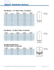
<strong>Stager</strong> Operation<strong>Stager</strong>s are motor driven, rotary multi-port valves used tocontrol a set of valves in a predefined sequence. They functionby internally connecting inlet pressure to a defined set ofcontrol ports <strong>and</strong> allowing other control ports be vented througha drain. Control ports are used to open <strong>and</strong> close valves in apreset sequence. As the stager advances to various positions,different valves are open <strong>and</strong> closed in a system. The controlport pressure <strong>and</strong> vent sequence is preset at the factory <strong>and</strong>cannot be field altered.<strong>Stager</strong> Installation1. Connect a constant pressure water or air source to the 1/8"NPT stager inlet. Control fluid pressure must be equal to orgreater than system pressure. To ensure long trouble freeoperation, a 100 micron filter in the control pressure line isrecommended.2. <strong>Stager</strong> drain port should be left open or discharged tounrestricted or open drain. DO NOT plug or restrict drainport.3. Connect the 1/8" NPT control ports to appropriate valves.Refer to tubing schematic provided in the PlumbingDiagrams section of this manual. Tubing inside diametershould be 1/8" or larger.Inverted Type <strong>Stager</strong>s<strong>Stager</strong>s that are ordered inverted would be used on systemswith all normally closed valves. Inverted <strong>Stager</strong>s send pressuresignals to open valves <strong>and</strong> vent signals to close valves.PLUMBING DIAGRAMS4 Position Softener (48-00 <strong>Stager</strong>)Optional HardWater Bypass ValveDrain Line FlowControl not shownBANote A: All valves normally open except optional valve 2A.Note B: Inverted <strong>Stager</strong> types will have these ports pressurized.Inverted <strong>Stager</strong> to be used with all valves normally closed exceptoptional valve 2A.<strong>NXT</strong> <strong>Stager</strong> <strong>Controller</strong> AU11 • 11
PLUMBING DIAGRAMS continued4 Position Filter (48-00 <strong>Stager</strong>)5 Position Softener w/Timed Brine Refill(51-09 <strong>Stager</strong>)CustomerSupplied ValveOptional HardWater Bypass ValveOptional HardWater Bypass ValveDrain Line FlowControl not shown4 POSITION FILTERDrain Line FlowControl not shownInstaller to plug (withPN1071903)for filter operationPlugs installedat factoryBABACNote A: All valves normally open except optional valve 2A.Note B: Inverted <strong>Stager</strong> types will have these ports pressurized.Inverted <strong>Stager</strong> to be used with all valves normally closed exceptoptional valve 2A.Note A: All valves normally open except optional valve 2A.Note B: Inverted <strong>Stager</strong> types will have these ports pressurized.Inverted <strong>Stager</strong> to be used with all valves normally closed exceptoptional valve 2A.Note C: Program Cycle 2 time to 00:00:00 for filter operation.12 • <strong>NXT</strong> <strong>Stager</strong> <strong>Controller</strong> AU11
PLUMBING DIAGRAMS continuedMultiple Tank 4 Position Softener (48-00 <strong>Stager</strong>)EJECTOR5A3A5B3BRAW WATERBRINEINLET1A1BTo Additional TanksAs Required4A4B2A6A2B6BSERVICEUNIT ANOTE: All valves normally open, pressure to close.NOTE: Valve 2 for each tank is controlled by solenoid forsystem 7, 9, 14DRAINUNIT BDRAIN LINE FLOWCONTROL NOT SHOWNMultiple Tank 5 Position Softener (51-09 <strong>Stager</strong>)Customer SuppliedCheck ValveCustomer SuppliedCheck ValveTo Brine TankEjector3ATo Brine TankEjector3B5A5BINLET7A1A4A7B1B4BTo Additional TanksAs RequiredTo Brine Refill2A6ATo Brine Refill2B6BSERVICEUNIT ANOTE: All valves normally open, pressure to close.NOTE: Valve 2 for each tank is controlled by solenoid forsystem 7, 9, 14DRAINUNIT BDRAIN LINE FLOWCONTROL NOT SHOWN<strong>NXT</strong> <strong>Stager</strong> <strong>Controller</strong> AU11 • 13
SOLENOID USESolenoids only required for Systems 7, 9 <strong>and</strong> 14Series 48-00/51-09 <strong>Stager</strong>SolenoidValveDrain3Installer toPlug Port 2Inlet Pressure1 2232311FlowFlowSolenoid EnergizedSolenoid De-energizedEnergized To CloseThe <strong>NXT</strong> <strong>Stager</strong> control can operate an optional 24 VACsolenoid to control when a tank is off line. This solenoid iselectrically connected to the "lower drive" connection on thecircuit board, <strong>and</strong> control pressure is run through the solenoidto the service outlet diaphragm valve.The solenoid installed at the factory is a universal type. It isplumbed in an energize to close configuration when serviceoutlet valve is normally open.When a tank enters Regeneration or St<strong>and</strong>by the solenoid isenergized. Pressure from solenoid port 1 passes to port 2. Thediaphragm valve #2 will close.When a tank enters In Service the solenoid is de-energized.The inlet pressure to solenoid port 2 is stopped. Thediaphragm valve is vented through solenoid port 2 to port 3(drain). The valve #2 opens.Inverted <strong>Stager</strong>s Only - Energize to OpenIf the service outlet vavle is normally closed, connect constantpressure source to solenoid port 3. Connect solenoid port 2 toservice outlet valve. Solenoid port 1 is drain.14 • <strong>NXT</strong> <strong>Stager</strong> <strong>Controller</strong> AU11
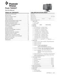
STAGER CONTROLLER, <strong>48ES</strong>, NEMA 424V/50-60Hz ASSEMBLY4139384731 34352650AUX 1 (RED)CYCLE (WHITE)HOFFMAN PARTS BAGSCALE 1:430 3332471334443423724834237162722214951242528294536ISO FRONT VIEWSCALE 1:44017518194611KIT BR61764SCALE 1:46 89151412TO METERNOT CONNECTED20101213BOTTOM DETAIL VIEWSCALE 1:261803 Rev DItem No. QTY Part No. Description1 .................. 1 ......... 43001 ................... Motor, 24V, 50/60Hz, 5/8 RPM2 .................. 1 ......... 1070436 ............... Plate, Motor MTG, <strong>Stager</strong>s3 .................. 6 ......... 1075746 ............... Screw, 6-32 x 1/4", Phil4 .................. 4 ......... 1072371 ............... Screw, 6-32 x .375, RD.HD, SS5 .................. 1 ......... 1075737 ............... Gasket, <strong>Stager</strong> MTG, 486 .................. 1 ......... 1071667 ............... O-ring, 2-010, Nitrile7 .................. 1 ......... 1075454* .............. Thumb Wheel, Molded8 .................. 1 ......... 1074074 ............... Washer, 302, SS9 .................. 1 ......... 1070448 ............... Shaft, Stem Assy, 48 Series10 ................ 1 ......... 1074784 ............... Backplate, 48-00, Brass11 ................ 1 ......... 1074793 ............... Bonnet, 48, Brass12 ................ 1 ......... 1074825 ............... Inlet Strainer, Assy13 ................ 3 ......... 1075759 ............... Screw, Pan Head, 6-32 x .88"14 ................ 1 ......... 1076234 ............... Spring, Wave, 17-7 SS, 48 STGR15 ................ 1 ......... 1074845 ............... Stemplate, 48, -0016 ................ 1 ......... 1076245* .............. Cam, Cycle, Machined17 ................ 1 ......... 1070437 ............... Plate, Bottom MTG, <strong>Stager</strong>18 ................ 2 ......... 1075499 ............... Switch, Micro19 ................ 1 ......... 1075455 ............... Switch Spacer, Insulator20 ................ 1 ......... 1084171 ............... Gasket, Backplate, 48 Nitrile21 ................ 2 ......... 1073593 ............... Washer, Lock, Internal, #4, SS22 ................ 2 ......... 1075757 ............... Machine Screw, 4-40 x 1.00, SS if 2switches2 ......... 1072389 ............... Screw, 4-40 x 1-3/8" if 3 switches23 ................ 1 ......... 1075453* .............. Cam, Auxiliary, Blank24 ................ 2 ......... 3014200 ............... Screw, Slotted HX HD, 10-3225 ................ 2 ......... 1078992 ............... Washer, Lock, Internal, #10, SS26 ................ 1 ......... 14202-01 .............. Screw, Hex Washer #8-32 x 5/1627 ................ 1 ......... 43077-00 .............. Label, Dial, STGR, 2 3/8 x 7/828 ................ 2 ......... 17967-01 .............. Nut, Liquid Tight, HeyCo 316929 ................ 2 ......... 17967-02 .............. Fitting, Liquid Tight, Black30 ................ 1 ......... 1075538 ............... Terminal Block, 1031 ................ 2 ......... 1072369 ............... Screw, Pan HD, 4-40 x 5/8, SS32 ................ 1 ......... 1076219 ............... Label, Ground, .75 Dia.Item No. QTY Part No. Description33 ................ 1 ......... 1073732 ............... Label, Terminal Strip, 1-1034 ................ 1 ......... 43094-01 .............. Enclosure, <strong>48ES</strong>, NEMA 435 ................ 1 ......... 43093 ................... Panel, A10P, 8" x 6" Modified36 ................ 1 ......... 43046* .................. Keypad Label Assy, XT, NEMA 437 ................ 1 ......... 1070649 ............... Solenoid, N1, 24/6038 ................ 4 ......... 42827-04 .............. St<strong>and</strong>-off, Plastic, .625"39 ................ 1 ......... 42753U* ............... Circuit Board, XT, ML40 ................ 4 ......... 43092 ................... Screw, FLT HD, #6-20, TYP-B41 ................ 1 ......... 40941 ................... Harness, Upper Drive42 ................ 1 ......... 43090 ................... Washer, Sealing, Conduit, 1/2"43 ................ 1 ......... 43140 ................... Fitting, NPT 1/2, Conduit44 ................ 1 ......... 43141 ................... Washer, Lock, 7/8, INT Tooth45 ................ 1 ......... 61764 ................... Cable Assy, COM, CAT 5E, NEMA 446 ................. 1 ..........19121-09 ...............Meter Cable Assy, NT, 99.5"47 ................. 4 ..........1081780 ................Mount, Cable Tie, 4-Way48 ................. 1 ..........1072379 ................Screw, 10-32 x 5/8", RND HD, SS49 ................. 1 ..........1071660 ................Nut, Hex, 10-32, KEPS50 ................. 1 ..........43177 ....................Washer, Lock, #8, INT, 18-8 SS51 ................. 1 ..........1071648 ................NutNot Shown1 ......... 61500-48/51LNE .. Line Drawing9 ......... 1073701 ............... Tie, Cable, HeyCo VNT#4-182 ......... 1073702 ............... Wire Tie3 ......... 1073955 ............... Terminal, Ring, #10, 16-14 GA1 ......... 1073875 ............... Wire, Black, 18 AWG1 ......... 1073880 ............... Wire, White, 18 AWG1 ......... 1073874 ............... Wire, Green, 14 AWG1 ......... 43163 ................... Literature, 3214 <strong>NXT</strong> <strong>Stager</strong>,S/M1 ......... 43012 ................... Wiring Diagram, 48/<strong>51ES</strong>1 ......... 61784 ................... Service Kit, 48/51, Timer1 ......... 61783 ................... Service Kit, 48/51, Solenoid1 ......... 1071903 ............... 1/8" NPT Pipe Plug Brass*Only sold as Service Assembly<strong>NXT</strong> <strong>Stager</strong> <strong>Controller</strong> AU11 • 15
BOTTOM DETAIL VIEWSTAGER CONTROLLER, <strong>51ES</strong>, NEMA 424V/50-60Hz ASSEMBLY30AUX 1 (Red)29362139272420 232251CYCLE (White)HOFFMAN PARTS BAGSCALE 1:41636133233312372635131738521415181925ISO FRONT VIEWSCALE 1:4288412119506103534KIT BR61764SCALE 1:443404148454446427424761804 Rev DItem No. QTY Part No. Description1 .................. 1 ......... 43001 ................... Motor, 24V, 50/60Hz, 5/8 RPM2 .................. 1 ......... 1070436 ............... Plate, Motor MTG, <strong>Stager</strong>s3 .................. 6 ......... 1075746 ............... Screw, 6-32 x 1/4", Phil4 .................. 2 ......... 1072371 ............... Screw, 6-32 x .375, RD.HD, SS5 .................. 1 ......... 1075454* .............. Thumb Wheel, Molded6 .................. 1 ......... 1075674 ............... Gasket, <strong>Stager</strong> MTG, 51, 967 .................. 1 ......... 1074825 ............... Inlet Strainer, Assy8 .................. 1 ......... 1076243* .............. Cam, Cycle, Machined9 .................. 2 ......... 1075499 ............... Switch, Micro10 ................ 1 ......... 1075455 ............... Switch Spacer, Insulator11 ................ 2 ......... 1073593 ............... Washer, Lock, Internal, #4, SS12 ................ 2 ......... 1075757 ............... Machine Screw, 4-40 x 1.00, SS13 ................ 1 ......... 1075453* .............. Cam, Auxiliary, Blank14 ................ 2 ......... 3014200 ............... Screw, Slotted HX HD, 10-3215 ................ 2 ......... 1078992 ............... Washer, Lock, Internal, #10, SS16 ................ 1 ......... 14202-01 .............. Screw, Hex Washer #8-32 x 5/1617 ................ 1 ......... 43078-09 .............. Label, Dial, STGR, 2 3/8 x 7/818 ................ 2 ......... 17967-01 .............. Nut, Liquid Tight, HeyCo 316919 ................ 2 ......... 17967-02 .............. Fitting, Liquid Tight, Black20 ................ 1 ......... 1075538 ............... Terminal Block, 1021 ................ 2 ......... 1072369 ............... Screw, Pan HD, 4-40 x 5/8, SS if 2switches2 ......... 1072389 ............... Screw, 4-40 x 1-3/8" if 3 switches22 ................ 1 ......... 1076219 ............... Label, Ground, .75 Dia.23 ................ 1 ......... 1073732 ............... Label, Terminal Strip, 1-1024 ................ 1 ......... 43093 ................... Panel, A10P, 8" x 6" Modified25 ................ 1 ......... 43046* .................. Keypad Label Assy, ST, NEMA 426 ................ 1 ......... 1070649 ............... Solenoid, N1, 24/6027 ................ 1 ......... 42753U* ............... Circuit Board, XT, ML28 ................ 4 ......... 43092 ................... Screw, FLT HD, #6-20, TYP-B29 ................ 4 ......... 42827-04 .............. St<strong>and</strong>-off, Plastic, .625"30 ................ 1 ......... 40941 ................... Harness, Upper Drive31 ................ 1 ......... 43090 ................... Washer, Sealing, Conduit, 1/2"32 ................ 1 ......... 43141 ................... Washer, Lock, 7/8, INT Tooth49SCALE 1:2Item No. QTY Part No. Description33 ................ 1 ......... 43140 ................... Fitting, NPT 1/2, Conduit34 ................ 1 ......... 61764 ................... Cable Assy, COM, CAT 5E, NEMA 435 ................ 1 ..........19121-09 ...............Meter Cable ASSY, NT, 99.5"36 ................ 4 ..........1081780 ................Mount, Cable Tie, 4-Way37 ................ 1 ..........1072379 ................Screw, 10-32 x 5/8", RND HD, SS38 ................ 1 ..........1071660 ................Nut, Hex, 10-32, KEPS39 ................ 1 ......... 43094-02 .............. Enclosure, <strong>51ES</strong>, NEMA 440 ................ 1 ......... 1075241 ............... Washer, 302, SS41 ................ 1 ......... 1070438 ............... Shaft, Stem Assy, 51 Series42 ................ 2 ......... 1071903 ............... Male Pipe Plugs43 ................ 1 ......... 1074883 ............... Bonnet, 51, Brass44 ................ 1 ......... 1075647* .............. Stemplate, 96, Alpha45 ................ 1 ......... 1075242 ............... Spring, Compression46 ................. 1 ..........1084172 ................Gasket, Backplate, 51 & 96 STGRS47 ................. 1 ..........1074866* ...............Backplate, D.V. Nest48 ................. 1 ..........1071716 ................O-ring, EP, ORE-01149 ................. 4 ..........1075760 ................Screw, Machine, #6-32 x 1 1/850 ................. 1 ..........1077824 ................MTG Plate, BTM, STGR, <strong>51ES</strong>51 ................. 1 ..........43177 ....................Washer, Lock, #8, INT, 18-8 SS52 ................. 1 ..........1071648 ................NutNot Shown1 ......... 61500-48/51LNE .. Line Drawing9 ......... 1073701 ............... Tie, Cable, HeyCo VNT#4-182 ......... 1073702 ............... Wire Tie3 ......... 1073955 ............... Terminal, Ring, #10, 16-14 GA1 ......... 1073875 ............... Wire, Black, 18 AWG1 ......... 1073880 ............... Wire, White, 18 AWG1 ......... 1073874 ............... Wire, Green, 14 AWG1 ......... 43163 ................... Literature, 3214 <strong>NXT</strong> <strong>Stager</strong>,S/M1 ......... 43012 ................... Wiring Diagram, 48/<strong>51ES</strong>1 ......... 61784 ................... Service Kit, 48/51, Timer1 ......... 61783 ................... Service Kit, 48/51, Solenoid*Only sold as Service Assembly16 • <strong>NXT</strong> <strong>Stager</strong> <strong>Controller</strong> AU11
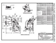
WIRING DIAGRAM 48/<strong>51ES</strong> STAGERCONTROLLEROPTIONAL MOTOR/PUMP ON DURING REGENERATIONOR CPO DEVICE ON DURING SERVICE (N.O. OUTPUT)SWITCHED HOTM 1OPTIONAL INTERLOCKSWITCH (N.O.)NEUTRAL24VAC/3A MAX. RESISTIVE30VDC/3A MAX. RESISTIVEUNSWITCHED HOTOPTIONAL REMOTESIGNAL STARTSWITCH (N.O.)-CLOSED CONTACT PREVENTS REGENERATION-INPUT SIDE PULLED UP TO 32 VDC-CLOSED CONTACT INITIATES REGENERATION IF OPTION ENABLED-INPUT SIDE PULLED UP TO 32 VDCGREEN/YELLOWOPTIONAL SOLENOID VALVE ENERGIZEDDURING REGENERATION OR STANDBY(P6 OUTPUT - 24VAC 50/60Hz, 1.0 A,MAX.)BLACKBLACKSWITCHED HOTNEUTRAL12345678910SW 3SW 2SW 1CCCN.O.N.C.N.O.N.C.N.O.N.C.BLACKORANGEBLACKPURPLEPURPLEORANGEBLACKWT/BLKYELLOWBLACKWHITEBLACKGREENBLACKBROWNBLUEREDGREEN/YELLOWBLUEBLUEGREEN/YELLOWBLACKGREEN/YELLOWLOCK OUTREMOTE STARTGNDAUXCAN1 CAN2F1LOWPER DRIVEWHITES1UPPER DRIVE24V ACMETEROPTIONAL FLOW METER-NOT REQUIRED FOR TIME CLOCK OR REMOTE SINGALSTART REGENERATION APPLICATIONS.BLACKBLACKWHITEGREEN/YELLOWGROUNDSCREWBLACKWHITEFMGROUNDLUGBR4300124V/50/60, 4 WATT OPTIONALAUX CAM#2AUX CAM#1PROGRAM CAMGREEN/YELLOWMODEL 48 & 51STAGERSTAGERMOUNTINGSCREW(HOMING CAM)(SWITCH HOUSINGIS RED)(CYCLE CAM)43012 Rev ENOTES:1. SWITCHES SHOWN IN SERVICE.2. NEMA 4 ENCLOSURE WIRING IS SHOWN.<strong>NXT</strong> <strong>Stager</strong> <strong>Controller</strong> AU11 • 17
TROUBLESHOOTINGDetected ErrorsIf a communication error is detected, an Error Screen willalternate with the main (time of day) screen every few seconds.• All units In Service remain in the In Service position.• All units in St<strong>and</strong>by go to In Service.• Any unit in Regeneration when the error occurscompletes Regeneration <strong>and</strong> goes to In Service.• No units are allowed to start a Regeneration Cycle whilethe error condition exists, unless they are manually forcedinto Regeneration.• When an error is corrected <strong>and</strong> the error no longerdisplays (it may take several seconds for all of the unitsin a system to stop displaying the error message), thesystem returns to normal operation.NOTE: During the error condition the control continuesto monitor the flow meter <strong>and</strong> update the volumeremaining. Once the error condition is correctedall units return to the operating status theywere in prior to the error. Regeneration queue isrebuilt according to the normal system operation.Or, if more than one unit has been queued forregeneration, then the queue is rebuilt according towhich one communicates first.Message Displayed Cause For Error CorrectionFlashing time Power outage. Program time by holding UP on Unit #1.Detected Error = Matching AddressDetected Error = Program MismatchDetected Error = No Message #1Detected Error = No Message #2Detected Error = No Message #3Detected Error = No Message #4Detected Error = E2 Reset UnitTwo or more units programmed with the same valveaddress number.Master program parameters do not match between two ormore controls.No power to Control #1. Power Control #1.Communication Cable to Valve Address #1 bad or missing.No power to Control #2. Power Control #2.Communication Cable to Valve Address #2 bad or missing.No power to Control #3. Power Control #3.Communication Cable to Valve Address #3 bad or missing.No power to Control #4. Power Control #4.Communication Cable to Valve Address #4 bad or missing.This message appears after a software reset.Program each unit with unique valveaddress number in Master Programming.Confirm Master Programming for each unit.Connect or replace Communication Cable.Connect or replace Communication Cable.Connect or replace Communication Cable.Connect or replace Communication Cable.Reprogram control using MasterProgramming section.Test Mode Circuit Board was not programmed at factory. Replace Circuit Board.Black Squares on screen Bad Circuit Board. Replace Circuit Board.INI on screen for more than 2minutesCHG on screen for more than 2minutesCircuit board not getting feedback from cycle switch.Control programmed incorrectly as 2900 or 3900 valve type.Inspect Motor - should be rotating.Connect wire harness to cycle switch.Check Cycle Micro Switch.Reprogram unit as <strong>Stager</strong> Valve type.18 • <strong>NXT</strong> <strong>Stager</strong> <strong>Controller</strong> AU11
SERVICE ASSEMBLIES48-00 ES <strong>Stager</strong> Assembly61808-01 ....................<strong>Stager</strong> Assy, 48-00, <strong>NXT</strong> 24VAC, HMGNo 2nd Aux Switch61808-02 ....................<strong>Stager</strong> Assy, 48-00, <strong>NXT</strong> 24VAC, SA,2nd Aux Notched in Service61808-03 ....................<strong>Stager</strong> Assy, 48-00, <strong>NXT</strong> 24VAC, SC,2nd Aux Notched In Backwash61808-10 ....................<strong>Stager</strong> Assy, 48-00, Inverted, <strong>NXT</strong>24VAC, HMG No 2nd Aux Switch61808-20 ....................<strong>Stager</strong> Assy, 48-00, Inverted, <strong>NXT</strong>24VAC, SA, 2nd Aux Notched in Service61808-30 ....................<strong>Stager</strong> Assy, 48-00, Inverted, <strong>NXT</strong>24VAC, SC, 2nd Aux Notched InBackwash1074817......................Kit, Internal Parts, 48-00 <strong>Stager</strong>61817-01 ....................Cam Assy, 48-00 <strong>NXT</strong>, HMG, no 2ndAux Cam61817-02 ....................Cam Assy, 48-00 <strong>NXT</strong>, SA, 2nd AuxNotched in Service61817-03 ....................Cam Assy, 48-00 <strong>NXT</strong>, SC, 2nd AuxNotched in Backwash51-09 ES <strong>Stager</strong> Assembly61809-01 ....................<strong>Stager</strong> Assy, 51-09, <strong>NXT</strong> 24VAC, HMG,No 2nd Aux Switch61809-02 ....................<strong>Stager</strong> Assy, 51-09, <strong>NXT</strong> 24VAC, SA,2nd Aux Notched in Service61809-03 ....................<strong>Stager</strong> Assy, 51-09, <strong>NXT</strong> 24VAC, SD,2nd Aux Notched in Backwash61809-04 ....................<strong>Stager</strong> Assy, 51-09, <strong>NXT</strong> 24VAC, SH,2nd Aux Notched in Refill61809-10 ....................<strong>Stager</strong> Assy, 51-09, Inverted, <strong>NXT</strong>24VAC, HMG, No 2nd Aux Switch61809-20 ....................<strong>Stager</strong> Assy, 51-09, Inverted, <strong>NXT</strong>24VAC, SA, 2nd Aux Notched in Service61809-30 ....................<strong>Stager</strong> Assy, 51-09, Inverted, <strong>NXT</strong>24VAC, SD, 2nd Aux Notched inBackwash61809-40 ....................<strong>Stager</strong> Assy, 51-09, Inverted, <strong>NXT</strong>24VAC, SH, 2nd Aux Notched in Refill1074888......................Kit, Internal Parts, 51-09 <strong>Stager</strong>61818-01 ....................Cam Assy, 51-09 <strong>NXT</strong>, HMG, No 2ndAux Switch61818-02 ....................Cam Assy, 51-09 <strong>NXT</strong>, SA, 2nd AuxNotched in Service61818-03 ....................Cam Assy, 51-09 <strong>NXT</strong>, SD, 2nd AuxNotched in Backwash61818-04 ....................Cam Assy, 51-09 <strong>NXT</strong>, SH, 2nd AuxNotched in RefillMeter Assembly, In Line60613..........................Meter Assy, 1", Elec., Brass Body, PDL60614..........................Meter Assy, 1-1/2", Elec., Brass Body,PDL60616..........................Meter Assy, 2", Elec., Brass Body, PDL60617..........................Meter Assy, 3", Elec., Brass Body, PDL60625..........................Meter Assy, 2", Elec., Plastic, PDL61560-01 ....................Meter Assy, 1", Elec., Plastic, Turbine61560-07 ....................Meter Assy, 1", Elec., Brass THDS,Turbine61560-09 ....................Meter Assy, 1-1/2", Elec., Brass THDS,Turbine61560-13 ....................Meter Assy, 1-1/2", Elec., Plastic,TurbineService Parts Common To Both <strong>48ES</strong> & 51 ES <strong>Stager</strong> Control61783..........................Kit, 48/51 ES NEMA4, Solenoid61784..........................Kit 48/51 ES, 3214 <strong>NXT</strong>, CKT Board &Keypad61764..........................Cable Assy, Communication, CAT 5,5 Meters Long42469..........................Transformer, 120V/24V, 40VA41049..........................Transformer, 220/24V/EUR/108VA41050..........................Transformer, 220/24V/AUST/108VA19121-09 ....................Meter Cable, 99.5", Paddle Wheel19121-10 ....................Meter Cable, 303.5", Paddle Wheel19791-04 ....................Meter Cable, 100", Turbine19791-05 ....................Meter Cable, 304", Turbine1075499......................Switch, Micro40941..........................Wire Harness, Upper Drive1075502......................Wire Harness, 2nd Aux Switch43001..........................Motor<strong>NXT</strong> <strong>Stager</strong> <strong>Controller</strong> AU11 • 19
© 2011 <strong>Pentair</strong> <strong>Residential</strong> <strong>Filtration</strong>, LLC 43037 Rev D AU11