5600SE Downflow - V2.0
5600SE Downflow - V2.0
5600SE Downflow - V2.0

Create successful ePaper yourself
Turn your PDF publications into a flip-book with our unique Google optimized e-Paper software.
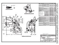
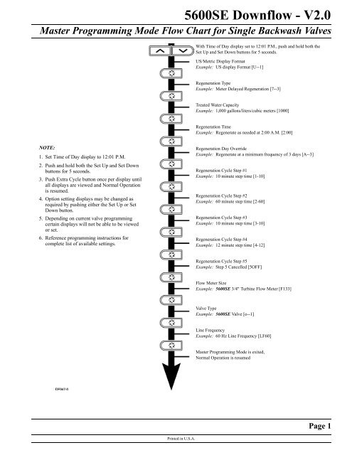
<strong>5600SE</strong> <strong>Downflow</strong> - <strong>V2.0</strong>Master Programming Mode Flow Chart for Single Backwash ValvesWith Time of Day display set to 12:01 P.M., push and hold both theSet Up and Set Down buttons for 5 seconds.US/Metric Display FormatExample: US display Format [U--1]Regeneration TypeExample: Meter Delayed Regeneration [7--3]Treated Water CapacityExample: 1,000 gallons/liters/cubic meters [1000]Regeneration TimeExample: Regenerate as needed at 2:00 A.M. [2:00]NOTE:1. Set Time of Day display to 12:01 P.M.2. Push and hold both the Set Up and Set Downbuttons for 5 seconds.3. Push Extra Cycle button once per display untilall displays are viewed and Normal Operationis resumed.4. Option setting displays may be changed asrequired by pushing either the Set Up or SetDown button.5. Depending on current valve programmingcertain displays will not be able to be viewedor set.6. Reference programming instructions forcomplete list of available settings.Regeneration Day OverrideExample: Regenerate at a minimum frequency of 3 days [A--3]Regeneration Cycle Step #1Example: 10 minute step time [1-10]Regeneration Cycle Step #2Example: 60 minute step time [2-60]Regeneration Cycle Step #3Example: 10 minute step time [3-10]Regeneration Cycle Step #4Example: 12 minute step time [4-12]Regeneration Cycle Step #5Example: Step 5 Cancelled [5OFF]Flow Meter SizeExample: <strong>5600SE</strong> 3/4" Turbine Flow Meter [F133]Valve TypeExample: <strong>5600SE</strong> Valve [o--1]Line FrequencyExample: 60 Hz Line Frequency [LF60]Master Programming Mode is exited,Normal Operation is resumedPage 1Printed in U.S.A.
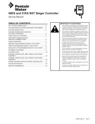
<strong>5600SE</strong> <strong>Downflow</strong> - <strong>V2.0</strong>Master Programming Mode Flow Chart for Double Backwash ValvesWith Time of Day display set to 12:01 P.M., push and hold both theSet Up and Set Down buttons for 5 seconds.US/Metric Display FormatExample: US display Format [U--1]Regeneration TypeExample: Meter Delayed Regeneration [7--3]Treated Water CapacityExample: 1,000 gallons/liters/cubic meters [1000]Regeneration TimeExample: Regenerate as needed at 2:00 A.M. [2:00]Regeneration Day OverrideExample: Regenerate at a minimum frequency of 3 days [A--3]NOTE:1. Set Time of Day display to 12:01 P.M.2. Push and hold both the Set Up and Set Downbuttons for 5 seconds.3. Push Extra Cycle button once per display untilall displays are viewed and Normal Operationis resumed.4. Option setting displays may be changed asrequired by pushing either the Set Up or SetDown button.5. Depending on current valve programmingcertain displays will not be able to be viewedor set.6. Reference programming instructions forcomplete list of available settings.Regeneration Cycle Step #1Example: 10 minute step time [1-10]Regeneration Cycle Step #2Example: 60 minute step time [2-60]Regeneration Cycle Step #3Example: 10 minute step time [3-10]Regeneration Cycle Step #4Example: 10 minute step time [4-10]Regeneration Cycle Step #5Example: 12 minute step time [5-12]Regeneration Cycle Step #6Example: Step 6 Cancelled [6OFF]Flow Meter SizeExample: <strong>5600SE</strong> 3/4" Turbine Flow Meter [F133]Valve TypeExample: <strong>5600SE</strong> Valve [o--1]Line FrequencyExample: 60 Hz Line Frequency [LF60]Master Programming Mode is exited,Normal Operation is resumedPage 2Printed in U.S.A.
Master Programming Mode<strong>5600SE</strong> <strong>Downflow</strong> - <strong>V2.0</strong>Set Up buttonExtra Cycle buttonSet Down buttonWhen the Master Programming Mode is entered, all available option setting displays may be viewed and set as needed. Dependingon current option settings, some displays cannot be viewed or set.Entering Master Programming ModeSet the Time Of Day display to 12:01 P.M. Push and hold the Set Up and Set Down buttons together until the Program Dotturns on (about 5 seconds). Depending on current option settings, some displays cannot be viewed or set.Exiting Master Programming ModePush the Extra Cycle button once per display until all are viewed. The Program Mode is exited and normal operation resumes.Resetting Permanent Programming MemoryPush and hold the Set Up and Set Down buttons for 25 seconds or until the Time Of Day display resets to 12:00 P.M. Alloption settings reset to default values. Control programming must be reset as necessary.1. US/Metric Display Format (U)Push the Extra Cycle button. This display is used to set the desired display format. This option setting is identified by the "U"in the first digit. The possible settings are:US Format uses gallons for volume with a 12-hour timekeeping format. Regeneration timing in minutes.Example: [U - - I]Metric Format uses liters for volume and a 24-hour timekeeping format. Regeneration timing in tenths of minutes. Use theSet Up and Set Down buttons to adjust this value.Example: [U - - 2]Cubic Meter Format uses cubic meters for volume and a 24-hour timekeeping format. Regeneration timing in tenths ofminutes. Use the Set Up and Set Down buttons to adjust this value.Example: [U - - 4]Printed in U.S.A.Page 3
<strong>5600SE</strong> <strong>Downflow</strong> - <strong>V2.0</strong>Master Programming Mode (Cont’d.)2. Regeneration Type (7)Push the Extra Cycle button. Use this display to set the Regeneration Type. This option setting is identified by the number "7"in the first digit. There are three possible settings:Timeclock DelayedThe control determines the day that a regeneration is required by the Regeneration Day Override setting (A). Once this dayis reached, a regeneration cycle starts at the set Regeneration Time.Example: [7 - - I]Meter ImmediateThe control determines that regeneration is required when the available volume of treated water drops to zero. Regenerationbegins immediately.Example:[7 - - 2] (This setting is typically used by the 9000SE)Meter DelayedThe control determines that a regeneration is required when the available volume of treated water drops to zero. Regenerationbegins immediately at the set Regeneration Time. Use the Set Up and Set Down buttons to adjust this value.Example: [7 - - 3]3. Treated Water Capacity (No Display Code)Push the Extra Cycle button. Use this display to set the amount of water (gallons/liters/cubic meters) that can be treated by theunit before a regeneration cycle is required. With Meter Delayed Regeneration Type set, it is necessary for the programmer todetermine a reserve capacity and subtract that value from the calculated full capacity of the unit. This display cannot be viewedwith Timeclock Regeneration Type set. Use the Set Up and Set Down buttons to adjust this value.Example: Regenerate every 700 gallons/liters/cubic meters — [7 0 0]4. Regeneration Time (Clock Display Without a Flashing Colon)Push the Extra Cycle button. The next display that appears is the option setting for Regeneration Time. It is identified by aclock display without a flashing colon. Set the desired time of day that a regeneration may occur. This display cannot beviewed with Meter Immediate Regeneration Type set. Use the Set Up and Set Down buttons to adjust this value.Example:2 o'clock A.M. Regeneration Time — [2: 0 0] (A.M. Indicator Dot On)5. Regeneration Day Override (A)Push the Extra Cycle button. Use this display to set the maximum amount of time (in days) the unit can be in service withouta regeneration. This option setting is identified by the letter "A" in the first digit.– With Timeclock or Meter Delayed Regeneration Types selected, regeneration begins at the set Regeneration Time.– With Meter Immediate Regeneration Type selected, regeneration begins at the same time of day that the last regenerationcycle was initiated. An OFF setting cancels this feature with all regeneration types except Timeclock Regeneration were itmust be used. Use the Set Up and Set Down buttons to adjust this value.Example: Override every 7 days — [A - - 7]Cancel setting — [A O F F] (Meter Immediate or Delayed Regeneration Types Only)Page 4Printed in U.S.A.
<strong>5600SE</strong> <strong>Downflow</strong> - <strong>V2.0</strong>Master Programming Mode (Cont’d.)6. Regeneration Cycle Step Programming (1) (2) (3) (4) (5) (6)Push the Extra Cycle button. The next 2–6 displays that appear are part of a series of option settings used to program theRegeneration Cycle. Each display is used to set in minutes (or tenths of minutes - Metric). A step # turns on for theregeneration cycle step being programmed.– Skip regeneration steps by setting the display to 0– End a regeneration cycle by setting the step # after the last active step to OFF, as shown below:Example:Regeneration Cycle Step #1, 8 minutes — [I - - 8] (US Format)Regeneration Cycle Step #3, skipped — [3 - - 0] (US Format)Regeneration Cycle Step #4, 8.5 minutes — [4 - 8.5] (Both Metric Formats)Regeneration Cycle Step #4, cancelled — [4 O F F] (All Formats)Push the Extra Cycle button once per display to advance through Regeneration Cycle Step Programming.Proper softener operation requires the calculation of a brine tank refill time:(Pounds of Salt Used per Regeneration Cycle ÷ 3) ÷ BLFC Size = Refill Time in MinutesExample: (10 lbs salt ÷ 3) ÷ 0.25 gpm = 13.3 minute refill(Consult valve service manual for actual step location)Use the Set Up and Set Down buttons to adjust this value.7. Flow Meter Size (F)Push the Extra Cycle button. The the next display sets the flowmeter size. Use this display to set the proper amount of pulsesgenerated by the flow meter for each gallon or liter of water flow. This setting cannot be viewed with Timeclock RegenerationType selected.Example: [F I 2 6] 3/4” Turbine Flow Meter used with the 2510SE (US Format)Example: [F 3 3.2] 3/4” Turbine Flow Meter used with the 2510SE (Metric Format)Example: [F 1 3 2] 3/4” Turbine Flow Meter used with the TwinFlo100E (US Format)Example: [F 3 4.9] 3/4” Turbine Flow Meter used with the TwinFlo100E (Metric Format)Example: [F 1 3 3] 3/4” Turbine Flow Meter used with the <strong>5600SE</strong> or 9000SE (US Format)Example: [F 3 5.1] 3/4” Turbine Flow Meter used with the <strong>5600SE</strong> or 9000SE (Metric Format)Example: [F - 2 0] 3/4” Paddle Wheel Flow Meter (US Format)Example: [F - 5.3] 3/4” Paddle Wheel Flow Meter (Metric Format)Example: [F - - 8] 1.0” Paddle Wheel Flow Meter (US Format)Example: [F - 2.1] 1.0” Paddle Wheel Flow Meter (Metric Format)Use the Set Up and Set Down buttons to adjust this value.8. Valve Type (o)Push the Extra Cycle button. Use this display to set the type of valve used with the control. This option setting is identified bythe letter "o" in the first digit. When #2 is selected, the current Tank # in Service must be entered in the next display.Example: [o - - I] 2510SE, 2750SE or <strong>5600SE</strong> Valve Operation.Example: [o - - 2] 9000SE or TwinFlo100E Valve Operation.Example: [o - U I] Unit #1 Tank in Service. (Viewed with #2 set only)Use the Set Up and Set Down buttons to adjust this value.Printed in U.S.A.Page 5
<strong>5600SE</strong> <strong>Downflow</strong> - <strong>V2.0</strong>Master Programming Mode (Cont’d.)9. Line Frequency (LF)Push the Extra Cycle button. Use this display to set the frequency of the power applied to the control. When properly set, alltimekeeping functions remain accurate. This option setting is identified by the letters "LF" in the first two digits. There are twopossible selections.Example:[L F 5 0] 50 Hz Line Frequency Operation.Example:[L F 6 0] 60 Hz Line Frequency Operation.Use the Set Up and Set Down buttons to adjust this value.Push the Extra Cycle button once more to exit this programming mode.Page 6 P/N 41674 Rev. APrinted in U.S.A.