
You also want an ePaper? Increase the reach of your titles
YUMPU automatically turns print PDFs into web optimized ePapers that Google loves.
<strong>ST7565</strong>PADNo.PIN Name X.5 Y303 COM[59] 4777.5 715304 COM[60] 4777.5 780305 COM[61] 4777.5 845306 COM[62] 4777.5 910307 COM[63] 4777.5 975308 COMS 4777.5 1040309 (NC) 4777.5 1119Ver 0.9 6/6 2001/01/11
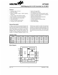
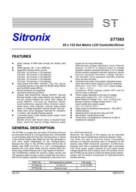
<strong>ST7565</strong>BLOCK DIAGRAMCOMSCOM63COM0SEG131SEG0VDDV1V2V3V4V5132 SEGMENTDRIVERS64 COMMONDRIVERSCOMSCOM output control circuitHPMV5VRVRSIRSVOUTCAP1+CAP1-CAP2+CAP2-CAP3+VSS2VoltagefollowercircuitVoltageRegulatorcircuitVoltageboostercircuitPower SupplyCircuitPage address circuitI/O bufferDisplay data latch circuitDISPLAY DATA RAM65 X 132 = 8580 BitsColumn address circuitLine address circuitDisplay timing generator circuitOscillatorcircuitFRSM/SCLDOFFRCLSVSSStatusCommand decoderBus holderMPU INTERFACE ( Parallel and Serial )D7(SI)D6(SCL)D5D4D3D2D1D0P/SC86/RESCS2CS1A0RW(WR)E(RD)SEL3SEL2SEL1Ver 0.9 7/7 2001/01/11
<strong>ST7565</strong>PIN DESCRIPTIONSPower Supply PinsPin Name I/O Function No. of PinsVDDVSSVSS2VRSPowerSupplyPowerSupplyPowerSupplyPowerSupplyShared with the MPU power supply terminal Vcc. 13This is a 0V terminal connected to the system GND. 9This is the reference power supply for the step-up voltage circuit for theliquid crystal drive.This is the externally-input VREG power supply for the LCD power supplyvoltage regulator.These are only enabled for the models with the VREG external input option.Power This is a multi-level power supply for the liquid crystal drive. The voltageSupply applied is determined by the liquid crystal cell, and is changed throughthe use of a resistive voltage divided or through changing the impedance usingan op. amp. Voltage levels are determined based on VDD, and must maintainthe relative magnitudes shown below.42V1, V2,V3, V4,V5PowerSupplyVDD (= V0) ≧V1 ≧V2 ≧V3 ≧V4 ≧V5When the power supply turns ON, the internal power supply circuits produce theV1 to V4 voltages shown below. The voltagesettings are selected using the LCDbias set <strong>com</strong>mand.101/65 DUTY 1/49 DUTY 1/33 DUTY 1/55 DUTY 1/53 DUTYV1 1/9*V5,1/7*V5 1/8*V5,1/6*V5 1/6*V5,1/5*V5 1/8*V5,1/6*V5 1/8*V5,1/6*V5V2 2/9*V5,2/7*V5 2/8*V5,2/6*V5 2/6*V5,2/5*V5 2/8*V5,2/6*V5 2/8*V5,2/6*V5V3 7/9*V5,5/7*V5 6/8*V5,4/6*V5 4/6*V5,3/5*V5 6/8*V5,4/6*V5 6/8*V5,4/6*V5V4 8/9*V5,6/7*V5 7/8*V5,5/6*V5 5/6*V5,4/5*V5 7/8*V5,5/6*V5 7/8*V5,5/6*V5LCD Power Supply PinsPin Name I/O Function No. of PinsCAP1+CAP1–CAP2+CAP2–CAP3–VOUTVROOOOOOIDC/DC voltage converter. Connect a capacitor between this terminal andthe CAP1- terminal.DC/DC voltage converter. Connect a capacitor between this terminal andthe CAP1+ terminal.DC/DC voltage converter. Connect a capacitor between this terminal andthe CAP2- terminal.DC/DC voltage converter. Connect a capacitor between this terminal andthe CAP2+ terminal.DC/DC voltage converter. Connect a capacitor between this terminal andthe CAP1+ terminal.DC/DC voltage converter. Connect a capacitor between this terminal andVSS.Output voltage regulator terminal. Provides the voltage between VDD andV5 through a resistive voltage divider.IRS = “L” : the V5 voltage regulator internal resistors are not used .IRS = “H” : the V5 voltage regulator internal resistors are used .2222222Ver 0.9 8/8 2001/01/11
<strong>ST7565</strong>System Bus Connection PinsPin Name I/O Function No. of PinsD5 to D0D6 (SCL)D7 (SI)A0I/OIThis is an 8-bit bi-directional data bus that connects to an 8-bit or 16-bitstandard MPU data bus.When the serial interface is selected (P/S = “L”) :D7 : serial data input (SI) ; D6 : the serial clock input (SCL).D0 to D5 are set to high impedance.When the chip select is not active, D0 to D7 are set to high impedance.This is connect to the least significant bit of the normal MPU address bus,and it determines whether the data bits are data or a <strong>com</strong>mand.A0 = “H”: Indicates that D0 to D7 are display data.A0 = “L”: Indicates that D0 to D7 are control data.81RESIWhen RES is set to “L,” the settings are initialized.1The reset operation is performed by the RES signal level.CS1CS2IThis is the chip select signal. When CS1 = “L” and CS2 = “H,” then thechip select be<strong>com</strong>es active, and data/<strong>com</strong>mand I/O is enabled.2RD(E)I• When connected to an 8080 MPU, this is active LOW.(E) This pin is connected to the RD signal of the 8080 MPU, and the<strong>ST7565</strong> series data bus is in an output status when this signal is “L”.• When connected to a 6800 Series MPU, this is active HIGH.This is the 6800 Series MPU enable clock input terminal.1WR(R/W)I• When connected to an 8080 MPU, this is active LOW.(R/W) This terminal connects to the 8080 MPU WR signal. The signals onthe data bus are latched at the rising edge of the WR signal.• When connected to a 6800 Series MPU:This is the read/write control signal input terminal.When R/W = “H”: Read.When R/W = “L”: Write.1C86IThis is the MPU interface switch terminal.C86 = “H”: 6800 Series MPU interface.C86 = “L”: 8080 MPU interface.1This is the parallel data input/serial data input switch terminal.P/S = “H”: Parallel data input.P/S = “L”: Serial data input.The following applies depending on the P/S status:P/S Data/Command Data Read/Write Serial ClockP/SI“H” A0 D0 to D7XRD, WR1“L” A0 SI (D7) Write only SCL (D6)When P/S = “L”, D0 to D5 may be “H”, “L” or Open.RD (E) and WR (R/W) are fixed to either “H” or “L”.With serial data input, It is impossible read data from RAM .Ver 0.9 9/9 2001/01/11
<strong>ST7565</strong>Pin Name I/O Function No. of PinsCLSITerminal to select whether or enable or disable the display clock internaloscillator circuit.CLS = “H” : used Internal oscillator circuit .CLS = “L” : used external clock input .(internal oscillator is disable)When CLS = “L”, input the display clock through the CL terminal.1M/SIThis pin set to VDD1This is the display clock input terminalThe following is true depending on the M/S and CLS status.M/S CLS CLCLI/O“H”“L”“H”“L”“H”“L”OutputInputInputInput1FROThis is the liquid crystal alternating current signal terminal.1DOFFRSIRSOOIThis is the LCD blanking control terminal.This is the output terminal for the static drive.This terminal is only enabled when the static indicator display is ONand is used in conjunction with the FR terminal.This terminal selects the resistors for the V5 voltage level adjustment.IRS = “H”: Use the internal resistorsIRS = “L”: Do not use the internal resistors. The V5 voltage level isregulated by an external resistive voltage divider attached to the VR terminal111HPMIThis is the power control terminal for the power supply circuit for liquid crystaldrive.HPM = “H”: Normal modeHPM = “L”: High power mode1These pins are DUTY selection.SEL 3 , 2 , 1 DUTY BIAS0 , 0 , 0 1/65 1/9 or 1/7SEL3SEL2SEL1I0 , 0 , 1 1/49 1/8 or 1/60 , 1 , 0 1/33 1/6 or 1/50 , 1 , 1 1/55 1/8 or 1/631 , 0 , 0 1/53 1/8 or 1/61, X , X ----- -----TEST1 ~ 10IThese are terminals for IC testing .They are set to open .10Ver 0.9 10/10 2001/01/11
<strong>ST7565</strong>LCD Driver PinsPin Name I/O Function No. of PinsThese are the LCD segment drive outputs. Through a <strong>com</strong>bination of thecontents of the display RAM and with the FR signal, a single level is selectedfrom VDD, V2, V3, and V5.SEG0toSEG131ORAM DATAFRNormal DisplayOutput VoltageReverse DisplayH H VDD V2H L V5 V3132L H V2 VDDL L V3 V5Power saveVDDThese are the LCD <strong>com</strong>mon drive outputs.Part No. COM TOTAL<strong>ST7565</strong> COM0 ~ COM63 64ST7566 COM0 ~ COM47 48ST7567 COM0 ~ COM31 32ST7568 COM0 ~ COM53 54COM0toCOMnOST7569 COM0 ~ COM51 52Through a <strong>com</strong>bination of the contents of the scan data and with the FRsignal, a single level is selected from VDD, V1, V4, and V5.Scan Data FR Output VoltageH H V5H L VDDL H V1L L V4Power saveVDDCOMSOThese are the COM output terminals for the indicator. Both terminals outputthe same signal.Leave these open if they are not used.2Ver 0.9 11/11 2001/01/11
<strong>ST7565</strong>DESCRIPTION OF FUNCTIONSThe MPU InterfaceSelecting the Interface TypeWith the <strong>ST7565</strong> chips, data transfers are done through an8-bit parallel data bus (D7 to D0) or through a serial datainput (SI). Through selecting the P/ S terminal polarity to the“H” or “L” it is possible to select either paralleldata input or serial data input as shown in Table 1.Table 1P/SCS1CS2A0RDWRC86 D7 D6 D5~D0H: Parallel InputCS1CS2 A0RD WRC86 D7 D6 D5~D0L: Serial InputCS1CS2 A0 — — — SI SCL (HZ)“—” indicates fixed to either “H” or to “L”The Parallel InterfaceWhen the parallel interface has been selected (P/S =“H”),then it is possible to connect directly to either an8080-system MPU or a 6800 Series MPU (shown in Table 2)by selecting the C86 terminal to either “H” or to “L”.Table 2C86(P/S=H)CS1CS2A0RDWRD7~D0H: 6800 SeriesCS1CS2 A0 ER/WD7~D0L: 8080 SeriesCS1CS2A0RDWRD7~D0Moreover, data bus signals are recognized by a <strong>com</strong>binationof A0, RD (E), WR (R/W) signals, as shown in Table 3.Table 3Shared 6800 Series 8080 SeriesFunctionA0R/W RD WR1 1 0 1 Reads the display data1 0 1 0 Writes the display data0 1 0 1 Status read0 0 1 0 Write control data (<strong>com</strong>mand)Ver 0.9 12/12 2001/01/11
<strong>ST7565</strong>The Serial InterfaceWhen the serial interface has been selected (P/S = “L”) thenwhen the chip is in active state (CS1 = “L” and CS2 = “H”) theserial data input (SI) and the serial clock input (SCL) can bereceived. The serial data is read from the serial data inputpin in the rising edge of the serial clocks D7, D6 through D0,in this order. This data is converted to 8 bits parallel data inthe rising edge of the eighth serial clock for the processing.The A0 input is used to determine whether or the serial datainput is display data or <strong>com</strong>mand data; when A0 = “H”, thedata is display data, and when A0 = “L” then the data is<strong>com</strong>mand data. The A0 input is read and used for detectionevery 8th rising edge of the serial clock after the chipbe<strong>com</strong>es active. Figure 1 is a serial interface signal chart.Figure 1* When the chip is not active, the shift registers and the counter are reset to their initial states.* Reading is not possible while in serial interface mode.* Caution is required on the SCL signal when it <strong>com</strong>es to line-end reflections and external noise. We re<strong>com</strong>mend that operationbe rechecked on the actual equipment.The Chip SelectThe <strong>ST7565</strong> have two chip select terminals: CS1 and CS2.The MPU interface or the serial interface isenabled only when CS1 = “L” and CS2 = “H”.When the chip select is inactive, D0 to D7 enter a highimpedance state, and the A0, RD, and WR inputs areinactive. When the serial interface is selected, the shiftregister and the counter are reset.The Accessing the Display Data RAM and the Internal RegistersData transfer at a higher speed is ensured since the MPU isrequired to satisfy the cycle time (tCYC) requirement alone inaccessing the <strong>ST7565</strong>. Wait time may not be considered.And, in the <strong>ST7565</strong>, each time data is sent from the MPU, atype of pipeline process between LSIs is performed throughthe bus holder attached to the internal data bus. Internaldata bus.For example, when the MPU writes data to the display dataRAM, once the data is stored in the bus holder, then it iswritten to the display data RAM before the next data writecycle. Moreover, when the MPU reads the display data RAM,the first data read cycle (dummy) stores the read data in thebus holder, and then the data is read from the bus holder tothe system bus at the next data read cycle.There is a certain restriction in the read sequence of thedisplay data RAM. Please be advised that data of thespecified address is not generated by the read instructionissued immediately after the address setup. This data isgenerated in data read of the second time. Thus, a dummyread is required whenever the address setupor write cycle operation is conducted.This relationship is shown in Figure 2.Ver 0.9 13/13 2001/01/11
<strong>ST7565</strong>The Busy FlagWhen the busy flag is “1” it indicates that the <strong>ST7565</strong> isrunning internal processes, and at this time no <strong>com</strong>mandaside from a status read will be received. The busy flag isoutputted to D7 pin with the read instruction. If the cycle time(tCYC) is maintained, it is not necessary to check for this flagbefore each <strong>com</strong>mand. This makes vastimprovements in MPU processing capabilities possible.Figure 2Ver 0.9 14/14 2001/01/11
<strong>ST7565</strong>Display Data RAMDisplay Data RAMThe display data RAM stores the dot data for the LCD. It hasa 65 (8 page x 8 bit +1) x 132 bit structure.as is shown in Figure 3, the D7 to D0 display data from theMPU corresponds to the LCD display <strong>com</strong>mon direction,there are few constraints at the time of display data transferwhen multiple <strong>ST7565</strong> are used, thus and display structurescan be created easily and with a high degree of freedom.Moreover, reading from and writing to the display RAM fromthe MPU side is performed through the I/O buffer, which isan independent operation from signal reading for the liquidcrystal driver. Consequently, even if the display data RAM isaccessed asynchronously during liquid crystal display, it willnot cause adverse effects on the display (such as flickering).Figure 3The Page Address CircuitPage address of the display data RAM is specified throughthe Page Address Set Command. The page address mustbe specified again when changing pages to perform access.Page address 8 (D3, D2, D1, D0 = 1, 0, 0, 0) is a specialRAM for icons, and only display data D0 is used.(see Figure 4)The Column AddressesThe display data RAM column address is specified by theColumn Address Set <strong>com</strong>mand. The specified columnaddress is incremented (+1) with each display dataread/write <strong>com</strong>mand. This allows the MPU display data to beaccessed continuously. Moreover, the incrementation ofcolumn addresses stops with 83H. Because the columnaddress is independent of the page address, when moving,for example, from page 0 column 83H to page 1 column 00H,it is necessary to respecify both the page address and thecolumn address.Furthermore, as is shown in Table 4, the ADC <strong>com</strong>mand(segment driver direction select <strong>com</strong>mand) can be used toreverse the relationship between the display data RAMcolumn address and the segment output. Because of this,the constraints on the IC layout when the LCD module isassembled can be minimized. As is shown in Figure 4,The Line Address CircuitThe line address circuit, as shown in Table 4, specifies theline address relating to the COM output when the contents ofthe display data RAM are displayed. Using the display startline address set <strong>com</strong>mand, what is normally the top line ofthe display can be specified (this is the COM0 output whenthe <strong>com</strong>mon output mode is normal, and the COM63 outputTable 4SEG OutputADC SEG0 SEG 131(D0) “0” 0 (H) → Column Address → 83 (H)(D0) “1” 83 (H) ← Column Address ← 0 (H)for <strong>ST7565</strong> , the detail is shown page.11 The display area isa 65 line area for the <strong>ST7565</strong>.If the line addresses are changed dynamically using thedisplay start line address set <strong>com</strong>mand, screen scrolling,page swapping, etc. can be performed.Ver 0.9 15/15 2001/01/11
<strong>ST7565</strong>Page AddressD3 D2 D1 D0DataLineAddressWhen the <strong>com</strong>monoutput is normalVer 0.9 16/16 2001/01/11COMOutputD0 00H COM0D1 01H COM1D2 02H COM20 0 0 0D3 03H COM3Page 0D4 04H COM4D5 05H COM5D6 06H COM6D707HCOM7D0 08H COM8D1 09H COM9D2 0AH COM100 0 0 1D3 0BH COM11Page 1D4 0CH COM12D5 0DH COM13D6 0EH COM14D70FHCOM15D0 10H COM16D1 11H COM17D2 12H COM180 0 1 0D3 13H COM19Page 2D4 14H COM20D5 15H COM21D6 16H COM22D717HCOM23D0 18H COM24D1 19H COM25D2 1AH COM260 0 1 1D3 1BH COM27Page 3D4 1CH COM28D5 1DH COM29D6 1EH COM30D71FHCOM31D0 20H COM32D1 21H COM33D2 22H COM340 1 0 0D3 23H COM35Page 4D4 24H COM36D5 25H COM37D6 26H COM38D727HCOM39D0 28H COM40D1 29H COM41D2 2AH COM420 1 0 1D3 2BH COM43Page 5D4 2CH COM44D5 2DH COM45D6 2EH COM46D72FHCOM47D0 30H COM48D1 31H COM49D2 32H COM500 1 1 0D3 33H COM51Page 6D4 34H COM52D5 35H COM53D6 36H COM54D737HCOM55D0 38H COM56D1 39H COM57D2 3AH COM580 1 1 1D3 3BH COM59Page 7D4 3CH COM60D5 3DH COM61D6 3EH COM62D73FHCOM631 0 0 0 D0 Page 8 COMS000102030405060708838281807F7E7D7C7BS0S1S2S3S4S5S6S7S8Figure 47B7C7D7E7F80818283080706050403020100S123S124S125S126S127S128S129S130S13101D0ADCD0LCDOutColumnaddressRegardless of the displaystart line address,1/65duty => 65th line,1/49duty =>49th line.1/33duty =>33th line,1/55duty =>55th line,1/53duty =>53th line.
<strong>ST7565</strong>The Display Data Latch CircuitThe display data latch circuit is a latch that temporarilystores the display data that is output to the liquid crystaldriver circuit from the display data RAM.Because the display normal/reverse status, display ON/OFFstatus, and display all points ON/OFF <strong>com</strong>mands controlonly the data within the latch, they do not changethe data within the display data RAM itself.The Oscillator CircuitThis is a CR-type oscillator that produces the display clock.The oscillator circuit is only enabled when M/S= “H” andCLS = “H”.When CLS = “L” the oscillation stops, and the externalclock is input through the CL terminal.Display Timing Generator CircuitThe display timing generator circuit generates the timingsignal to the line address circuit and the display data latchcircuit using the display clock. The display data is latchedinto the display data latch circuit synchronized with thedisplay clock, and is output to the data driver output terminal.Reading to the display data liquid crystal driver circuits is<strong>com</strong>pletely independent of accesses to the display dataRAM by the MPU. Consequently, even if the display dataTwo-frame alternating current drive waveformRAM is accessed asynchronously during liquid crystaldisplay, there is absolutely no adverse effect (such asflickering) on the display.Moreover, the display timing generator circuit generates the<strong>com</strong>mon timing and the liquid crystal alternating currentsignal (FR) from the display clock. It generates a drive waveform using a 2 frame alternating current drive method, as isshown in Figure 5, for the liquid crystal drive circuit.Figure 5Ver 0.9 17/17 2001/01/11
<strong>ST7565</strong>The Common Output Status Select CircuitIn the <strong>ST7565</strong> chips, the COM output scan direction can beselected by the <strong>com</strong>mon output status select <strong>com</strong>mand.(See Table 6.) Consequently, the constraints in IC layout atthe time of LCD module assembly can be minimized.StatusNormalReverseTable 6COM Scan Direction1/65 DUTY 1/49 DUTY 1/33 DUTY 1/55 DUTY 1/53 DUTYCOM0 → COM63COM63 → COM0COM0 → COM47COM47 → COM0COM0 → COM31COM31 → COM0COM0 → COM53COM53 → COM0COM0 → COM51COM51 → COM0Duty1/651/491/331/551/53ComCommon output pinsdir <strong>com</strong>[0:15] <strong>com</strong>[16:23] <strong>com</strong>[24:26] <strong>com</strong>[27:36] <strong>com</strong>[37:39] <strong>com</strong>[40:47] <strong>com</strong>[48:63] <strong>com</strong>s0 <strong>com</strong>[0:63] <strong>com</strong>s1 <strong>com</strong>[63:0] <strong>com</strong>s0 <strong>com</strong>[0:23] <strong>com</strong>[24:47] <strong>com</strong>s1 <strong>com</strong>[47:24] <strong>com</strong>[23:0] <strong>com</strong>s0 <strong>com</strong>[0:15] <strong>com</strong>[16:31] <strong>com</strong>s1 <strong>com</strong>[31:16] <strong>com</strong>[15:0] <strong>com</strong>s0 <strong>com</strong>[0:26] <strong>com</strong>[27:53] <strong>com</strong>s1 <strong>com</strong>[53:27] <strong>com</strong>[26:0] <strong>com</strong>s0 <strong>com</strong>[0:25] <strong>com</strong>[26:51] <strong>com</strong>s1 <strong>com</strong>[51:26] <strong>com</strong>[25:0] <strong>com</strong>sThe LCD Driver CircuitsThese are a 197-channel, that generate four voltage levelsfor driving the LCD . The <strong>com</strong>bination of the display data, theCOM scan signal, and the FR signal produces the liquidcrystal drive voltage output.Figure 6 shows examples of the SEG and COM outputwave form.Ver 0.9 18/18 2001/01/11
<strong>ST7565</strong>Figure 6Ver 0.9 19/19 2001/01/11
<strong>ST7565</strong>The Power Supply CircuitsThe power supply circuits are low-power consumption powersupply circuits that generate the voltage levels required forthe LCD drivers. They are Booster circuits, voltage regulatorcircuits, and voltage follower circuits. They are only enabledin master operation. The power supply circuits can turn theBooster circuits, the voltage regulator circuits, and thevoltage follower circuits ON or OFF independently throughthe use of the Power Control Set <strong>com</strong>mand. Consequently,it is possible to make an external power supply and theinternal power supply function somewhat in parallel. Table 7shows the Power Control Set Command 3-bit data controlfunction, and Table 8 shows reference <strong>com</strong>binations.Table 7bitfunctionStatus“1” “0”D2D1D0Booster circuit control bitVoltage regulator circuit control bit (V/R circuit)Voltage follower circuit control bit (V/F circuit)ONONONOFFOFFOFFThe Control Details of Each Bit of the Power Control Set CommandUse Settings D2 D1 D0Table 8VoltageboosterVoltageregulatorVoltagefollowerExternalvoltageinputStep-upvoltageOnly the internal power supply is used 1 1 1 ON ON ON VSS2 UsedOnly the voltage regulator circuit and thevoltage follower circuit are used0 1 1 OFF ON ON VOUT, VSS2 OpenOnly the V/F circuit is used 0 0 1 OFF OFF ON V5, VSS2 OpenOnly the external power supply is used 0 0 0 OFF OFF OFF V1 to V5 OpenReference Combinations* The “step-up system terminals” refer CAP1+, CAP1–, CAP2+, CAP2–, and CAP3–.* While other <strong>com</strong>binations, not shown above, are also possible, these <strong>com</strong>binations are not re<strong>com</strong>mendedbecause they have no practical use.The Step-up Voltage CircuitsUsing the step-up voltage circuits equipped within the<strong>ST7565</strong> chips it is possible to product a Quad step-up, aTriple step-up, and a Double step-up of the VDD – VSS2voltage levels.Quad step-up: Connect capacitor C1 between CAP1+ andCAP1–, between CAP2+ and CAP2–,between CAP1+ and CAP3–, and betweenVSS2 and VOUT, to produce a voltage level inthe negative direction at the VOUT terminalthat is 4 times the voltage level between VDDand VSS2.Triple step-up: Connect capacitor C1 between CAP1+ andCAP1–, between CAP2+ and CAP2– andbetween VSS2 and VOUT, and short betweenCAP3– and VOUT to produce avoltage levelin the negative direction at the VOUT terminalthat is 3 times the voltage differencebetween VDD and VSS2.Double step-up: Connect capacitor C1 between CAP1+ andCAP1–, and between VSS2 and VOUT, leaveCAP2+ open, and short between CAP2–,CAP3– and VOUT to produce a voltage in thenegative direction at the VOUT terminal thatIs twice the voltage between VDD and VSS2.The step-up voltage relationships are shown in Figure 7.Ver 0.9 20/20 2001/01/11
<strong>ST7565</strong>Figure 7* The VSS2 voltage range must be set so that the VOUT terminal voltage does not exceed the absolute maximum rated value.The Voltage Regulator CircuitThe step-up voltage generated at VOUT outputs the LCDdriver voltage V5 through the voltage regulator circuit.Because the <strong>ST7565</strong> chips have an internal high-accuracyfixed voltage power supply with a 64-level electronic volumefunction and internal resistors for the V5 voltage regulator,systems can be constructed without having to includehigh-accuracy voltage regulator circuit <strong>com</strong>ponents.Moreover, in the <strong>ST7565</strong>, Two types of thermal gradientshave been prepared as VREG options: (1) approximately-0.15%/°C (2) external input (supplied to the VRS terminal).(A) When the V5 Voltage Regulator Internal Resistors Are UsedThrough the use of the V5 voltage regulator internal resistorsand the electronic volume function the liquid crystal powersupply voltage V5 can be controlled by <strong>com</strong>mands alone(without adding any external resistors), making it possible toadjust the liquid crystal display brightness. The V5 voltagecan be calculated using equation A-1 over the range where| V5 | < | VOUT |.Ver 0.9 21/21 2001/01/11
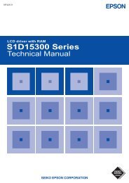
<strong>ST7565</strong>Figure 8VREG is the IC-internal fixed voltage supply, and its voltage at Ta = 25°C is as shown in Table 9.Table 9Part no. Equipment Type Thermal Gradient VREG<strong>ST7565</strong>-0A (1) Internal Power Supply –0.15 %/°C –2.1V<strong>ST7565</strong>-0B (2) External Input — VRSα is set to 1 level of 64 possible levels by the electronic volume function depending on the data set in the 6-bit electronicvolume register. Table 10 shows the value for α depending on the electronic volume register settings.Rb/Ra is the V5 voltage regulator internal resistor ratio, and can be set to 8 different levels through the V5 voltage regulatorinternal resistor ratio set <strong>com</strong>mand. The (1 + Rb/Ra) ratio assumes the values shown in Table 11 depending on the 3-bit datasettings in the V5 voltage regulator internal resistor ratio register.Table 10D5 D4 D3 D2 D1 D0 α0 0 0 0 0 00 0 0 0 0 10 0 0 0 1 0::1 1 1 1 0 11 1 1 1 1 01 1 1 1 1 1636261::210Ver 09 22/22 2001/01/11
<strong>ST7565</strong>V5 voltage regulator internal resistance ratio register value and (1 + Rb/Ra) ratio (Reference value)Table 11Register <strong>ST7565</strong>-0A <strong>ST7565</strong>-0BD2 D1 D0 (1) –0.15 %/°C (2) VRS External Input0 0 00 0 10 1 00 1 11 0 01 0 11 1 01 1 13.03.54.04.55.05.56.06.41.52.02.53.03.54.04.55.0Figures 9, 10 show V5 voltage measured by values of the internal resistance ratio resistor for V5 voltage adjustment andelectric volume resister for each temperature grade model.Ta = 25 °C and booster off ,regulator,follower on , VOUT=-13V , VSS=-3VV5UNIT:V-14-13-12-11-10-9-8-7-6-5-4-3-2-1000H 18H 30H 3FH111110101100011010001000V5 voltage regulatorinternal resistor ratio setD2,D1,D0Electronic volumeregisteredD5 ~ D0Figure 9 : (1) For <strong>ST7565</strong>-0A the Thermal Gradient = -0.15%/°CThe V5 voltage as a function of the V5 voltage regulator internal resistor ratio register and the electronic volume register.Ver 09 23/23 2001/01/11
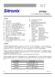
<strong>ST7565</strong>Ta = 25 °C and booster off ,regulator,follower on , VOUT=-13V , VSS=-3V,VRS=-2.6VV5UNIT:V-14-13-12-11-10-9-8-7-6-5-4-3-2-1000H 18H 30H 3FH111110101100011010001000V5 voltage regulatorinternal resistor ratio setD2,D1,D0Electronic volumeregisteredD5 ~ D0Figure 10 : (2) For <strong>ST7565</strong>-0B with External Input VRSThe V5 voltage as a function of the V5 voltage regulator internal resistor ratio register and the electronic volume register.Setup example: When selecting Ta = 25°C and V5 = –7V for an <strong>ST7565</strong>-0A on which Temperature gradient = –0.15%/°C.Using Figure 9 and the equation A-1, the following setup is enabled.At this time, the variable range and the notch width of the V5 voltage is, as shown Table 13, as dependent on the electronicvolume.Table 12RegisterContentsD5 D4 D3 D2 D1 D0For V5 voltage regulator — — — 0 1 0Electronic Volume1 0 0 1 0 1Table 13V5 Min Typ Max UnitsVariable RangeNotch width–8.4 (63 levels) –6.8 (central value) –5.1 (0 level) [V]51 [mV]Ver 09 24/24 2001/01/11
<strong>ST7565</strong>(B) When an External Resistance is Used (The V5 Voltage Regulator Internal Resistors Are Not Used) (1)The liquid crystal power supply voltage V5 can also be setwithout using the V5 voltage regulator internal resistors (IRSterminal = “L”) by adding resistors Ra’ and Rb’ between VDDand VR, and between VR and V5, respectively. When this isdone, the use of the electronic volume function makes itpossible to adjust the brightness of the liquid crystal displayby controlling the liquid crystal power supply voltage V5through <strong>com</strong>mands.In the range where | V5 | < | VOUT |, the V5 voltage can becalculated using equation B-1 based on the externalresistances Ra’ and Rb’.Figure 11Setup example: When selecting Ta = 25°C and V5 = –7 V for<strong>ST7565</strong>-0A the temperature gradient = –0.15%/°C.When the central value of the electron volume register is(D5, D4, D3, D2, D1, D0) = (1, 0, 0, 0, 0, 0), then α = 31 andVREG = –2.1V so, according to equation B-1,Consequently, by equations B-2 and B-3,At this time, the V5 voltage variable range and notchwidth, based on the electron volume function, is asgiven in Table 14.Moreover, when the value of the current running throughRa’ and Rb’ is set to 5 uA,Table 14V5 Min Typ Max UnitsVariable RangeNotch width–8.6 (63 levels) –7.0 (central value) –5.3 (0 level) [V]52 [mV]Ver 09 25/25 2001/01/11
<strong>ST7565</strong>(C) When External Resistors are Used (The V5 Voltage Regulator Internal Resistors Are Not Used) (2)When the external resistor described above are used,adding a variable resistor as well makes it possible toperform fine adjustments on Ra’ and Rb’, to set the liquidcrystal drive voltage V5. In this case, the use of the electronicvolume function makes it possible to control the liquid crystalpower supply voltage V5 by <strong>com</strong>mands to adjust the liquidcrystal display brightness.In the range where | V5 | < | VOUT | the V5 voltage can becalculated by equation C-1 below based on the R1 and R2(variable resistor) and R3 settings, where R2 canbe subjected to fine adjustments (Δ R2).Figure 12Setup example: When selecting Ta = 25°C and V5 = –5 to –9V (using R2) for an <strong>ST7565</strong>-0A the temperature gradient= –0.15%/°C.When the central value for the electronic volume register isset at (D5, D4, D3, D2, D1, D0) = (1, 0, 0, 0, 0, 0), then α =31 and VREG = –2.1 V so, according to equation C-1, whenΔR2 = 0 Ω, in order to make V5 = –9 V,When the current flowing VDD and V5 is set to 5 uA,With this, according to equation C-2, C-3 and C-4,When ΔR2 = R2, in order to make V = –5 V,The V5 voltage variable range and notch width based on theelectron volume function is as shown in Table 15.Table 15V5 Min Typ Max UnitsVariable RangeNotch width–8.7 (63 levels) –7.0 (central value) –5.3 (0 level) [V]53 [mV]Ver 0.9 26/26 2001/01/11
<strong>ST7565</strong>* When the V5 voltage regulator internal resistors or the electronic volume function is used, it is necessary to at least set thevoltage regulator circuit and the voltage follower circuit to an operating mode using the power control set <strong>com</strong>mands.Moreover, it is necessary to provide a voltage from VOUT when the Booster circuit is OFF.* The VR terminal is enabled only when the V5 voltage regulator internal resistors are not used (i.e. the IRS terminal = “L”).When the V5 voltage regulator internal resistors are used (i.e. when the IRS terminal = “H”), then the VR terminalis left open.* Because the input impedance of the VR terminal is high, it is necessary to take into consideration short leads, shieldcables, etc. to handle noise.The LCD Voltage Generator CircuitThe V5 voltage is produced by a resistive voltage dividerwithin the IC, and can be produced at the V1, V2, V3, and V4voltage levels required for liquid crystal driving. Moreover,when the voltage follower changes the impedance, itprovides V1, V2, V3 and V4 to the liquid crystal drive circuit.High Power ModeThe power supply circuit equipped in the <strong>ST7565</strong> chips hasvery low power consumption (normal mode: HPM = “H”).However, for LCDs or panels with large loads, this low-powerpower supply may cause display quality to degrade. Whenthis occurs, setting the HPM terminal to “L” (high powermode) can improve the quality of the display. Were<strong>com</strong>mend that the display be checked on actualequipment to determine whether or not to use this mode.Moreover, if the improvement to the display is inadequateeven after high power mode has been set, then it isnecessary to add a liquid crystal drive power supplyexternally.The Internal Power Supply Shutdown Command SequenceThe sequence shown in Figure 13 is re<strong>com</strong>mended forshutting down the internal power supply, first placing thepower supply in power saver mode and then turningthe power supply OFF.Sequence Details Command address(Command, status) D7 D6 D5 D4 D3 D2 D1 D0Step1 Display OFF 1 0 1 0 1 1 1 0 Power saverStep2 Display all points ON 1 0 1 0 0 1 0 1 <strong>com</strong>mandsEnd Internal power supply OFF (<strong>com</strong>pound)Figure 13The temperature grade of the Internal Power Supply for <strong>ST7565</strong>-0A (-0.15%/°C) :10V9V8V7VTa=-40°C , V5=9.40VTa=25°C , V5=8.46VTa=85°C , V5=7.60VV5 0V-40°C -20°C 0°C 25°C 50°C 85°CTaFigure 14Ver 0.9 27/27 2001/01/11
<strong>ST7565</strong>Reference Circuit ExamplesFigure 15 shows reference circuit examples.1. When used all of the step-up circuit, voltage regulating circuit and V/F circuit(1) When the voltage regulator internal resistor(2) When the voltage regulator internal resistoris used.is not used.(Example where VSS2 = VSS, with 4x step-up)(Example where VSS2 = VSS, with 4x step-up)2. When the voltage regulator circuit and V/F circuit alone are used(1) When the V5 voltage regulator internal resistor (2) When the V5 voltage regulator internal resistoris not used.is used.Ver 0.9 28/28 2001/01/11
<strong>ST7565</strong>3. When the V/F circuit alone is used 4. When the built-in power is not used5. When the built-in power circuit is used to drive a liquidcrystal panel heavily loaded with AC or DC, it isre<strong>com</strong>mended to connect an external resistor to stabilizepotentials of V1, V2, V3 and V4 which are output from thebuilt-in voltage follower.Examples of shared reference settings When V5 can varybetween –8 and 12 VReference set value R4: 100KΩ ~ 1MΩ It is re<strong>com</strong>mendedto set an optimumFigure 15resistance value R4 taking the liquid crystal display and thedrive waveform.* 1. Because the VR terminal input impedance is high, use short leads and shielded lines.* 2. C1 and C2 are determined by the size of the LCD being driven. Select a value that will stabilize the liquid crystal drivevoltage.Example of the Process by which to Determine the Settings:• Turn the voltage regulator circuit and voltage follower circuit ON and supply a voltage to VOUT from the outside.• Determine C2 by displaying an LCD pattern with a heavy load (such as horizontal stripes) and selecting a C2 that stabilizesthe liquid crystal drive voltages (V1 to V5). Note that all C2 capacitors must have the same capacitance value.• Next turn all the power supplies ON and determine C1.Ver 0.9 29/29 2001/01/11
<strong>ST7565</strong>The Reset CircuitWhen the RES input <strong>com</strong>es to the “L” level, these LSIsreturn to the default state. Their default states are as follows:1. Display OFF2. Normal display3. ADC select: Normal (ADC <strong>com</strong>mand D0 = “L”)4. Power control register: (D2, D1, D0) = (0, 0, 0)5. Serial interface internal register data clear6. LCD power supply bias rate:1/65 DUTY = 1/9 bias1/49,1/55,1/53 DUTY = 1/8 bias1/33 DUTY = 1/6 bias7. All-indicator lamps-on OFF (All-indicator lamps ON/OFF<strong>com</strong>mand D0 = “L”)8. Power saving clear9. V5 voltage regulator internal resistors Ra and Rbseparation10. Output conditions of SEG and COM terminals SEG :V2/V3, COM : V1/V411. Read modify write OFF12. Static indicator OFF Static indicator register : (D1, D2) =(0, 0)13. Display start line set to first line14. Column address set to Address 015. Page address set to Page 016. Common output status normal17. V5 voltage regulator internal resistor ratio set mode clear18. Electronic volume register set mode clear Electronicvolume register :(D5, D4, D3, D2, D1, D0) = (1, 0. 0, 0, 0,0)19. Test mode clearOn the other hand, when the reset <strong>com</strong>mand is used, theabove default settings from 11 to 19 are only executed.When the power is turned on, the IC internal state be<strong>com</strong>esunstable, and it is necessary to initialize it using the RESterminal. After the initialization, each input terminal shouldbe controlled normally.Moreover, when the control signal from the MPU is in thehigh impedance, an overcurrent may flow to the IC. Afterapplying a current, it is necessary to take proper measuresto prevent the input terminal from getting into the highimpedance state.If the internal liquid crystal power supply circuit is not usedon <strong>ST7565</strong>,it is necessary that RES is “H” when the externalliquid crystal power supply is turned on. This IC has thefunction to discharge V5 when RES is “L,” and the externalpower supply short-circuits to VDD when RES is “L.”While RES is “L,” the oscillator and the display timinggenerator stop, and the CL, FR, FRS and DOF terminals arefixed to “H.” The terminals D0 to D7 are not affected. TheVDD level is output from the SEG and COM output terminals.This means that an internal resistor is connected betweenVDD and V5.When the internal liquid crystal power supply circuit is notused on other models of <strong>ST7565</strong> series, it is necessary thatRES is “L” when the external liquid crystal power supply isturned on.While RES is “L,” the oscillator works but the display timinggenerator stops, and the CL, FR, FRS and DOF terminalsare fixed to “H.” The terminals D0 to D7 are not affected.Ver 0.9 30/30 2001/01/11
<strong>ST7565</strong>COMMANDSThe <strong>ST7565</strong> identify the data bus signals by a <strong>com</strong>bination of A0, RD (E), WR(R/W) signals. Command interpretation andexecution does not depend on the external clock, but rather is performed through internal timing only, andthus the processing is fast enough that normally a busy check is not required.In the 8080 MPU interface, <strong>com</strong>mands are launched by inputting a low pulse to the RD terminal for reading, and inputting a lowpulse to the WR terminal for writing. In the 6800 Series MPU interface, the interface is placed in a read mode when an “H”signal is input to the R/W terminal and placed in a write mode when a “L” signal is input to the R/W terminal and then the<strong>com</strong>mand is launched by inputting a high pulse to the E terminal. Consequently, the 6800 Series MPU interface is different thanthe 80x86 Series MPU interface in that in the explanation of <strong>com</strong>mands and the display <strong>com</strong>mands the status read and displaydata read RD (E) be<strong>com</strong>es “1(H)”. In the explanations below the <strong>com</strong>mands are explained using the 8080 Series MPUinterface as the example.When the serial interface is selected, the data is input in sequence starting with D7.Display ON/OFFThis <strong>com</strong>mand turns the display ON and OFF.ER/WA0 RD WRD7 D6 D5 D4 D3 D2 D1 D0 Setting0 1 0 1 0 1 0 1 1 1 1 Display ON0 Display OFFWhen the display OFF <strong>com</strong>mand is executed when in the display all points ON mode, power saver mode is entered. See thesection on the power saver for details.Display Start Line SetThis <strong>com</strong>mand is used to specify the display start line address of the display data RAM shown in Figure 4. For further detailssee the explanation of this function in “The Line Address Circuit”.E R/WA0 RD WR0 1 0D7 D6 D5 D4 D3 D2 D1 D0 Line address0 1 0 0 0 0 0 00 0 0 0 0 10 0 0 0 1 0↓1 1 1 1 1 01 1 1 1 1 1012↓6263Page Address SetThis <strong>com</strong>mand specifies the page address corresponding to the low address when the MPU accesses the display data RAM(see Figure 4). Specifying the page address and column address enables to access a desired bit of the display data RAM.Changing the page address does not ac<strong>com</strong>pany a change in the status display.E R/WA0 RD WR0 1 0D7 D6 D5 D4 D3 D2 D1 D0 Page address1 0 1 1 0 0 0 00 0 0 10 0 1 0↓0 1 1 11 0 0 0012↓78Ver 0.9 31/31 2001/01/11
<strong>ST7565</strong>Column Address SetThis <strong>com</strong>mand specifies the column address of the display data RAM shown in Figure 4. The column address is split into twosections (the higher 4 bits and the lower 4 bits) when it is set (fundamentally, set continuously). Each time the display data RAMis accessed, the column address automatically increments (+1), making it possible for the MPU to continuously read from/writeto the display data. The column address increment is topped at 83H. This does not change the page address continuously. Seethe function explanation in “The Column Address Circuit,” for details.High bits →Low bits →E R/WA0 RD WR0 1 0D7 D6 D5 D4 D3 D2 D1 D0 A7 A6 A5 A4 A3 A2 A1 A00 0 0 1 A7 A6 A5 A4 0 0 0 0 0 0 0 00 A3 A2 A1 A0 0 0 0 0 0 0 0 10 0 0 0 0 0 1 0↓1 0 0 0 0 0 1 01 0 0 0 0 0 1 1Columnaddress012↓130131Status ReadE R/WA0 RD WRD7 D6 D5 D4 D3 D2 D1 D00 0 1 BUSY ADC ON/OFF RESET 0 0 0 0BUSYADCON/OFFRESETBUSY = 1: it indicates that either processing is occurring internally or a reset condition is in process.BUSY = 0: A new <strong>com</strong>mand can be accepted . if the cycle time can be satisfied, there is no need to checkfor BUSY conditions.This shows the relationship between the column address and the segment driver.0: Reverse (column address 131-n ↔ SEG n)1: Normal (column address n ↔ SEG n)(The ADC <strong>com</strong>mand switches the polarity.)ON/OFF: indicates the display ON/OFF state.0: Display ON1: Display OFF(This display ON/OFF <strong>com</strong>mand switches the polarity.)This indicates that the chip is in the process of initialization either because of a RES signal or because of areset <strong>com</strong>mand.0: Operating state1: Reset in progressDisplay Data WriteThis <strong>com</strong>mand writes 8-bit data to the specified display data RAM address. Since the column address is automaticallyincremented by “1” after the write, the MPU can write the display data.E R/WA0 RD WRD7 D6 D5 D4 D3 D2 D1 D01 1 0 Write dataVer 0.9 32/32 2001/01/11
<strong>ST7565</strong>Display Data ReadThis <strong>com</strong>mand reads 8-bit data from the specified display data RAM address. Since the column address is automaticallyincremented by “1” after the read, the CPU can continuously read multiple-word data. One dummy read is required immediatelyafter the column address has been set. See the function explanation in “Display Data RAM” for the explanation of accessing theinternal registers. When the serial interface is used, reading of the display data be<strong>com</strong>es unavailable.E R/WA0 RD WRD7 D6 D5 D4 D3 D2 D1 D01 0 1 Read dataADC Select (Segment Driver Direction Select)This <strong>com</strong>mand can reverse the correspondence between the display RAM data column address and the segment driver output.Thus, sequence of the segment driver output pins may be reversed by the <strong>com</strong>mand. See the column address circuit (page1–20) for the detail. Increment of the column address (by “1”) ac<strong>com</strong>panying the reading or writing the display data is doneaccording to the column address indicated in Figure 4.ER/WA0 RD WRD7 D6 D5 D4 D3 D2 D1 D0 Setting0 1 0 1 0 1 0 0 0 0 0 Normal1 ReverseDisplay Normal/ReverseThis <strong>com</strong>mand can reverse the lit and unlit display without overwriting the contents of the display data RAM. When this is donethe display data RAM contents are maintained.ER/WA0 RD WRD7 D6 D5 D4 D3 D2 D1 D0 Setting0 1 0 1 0 1 0 0 1 1 01RAM Data “H”LCD ON voltage (normal)RAM Data “L”LCD ON voltage (reverse)Display All Points ON/OFFThis <strong>com</strong>mand makes it possible to force all display points ON regardless of the content of the display data RAM. The contentsof the display data RAM are maintained when this is done. This <strong>com</strong>mand takes priority over the display normal/reverse<strong>com</strong>mand.ER/WA0 RD WRD7 D6 D5 D4 D3 D2 D1 D0 Setting0 1 0 1 0 1 0 0 1 0 0 Normal display mode1 Display all points ONWhen the display is in an OFF mode, executing the display all points ON <strong>com</strong>mand will place the display in power save mode.For details, see the Power Save section.Ver 0.9 33/33 2001/01/11
<strong>ST7565</strong>LCD Bias SetThis <strong>com</strong>mand selects the voltage bias ratio required for the liquid crystal display.E R/WA0 RD WR0 1 0Select StatusD7 D6 D5 D4 D3 D2 D1 D0 1/65duty 1/49duty 1/33duty 1/55duty 1/53duty1 0 1 0 0 0 1 0 1/9 bias 1/8 bias 1/6 bias 1/8 bias 1/8 bias1 1/7 bias 1/6 bias 1/5 bias 1/6 bias 1/6 biasRead/Modify/WriteThis <strong>com</strong>mand is used paired with the “END” <strong>com</strong>mand. Once this <strong>com</strong>mand has been input, the display data read <strong>com</strong>manddoes not change the column address, but only the display data write <strong>com</strong>mand increments (+1) the column address. Thismode is maintained until the END <strong>com</strong>mand is input. When the END <strong>com</strong>mand is input, the column address returns to theaddress it was at when the read/modify/write <strong>com</strong>mand was entered. This function makes it possible to reduce the load on theMPU when there are repeating data changes in a specified display region, such as when there is a blanking cursor.E R/WA0 RD WRD7 D6 D5 D4 D3 D2 D1 D00 1 0 1 1 1 0 0 0 0 0* Even in read/modify/write mode, other <strong>com</strong>mands aside from display data read/write <strong>com</strong>mands can also be used.However, the column address set <strong>com</strong>mand cannot be used.Page address setColumn address setRead-modify-write cycleDummy readData readData writeNOChangesFinished ?YESENDFigure 24 Command Sequence For read modify writeVer 0.9 34/34 2001/01/11
<strong>ST7565</strong>Column addressN N+1 N+2 N+3 N+m NReturnRead-modify-write mode setEndFigure 25EndThis <strong>com</strong>mand releases the read/modify/write mode, and returns the column address to the address it was at when the modewas entered.E R/WA0 RD WRD7 D6 D5 D4 D3 D2 D1 D00 1 0 1 1 1 0 1 1 1 0ResetThis <strong>com</strong>mand initializes the display start line, the column address, the page address, the <strong>com</strong>mon output mode, the V5 voltageregulator internal resistor ratio, the electronic volume, and the static indicator are reset, and the read/modify/write mode andtest mode are released. There is no impact on the display data RAM. See the function explanation in “Reset” for details.The reset operation is performed after the reset <strong>com</strong>mand is entered.E R/WA0 RD WRD7 D6 D5 D4 D3 D2 D1 D00 1 0 1 1 1 0 0 0 1 0The initialization when the power supply is applied must be done through applying a reset signal to the RES terminal. The reset<strong>com</strong>mand must not be used instead.Common Output Mode SelectThis <strong>com</strong>mand can select the scan direction of the COM output terminal. For details, see the function explanation in“Common Output Mode Select Circuit.”E R/WSelected ModeA0 RD WR D7 D6 D5 D4 D3 D2 D1 D0 1/65duty 1/49duty 1/33duty 1/55duty 1/53duty1 1 0 0 0 * * * Normal COM0→COM63 COM0→COM47 COM0→COM31 COM0→COM53 COM0→COM510 1 01Reverse COM63→COM0 COM47→COM0 COM31→COM0 COM53→COM0 COM51→COM0* Disabled bitVer 0.9 35/35 2001/01/11
<strong>ST7565</strong>Power Controller SetThis <strong>com</strong>mand sets the power supply circuit functions. See the function explanation in “The Power Supply Circuit,” for detailsE R/WA0 RD WR0 1 0D7 D6 D5 D4 D3 D2 D1 D00 0 1 0 1 010101Selected ModeBooster circuit: OFFBooster circuit: ONVoltage regulator circuit: OFFVoltage regulator circuit: ONVoltage follower circuit: OFFVoltage follower circuit: ONV5 Voltage Regulator Internal Resistor Ratio SetThis <strong>com</strong>mand sets the V5 voltage regulator internal resistor ratio. For details, see the function explanation is “The VoltageRegulator circuit " and table 11 .E R/WA0 RD WR0 1 0D7 D6 D5 D4 D3 D2 D1 D00 0 1 0 0 0 0 00 0 10 1 0↓1 1 11 1 1Rb/Ra RatioSmall↓LargeThe Electronic Volume (Double Byte Command)This <strong>com</strong>mand makes it possible to adjust the brightness of the liquid crystal display by controlling the LCD drive voltage V5through the output from the voltage regulator circuits of the internal liquid crystal power supply. This <strong>com</strong>mand is a two byte<strong>com</strong>mand used as a pair with the electronic volume mode set <strong>com</strong>mand and the electronic volume register set<strong>com</strong>mand, and both <strong>com</strong>mands must be issued one after the other.The Electronic Volume Mode SetWhen this <strong>com</strong>mand is input, the electronic volume register set <strong>com</strong>mand be<strong>com</strong>es enabled. Once the electronic volumemode has been set, no other <strong>com</strong>mand except for the electronic volume register <strong>com</strong>mand can be used. Once the electronicvolume register set <strong>com</strong>mand has been used to set data into the register, then the electronic volume mode is released.E R/WA0 RD WRD7 D6 D5 D4 D3 D2 D1 D00 1 0 1 0 0 0 0 0 0 1Ver 0.9 36/36 2001/01/11
<strong>ST7565</strong>Electronic Volume Register SetBy using this <strong>com</strong>mand to set six bits of data to the electronic volume register, the liquid crystal drive voltage V5 assumes oneof the 64 voltage levels.When this <strong>com</strong>mand is input, the electronic volume mode is released after the electronic volume register has been set.E R/WA0 RD WRD7 D6 D5 D4 D3 D2 D1 D0| V5 |* * 0 0 0 0 0 1 Small* * 0 0 0 0 1 0* * 0 0 0 0 1 10 1 0↓↓* * 1 1 1 1 1 0* * 1 1 1 1 1 1 Large* Inactive bitWhen the electronic volume function is not used, set this to (1, 0, 0, 0, 0, 0)The Electronic Volume Register Set Sequenceelectronic volume mode setelectronic volume register setNOSet <strong>com</strong>plete ?Electronic volume mode clearYESFigure 26Static Indicator (Double Byte Command)This <strong>com</strong>mand controls the static drive system indicator display. The static indicator display is controlled by this <strong>com</strong>mand only,and is independent of other display control <strong>com</strong>mands.This is used when one of the static indicator liquid crystal drive electrodes is connected to the FR terminal, and the other isconnected to the FRS terminal. A different pattern is re<strong>com</strong>mended for the static indicator electrodes than for the dynamic driveelectrodes. If the pattern is too close, it can result in deterioration of the liquid crystal and of the electrodes.The static indicator ON <strong>com</strong>mand is a double byte <strong>com</strong>mand paired with the static indicator register set <strong>com</strong>mand, and thusone must execute one after the other. (The static indicator OFF <strong>com</strong>mand is a single byte <strong>com</strong>mand.)Static Indicator ON/OFFWhen the static indicator ON <strong>com</strong>mand is entered, the static indicator register set <strong>com</strong>mand is enabled. Once the staticindicator ON <strong>com</strong>mand has been entered, no other <strong>com</strong>mand aside from the static indicator register set <strong>com</strong>mand can be used.This mode is cleared when data is set in the register by the static indicator register set <strong>com</strong>mand.E R/WA0 RD WR0 1 0D7 D6 D5 D4 D3 D2 D1 D01 0 1 0 1 1 0 01Static IndicatorOFFONVer 0.9 37/37 2001/01/11
<strong>ST7565</strong>Static Indicator Register SetThis <strong>com</strong>mand sets two bits of data into the static indicator register, and is used to set the static indicator into a blinking mode.ER/WA0 RD WR0 1 0* Disabled bitD7 D6 D5 D4 D3 D2 D1 D0* * * * * * 0 00 11 01 1Static Indicator Register Set SequenceIndicator Display StateOFFON (blinking at approximately one second intervals)ON (blinking at approximately 0.5 second intervals)ON (constantly on)Static indicator mode setStatic indicator register setNOSet <strong>com</strong>plete ?Static indicator mode clearYESFigure 27Power Save (Compound Command)When the display all points ON is performed while the display is in the OFF mode, the power saver mode is entered, thusgreatly reducing power consumption.The power saver mode has two different modes: the sleep mode and the standby mode. When the static indicator is OFF, it isthe sleep mode that is entered. When the static indicator is ON, it is the standby mode that is entered.In the sleep mode and in the standby mode, the display data is saved as is the operating mode that was in effect before thepower saver mode was initiated, and the MPU is still able to access the display data RAM.Refer to figure 28 for power save off sequence.Static indicator OFFStatic indicator ONDisplay OFFDisplay OFFDisplay all point ONDisplay all point ONSleep modeStandby modePower save OFFDisplay all point OFFStatic indicator ON (2 bytes)Power save OFF( Display all point OFF )Sleep mode cancelStandby mode cancelFigure 28Ver 0.9 38/38 2001/01/11
<strong>ST7565</strong>Sleep ModeThis stops all operations in the LCD display system, and as long as there are no accesses from the MPU, the consumptioncurrent is reduced to a value near the static current. The internal modes during sleep mode are as follows:1. The oscillator circuit and the LCD power supply circuit are halted.2. All liquid crystal drive circuits are halted, and the segment in <strong>com</strong>mon drive outputs output a VDD level.Standby ModeThe duty LCD display system operations are halted and only the static drive system for the indicator continues to operate,providing the minimum required consumption current for the static drive. The internal modes are in the following states duringstandby mode.1 The LCD power supply circuits are halted. The oscillator circuit continues to operate.2 The duty drive system liquid crystal drive circuits are halted and the segment and <strong>com</strong>mon driver outputs output a VDD level.The static drive system does not operate.When a reset <strong>com</strong>mand is performed while in standby mode, the system enters sleep mode.* When an external power supply is used, it is re<strong>com</strong>mended that the functions of the external power supply circuit be stoppedwhen the power saver mode is started. For example, when the various levels of liquid crystal drive voltage are provided byexternal resistive voltage dividers, it is re<strong>com</strong>mended that a circuit be added in order to cut the electrical current flowingthrough the resistive voltage divider circuit when the power saver mode is in effect. The <strong>ST7565</strong> series chips have a liquidcrystal display blanking control terminal DOF. This terminal enters an “L” state when the power saver mode is launched.Using the output of DOF, it is possible to stop the function of an external power supply circuit.* When the master is turned on, the oscillator circuit is operable immediately after the powering on.NOPNon-OPeration CommandE R/WA0 RD WRD7 D6 D5 D4 D3 D2 D1 D00 1 0 1 1 1 0 0 0 1 1TestThis is a <strong>com</strong>mand for IC chip testing. Please do not use it. If the test <strong>com</strong>mand is used by accident, it can be cleared byapplying a “L” signal to the RES input by the reset <strong>com</strong>mand or by using an NOP.ER/WA0 RD WRD7 D6 D5 D4 D3 D2 D1 D00 1 0 1 1 1 1 * * * ** Inactive bitNote: The <strong>ST7565</strong> maintain their operating modes until something happens to change them. Consequently, excessiveexternal noise, etc., can change the internal modes of the <strong>ST7565</strong> . Thus in the packaging and system design it isnecessary to suppress the noise or take measure to prevent the noise from influencing the chip. Moreover, it isre<strong>com</strong>mended that the operating modes be refreshed periodically to prevent the effects of unanticipatednoise.Ver 0.9 39/39 2001/01/11
<strong>ST7565</strong>CommandTable 16: Table of <strong>ST7565</strong> CommandsCommand CodeFunctionA0 RD WR D7 D6 D5 D4 D3 D2 D1 D01 0 1 0 1 1 1 0 LCD display ON/OFF(1) Display ON/OFF 0 1 01 0: OFF, 1: ONSets the display RAM display start(2) Display start line set 0 1 0 0 1 Display start addressline address(3) Page address set 0 1 0 1 0 1 1 Page addressSets the display RAM pageaddress(4) Column address set 0 1 0 0 0 0 1 Most significant Sets the most significant 4 bits ofupper bitcolumn address the display RAM column address.Column address set 0 1 0 0 0 0 0 Least significant Sets the least significant 4 bits oflower bitcolumn address the display RAM column address.(5) Status read 0 0 1 Status 0 0 0 0 Reads the status data(6) Display data write 1 1 0 Write data Writes to the display RAM(7) Display data read 1 0 1 Read data Reads from the display RAM(8) ADC select 0 1 0(9) Display normal/reverse(10) Display all pointsON/OFF0 1 00 1 0(11) LCD bias set 0 1 01 0 1 0 0 0 0 011 0 1 0 0 1 1 011 0 1 0 0 1 0 011 0 1 0 0 0 1 01(12) Read/modify/write 0 1 0 1 1 1 0 0 0 0 0Sets the display RAM addressSEG output correspondence0: normal, 1: reverseSets the LCD display normal/reverse0: normal, 1: reverseDisplay all points0: normal display1: all points ONSets the LCD drive voltage biasratio0: 1/9 bias, 1: 1/7 bias (<strong>ST7565</strong>)Column address incrementAt write: +1At read: 0(13) End 0 1 0 1 1 1 0 1 1 1 0 Clear read/modify/write(14) Reset 0 1 0 1 1 1 0 0 0 1 0 Internal reset(15) Common outputmode select0 1 0(16) Power control set 0 1 0(17) V5 voltage regulatorinternal resistor ratioset(18) Electronic volumemode setElectronic volumeregister set(19) Static indicatorON/OFFStatic indicatorregister set(20) Power saver0 1 00 1 00 1 01 1 0 0 0 * * *10 0 1 0 1 Operatingmode0 0 1 0 0 Resistorratio1 0 0 0 0 0 0 1* * Electronic volume value1 0 1 0 1 1 0 01* * * * * * ModeSelect COM output scan direction0: normal direction1: reverse directionSelect internal power supplyoperating modeSelect internal resistorratio(Rb/Ra) modeSet the V5 output voltageelectronic volume register0: OFF, 1: ONSet the flashing modeDisplay OFF and display allpoints ON <strong>com</strong>pound <strong>com</strong>mand(21) NOP 0 1 0 1 1 1 0 0 0 1 1 Command for non-operation(22) Test 0 1 0 1 1 1 1 * * * *Command for IC test. Do notuse this <strong>com</strong>mand(Note) *: disabled dataVer 0.9 40/40 2001/01/11
<strong>ST7565</strong>COMMAND DESCRIPTIONInstruction Setup: Reference(1) InitializationNote: With this IC, when the power is applied, LCD driving non-selective potentials V2 and V3 (SEG pin) and V1 and V4 (COMpin) are output through the LCD driving output pins SEG and COM. When electric charge is remaining in the smoothingcapacitor connecting between the LCD driving voltage output pins (V1 ~ V5) and the VDD pin, the picture on the display maybe<strong>com</strong>e totally dark instantaneously when the power is turned on. To avoid occurrence of such a failure, we re<strong>com</strong>mend thefollowing flow when turning on the power.1. When the built-in power is being used immediately after turning on the power:Turn ON the power and keepingthe RES pin = “L”.When the power is stabilizedRelease the reset state. (RES pin = “H”)Initialized state (Default) *1Function setup by <strong>com</strong>mand input(User setup)(11) LCD bias setting *2(8) ADC selection *3(15) Common output state selection *4Function setup by <strong>com</strong>mand input(User setup)(17) Setting the built-in resistance radiofor regulation of the V5 voltage *5(18) Electronic volume control *6Arrange to execute all theprocedures from releasing thereset state through setting thepower control within 5ms.(In case of other models)execute the procedures fromturning on the power to settingthe power control in 5ms.Function setup by <strong>com</strong>mand input(User setup)(16) Power control setting *7This concludes the initialization* The target time of 5ms will result to vary depending on the panel characteristics and the capacitance of the smoothingcapacitor. Therefore, we suggest you to conduct an operation check using the actual equipment.Notes: Refer to respective sections or paragraphs listed below.*1: Description of functions; Resetting circuit*2: Command description; LCD bias setting*3: Command description; ADC selection*4: Command description; Common output state selection*5: Description of functions; Power circuit & Command description; Setting the built-in resistance radio for regulation ofthe V5 voltage*6: Description of functions; Power circuit & Command description; Electronic volume control*7: Description of functions; Power circuit & Command description; Power control settingVer 0.9 41/41 2001/01/11
<strong>ST7565</strong>2. When the built-in power is not being used immediately after turning on the power:Turn ON the VDD-VSS power keeping theRES pin = “L”.When the power is stabilizedRelease the reset state. (RES pin = “H”)Initialized state (Default) *1Power saver START(multiple <strong>com</strong>mands) *8Arrange to start thepower saver within5ms after releasing thereset state. (In case ofother models) executethe procedures fromturning on the powerto setting the powercontrol in 5ms.Function setup by <strong>com</strong>mand input (Usersetup)(11) LCD bias setting *2(8) ADC selection *3(15) Common output state selection *4Function setup by <strong>com</strong>mand input (Usersetup)(17) Setting the built-in resistance radiofor regulation of the V5 voltage *5(18) Electronic volume control *6Power saver OFF *8Function setup by <strong>com</strong>mand input (Usersetup)(16) Power control setting *7Arrange to start powercontrol setting within5ms after turning OFFthe power saver.This concludes the initialization* The target time of 5ms will result to vary depending on the panel characteristics and the capacitance of the smoothingcapacitor. Therefore, we suggest you to conduct an operation check using the actual equipment.Notes: Refer to respective sections or paragraphs listed below.*1: Description of functions; Resetting circuit*2: Command description; LCD bias setting*3: Command description; ADC selection*4: Command description; Common output state selection*5: Description of functions; Power circuit & Command description; Setting the built-in resistance radio for regulation of the V5voltage*6: Description of functions; Power circuit & Command description; Electronic volume control*7: Description of functions; Power circuit & Command description; Power control setting*8: The power saver ON state can either be in sleep state or stand-by state.Command description; Power saver START (multiple <strong>com</strong>mands)Ver 0.9 42/42 2001/01/11
<strong>ST7565</strong>(2) Data DisplayEnd of initializationFunction setup by <strong>com</strong>mand input (Usersetup)(2) Display start line set *9(3) Page address set *10(4) Column address set *11Function setup by <strong>com</strong>mand input (Usersetup)(6) Display data write *12Function setup by <strong>com</strong>mand input (Usersetup)(1) Display ON/OFF *13Notes: Reference items*9: Command Description; Display start line set*10: Command Description; Page address set*11: Command Description; Column address set*12: Command Description; Display data write*13: Command Description; Display ON/OFFAvoid displaying all the data at the data display start (when the display is ON) in white.(3) Power OFF *14End of data displayOptional statusFunction setup by <strong>com</strong>mand input (Usersetup)(20) Power save *15Reset active (RES pin = “L”)VDD – VSS power OFFSet the time (tL) from resetactive to turning off the VDD -VSS power (VDD - VSS = 1.8V)longer than the time (tH) whenthe potential of V5 ~ V1be<strong>com</strong>es below the thresholdvoltage (approximately 1V) ofthe LCD panel. For tH, refer tothe of thisevent. When tH is too long,insert a resistor between V5and VDD to reduce it.Notes: Reference items*14: The logic circuit of this IC’s power supply VDD - VSS controls the driver of the LCD power supply VDD - V5. So, if thepower supply VDD - VSS is cut off when the LCD power supply VDD - V5 has still any residual voltage, the driver(COM. SEG) may output any uncontrolled voltage. When turning off the power, observe the following basicprocedures:• After turning off the internal power supply, make sure that the potential V5 ~ V1 has be<strong>com</strong>e below the thresholdvoltage of the LCD panel, and then turn off this IC’s power supply (VDD - VSS). 6. Description of Function, 6.7Power Circuit*15: After inputting the power save <strong>com</strong>mand, be sure to reset the function using the RES terminal until the powersupply VDD - VSS is turned off. 7. Command Description (20) Power Save*16: After inputting the power save <strong>com</strong>mand, do not reset the function using the RES terminal until the power supplyVDD - VSS is turned off. 7. Command Description (20) Power SaveVer 0.9 43/43 2001/01/11
<strong>ST7565</strong>RefreshIt is re<strong>com</strong>mended to turn on the refresh sequence regularly at a specified interval.Refresh sequenceReset <strong>com</strong>mand or NOP <strong>com</strong>mandSet all <strong>com</strong>mands to the ready stateRefreshing of DRAMPrecautions on Turning off the power1) Power Save (The LCD powers (VDD - V5) are off.) → Reset input → Power (VDD - VSS) OFF• Observe tL > tH.• When tL < tH, an irregular display may occur.Set tL on the MPU according to the software. tH is determined according to the external capacity C2 (smoothingcapacity of V5 ~ V1) and the driver’s discharging capacity.Ver 0.9 44/44 2001/01/11
<strong>ST7565</strong>2) Reset (The LCD powers (VDD - VSS) are off.) → Power (VDD - VSS) OFF• Observe tL > tH.• When tL < tH, an irregular display may occur.For tL, make the power (VDD - VSS) falling characteristics longer or consider any other method. tH isdetermined according to the external capacity C2 (smoothing capacity of V5 to V1) and the driver’s dischargingcapacity.V5 voltage falling (discharge) time (tH) after the process of operation → power save → reset.V5 voltage falling (discharge) time (tH) after the process of operation → reset.Figure 29Ver 0.9 45/45 2001/01/11
<strong>ST7565</strong>ABSOLUTE MAXIMUM RATINGSUnless otherwise noted, VSS = 0VTable 17Parameter Symbol Conditions UnitPower Supply Voltage VSS –5.5 ~ -2.0 VPower supply voltage (VDD standard) VSS2 –5.5 ~ -2.0 VPower supply voltage (VDD standard) V5, VOUT –13.0 ~ -4.0V VPower supply voltage (VDD standard) V1, V2, V3, V4 V5 to +0.3 VInput voltage VIN –0.3 to VDD + 0.3 VOutput voltage VO –0.3 to VDD + 0.3 VOperating temperature TOPR –40 to +85 °CStorage temperatureTCPBare chipTSTR–55 to +100–55 to +125°CSystem (MPU) side<strong>ST7565</strong> chip sideFigure 30Notes and Cautions1. The VSS2, V1 to V5 and VOUT are relative to the VDD = 0V reference.2. Insure that the voltage levels of V1, V2, V3, and V4 are always such that VDD ≧ V1 ≧ V2 ≧ V3 ≧ V4 ≧ V5.3. Permanent damage to the LSI may result if the LSI is used outside of the absolute maximum ratings. Moreover, it isre<strong>com</strong>mended that in normal operation the chip be used at the electrical characteristic conditions, and use of the LSIoutside of these conditions may not only result in malfunctions of the LSI, but may have a negative impact on the LSIreliability as well.Ver 0.9 46/46 2001/01/11
<strong>ST7565</strong>DC CHARACTERISTICSUnless otherwise specified, VSS = 0 V, VDD = 3.0 V ± 10%, Ta = –40 to 85°CTable 18RatingItem Symbol ConditionMin. Typ. Max.Units ApplicablePinOperating Voltage (1) Vss -5.5 — -2.0 V Vss*1Operating Voltage (2) VSS2 (Relative to VDD) –5.5 — –2.0 V VSS2–13.0 — –4.0 V5 *2Operating Voltage (3) VSS2 (Relative to VDD)0.4 x V5 — VDD V V1, V2V5 — 0.6 x V5V3, V4High-level Input Voltage VIHC 0.8 x VDD — VDD V *3Low-level Input Voltage VILC VSS — 0.2 x VDD V *3High-level Output Voltage VOHC IOH = –0.5 mA 0.8 x VDD — VDD V *4Low-level Output Voltage VOLC IOL = 0.5 mA VSS — 0.2 x VDD V *4Input leakage current ILI VIN = VDD or VSS –1.0 — 1.0 μA *5Output leakage current ILO VIN = VDD or VSS –3.0 — 3.0 μA *6Liquid Crystal Driver ONResistanceRONTa = 25°C V5 = –13.0 V — 2.0 3.5(RelativeTo VDD) V5 = –8.0 V — 3.2 5.4KΩSEGnCOMn *7Static Consumption Current ISSQV5 = –13.0 V(Relative To— 0.01 2 μA VSS, VSS2Output Leakage Current I5QVDD)— 0.01 10 μA V5Input Terminal Capacitance CIN Ta = 25°C , f = 1 MHz — 5.0 8.0 pFOscillatorFrequencyInternalOscillatorExternalInputfOSC 17 20 24 kHz *81/65 duty , Ta = 25°CfCL17 20 24 kHz CLVer 0.9 47/47 2001/01/11
<strong>ST7565</strong>Internal PowerItem Symbol ConditionTable 19RatingMin. Typ. Max.Units ApplicablePinInput voltage VSS2 (Relative To VDD) –5.5 — –2.0 V VSS2Supply Step-up outputvoltage CircuitVoltage regulatorCircuit OperatingVoltageVoltage FollowerCircuit OperatingVoltageBase VoltageVOUT (Relative To VDD) –13.0 — — V VOUTVOUT (Relative To VDD) –13.0 — –6.0 V VOUTV5 (Relative To VDD) –13.0 — –4.0 V V5 * 9VRSTa = 25°C , (Relative To VDD)–0.05%/°C–2.04 –2.10 –2.16 V *10• Dynamic Consumption Current : During Display, with the Internal Power Supply OFF Current consumed by total ICswhen an external power supply is used .Table 20RatingTest pattern Symbol ConditionUnits NotesMin. Typ. Max.Display PatternOFFIDDVDD = 3.0 V,V5 – VDD = –11.0 V— 4 12 μA *11Display PatternCheckerIDDVDD = 3.0 V,V5 – VDD = –11.0 V— 7 21 μA *11• Dynamic Consumption Current : During Display, with the Internal Power Supply ONTable 21RatingTest pattern Symbol ConditionMin. Typ. Max.DisplayPattern OFFIDDVDD = 3.0 V,Normal Mode — 70 110Quad step-up voltage.V5 – VDD = –11.0 V High-Power Mode — 90 150Units NotesμA *12DisplayPatternCheckerIDDVDD = 3.0 V,Normal Mode — 95 130Quad step-up voltage.V5 – VDD = –11.0 V High-Power Mode — 130 180μA *12• Consumption Current at Time of Power Saver Mode : VSS = -3.0 V ± 10%Table 22Item Symbol ConditionRatingMin. Typ. Max.Sleep mode IDD Ta = 25°C — 0.01 2Standby Mode IDD Ta = 25°C — 4 8UnitsμANotesVer 0.9 48/48 2001/01/11
<strong>ST7565</strong>• The Relationship Between Oscillator Frequency fOSC, Display Clock Frequency fCL and the Liquid Crystal FrameRate Frequency fFRTable 23Item fCL fFR1/65 DUTY1/49 DUTY1/33 DUTY1/55 DUTYUsed internal oscillator circuit fOSC / 4 fOSC / (4*65)Used external display clock External input (fCL) fCL / 260Used internal oscillator circuit fOSC / 4 fOSC / (4*49)Used external display clock External input (fCL) fCL / 196Used internal oscillator circuit fOSC / 8 fOSC / (8*33)Used external display clock External input (fCL) fCL / 264Used internal oscillator circuit fOSC / 4 fOSC / (4*55)Used external display clock External input (fCL) fCL / 2201/53 DUTYUsed internal oscillator circuit fOSC / 4 fOSC / (4*53)Used external display clock External input (fCL) fCL / 212(fFR is the liquid crystal alternating current period, and not the FR signal period.)References for items market with **1 While a broad range of operating voltages is guaranteed, performance cannot be guaranteed if there are suddenfluctuations to the voltage while the MPU is being accessed.*2 The operating voltage range for the VDD system and the V5 system is. This applies when the external power supply isbeing used.*3 The A0, D0 to D5, D6 (SCL), D7 (SI), RD (E), WR (R/W), CS1, CS2, CLS, CL, FR, M/S, C86, P/S, DOF, RES, IRS, and HPMterminals.*4 The D0 to D7, FR, FRS, DOF, and CL terminals.*5 The A0, RD (E), WR (R/W), CS1, CS2, CLS, M/S, C86, P/S, RES, IRS, and HPM terminals.*6 Applies when the D0 to D5, D6 (SCL), D7 (SI), CL, FR, and DOF terminals are in a high impedance state.*7 These are the resistance values for when a 0.1 V voltage is applied between the output terminal SEGn or COMn and thevarious power supply terminals (V1, V2, V3, and V4). These are specified for the operating voltage (3) range.RON = 0.1 V /ΔI (Where ΔI is the current that flows when 0.1 V is applied while the power supply is ON.)*8 See Table 23 for the relationship between the oscillator frequency and the frame rate frequency.*9 The V5 voltage regulator circuit regulates within the operating voltage range of the voltage follower.*10 This is the internal voltage reference supply for the V5 voltage regulator circuit. In the <strong>ST7565</strong>-0A , the temperature rangeapproximately –0.15%/°C.*11, 12 It indicates the current consumed on ICs alone when the internal oscillator circuit and display are turned on.The <strong>ST7565</strong> is 1/9 biased. Does not include the current due to the LCD panel capacity and wiring capacity.Applicable only when there is no access from the MPU.*12 It is the value on a <strong>ST7565</strong>-0A having the VREG temperature gradient is –0.15%/°C when the V5 voltage regulatorinternal resistor is used.Ver 0.9 49/49 2001/01/11
<strong>ST7565</strong>TIMING CHARACTERISTICSSystem Bus Read/Write Characteristics 1 (For the 8080 Series MPU)Figure 37Table 24(VDD = 4.5 V to 5.5 V, Ta =25°C)Item Signal Symbol ConditionRatingMin. Max.UnitsAddress hold time tAH8 0 —Address setup time A0 tAW8 0 —System cycle timetCYC8 240 —Enable L pulse width (WRITE) tCCLW 80 —WREnable H pulse width (WRITE)tCCHW 80 —Enable L pulse width (READ) tCCLR 140 — nsRDEnable H pulse width (READ)tCCHR 80WRITE Data setup time tDS8 40 —WRITE Address hold time tDH8 0 —D0 to D7READ access time tACC8 CL = 100 pF — 70READ Output disable timetOH8 CL = 100 pF 5 50Ver 0.9 50/50 2001/01/11
<strong>ST7565</strong>Table 25(VDD = 2.7 V to 4.5 V, Ta = 25°C )RatingItem Signal Symbol ConditionUnitsMin. Max.Address hold time tAH8 0 —Address setup time A0 tAW8 0 —System cycle timetCYC8 400 —Enable L pulse width (WRITE) tCCLW 220 —WREnable H pulse width (WRITE)tCCHW 180 —Enable L pulse width (READ) tCCLR 220 —RDEnable H pulse width (READ)tCCHR 180 —WRITE Data setup time tDS8 40 —WRITE Address hold time tDH8 0 —D0 to D7READ access time tACC8 CL = 100 pF — 140READ Output disable timetOH8 CL = 100 pF 10 100Table 26(VDD = 2.0 V to 2.7 V, Ta = 25°C )RatingItem Signal Symbol ConditionUnitsMin. Max.Address hold time tAH8 0 —Address setup time A0 tAW8 0 —System cycle timetCYC8 640 —Enable L pulse width (WRITE) tCCLW 360 —WREnable H pulse width (WRITE)tCCHW 280 —Enable L pulse width (READ) tCCLR 360 —RDEnable H pulse width (READ)tCCHR 280WRITE Data setup time tDS8 80 —WRITE Address hold time tDH8 30 —D0 to D7READ access time tACC8 CL = 100 pF — 240READ Output disable timetOH8 CL = 100 pF 10 200*1 The input signal rise time and fall time (tr, tf) is specified at 15 ns or less. When the system cycle time is extremely fast,(tr +tf) ≦ (tCYC8 – tCCLW – tCCHW) for (tr + tf) ≦ (tCYC8 – tCCLR – tCCHR) are specified.*2 All timing is specified using 20% and 80% of VDD as the reference.*3 tCCLW and tCCLR are specified as the overlap between CS1 being “L” (CS2 = “H”) and WR and RD being at the “L” level.nsnsVer 0.9 51/51 2001/01/11
<strong>ST7565</strong>System Bus Read/Write Characteristics 2 (For the 6800 Series MPU)Figure 38Table 27(VDD = 4.5 V to 5.5 V, Ta = 25°C )Item Signal Symbol ConditionRatingMin. Max.UnitsAddress hold time tAH6 0 —Address setup time A0 tAW6 0 —System cycle timetCYC6 240 —Enable L pulse width (WRITE) tEWLW 80 —WREnable H pulse width (WRITE)tEWHW 80 —Enable L pulse width (READ) tEWLR 80 — nsRDEnable H pulse width (READ)tEWHR 140WRITE Data setup time tDS6 40 —WRITE Address hold time tDH6 0 —D0 to D7READ access time tACC6 CL = 100 pF — 70READ Output disable timetOH6 CL = 100 pF 5 50Ver 0.9 52/52 2001/01/11
<strong>ST7565</strong>Table 28(VDD = 2.7 V to 4.5 V, Ta =25°C )Item Signal Symbol ConditionRatingMin. Max.Address hold time tAH6 0 —Address setup time A0 tAW6 0 —System cycle timetCYC6 400 —Enable L pulse width (WRITE) tEWLW 220 —WREnable H pulse width (WRITE)tEWHW 180 —Enable L pulse width (READ) tEWLR 220 —RDEnable H pulse width (READ)tEWHR 180 —WRITE Data setup time tDS6 40 —WRITE Address hold time tDH6 0 —D0 to D7READ access time tACC6 CL = 100 pF — 140READ Output disable timetOH6 CL = 100 pF 10 100Table 29(VDD =2.0 V to 2.7 V, Ta =25°C )Item Signal Symbol ConditionRatingMin. Max.Address hold time tAH6 0 —Address setup time A0 tAW6 0 —System cycle timetCYC6 640 —Enable L pulse width (WRITE) tEWLW 360 —WREnable H pulse width (WRITE)tEWHW 280 —Enable L pulse width (READ) tEWLR 360 —RDEnable H pulse width (READ)tEWHR 280 —WRITE Data setup time tDS6 80 —WRITE Address hold time tDH6 30 —D0 to D7READ access time tACC6 CL = 100 pF — 240READ Output disable timetOH6 CL = 100 pF 10 200UnitsnsUnitsns*1 The input signal rise time and fall time (tr, tf) is specified at 15 ns or less. When the system cycle time is extremely fast,(tr +tf) ≦ (tCYC6 – tEWLW – tEWHW) for (tr + tf) ≦ (tCYC6 – tEWLR – tEWHR) are specified.*2 All timing is specified using 20% and 80% of VDD as the reference.*3 tEWLW and tEWLR are specified as the overlap between CS1 being “L” (CS2 = “H”) and E.Ver 0.9 53/53 2001/01/11
<strong>ST7565</strong>The Serial InterfaceFigure 39Table 30(VDD = 4.5 V to 5.5 V, Ta =25°C )Item Signal Symbol ConditionRatingMin. Max.UnitsSerial Clock Period tSCYC 400 —SCL “H” pulse width SCL tSHW 120 —SCL “L” pulse widthtSLW 120 —Address setup time tSAS 50 —A0Address hold timetSAH 50 — nsData setup time tSDS 50 —SIData hold timetSDH 50 —CS-SCL time tCSS 50 —CSCS-SCL timetCSH 150 —Table 31(VDD = 2.7 V to 4.5 V, Ta =25°C )Item Signal Symbol ConditionRatingMin. Max.Serial Clock Period tSCYC 450 —SCL “H” pulse width SCL tSHW 200 —SCL “L” pulse widthtSLW 150 —Address setup time tSAS 100 —A0Address hold timetSAH 100 —Data setup time tSDS 100 —SIData hold timetSDH 100 —CS-SCL time tCSS 100 —CSCS-SCL timetCSH 320 —UnitsnsVer 0.9 54/54 2001/01/11
<strong>ST7565</strong>Table 32(VDD = 2.0 V to 2.7 V, Ta = 25°C )Item Signal Symbol ConditionRatingMin. Max.Serial Clock Period tSCYC 550 —SCL “H” pulse width SCL tSHW 300 —SCL “L” pulse widthtSLW 250 —Address setup time tSAS 150 —A0Address hold timetSAH 150 —Data setup time tSDS 150 —SIData hold timetSDH 150 —CS-SCL time tCSS 150 —CSCS-SCL timetCSH 520 —Unitsns*1 The input signal rise and fall time (tr, tf) are specified at 15 ns or less.*2 All timing is specified using 20% and 80% of VDD as the standard.Ver 0.9 55/55 2001/01/11
<strong>ST7565</strong>Reset TimingFigure 41Table 36(VDD = 4.5 V to 5.5 V, Ta = –40 to 85°C )Item Signal Symbol ConditionRatingMin. Typ. Max.UnitsReset time tR — — 0.5 μsReset “L” pulse width RES tRW 0.5 — — μsTable 37(VDD = 2.7 V to 4.5 V, Ta = –40 to 85°C )Item Signal Symbol ConditionRatingMin. Typ. Max.UnitsReset time tR — — 1 μsReset “L” pulse width RES tRW 1 — — μsTable 38(VDD = 2.0 V to 2.7 V, Ta = –40 to 85°C )Item Signal Symbol ConditionRatingMin. Typ. Max.UnitsReset time tR — — 1.5 μsReset “L” pulse width RES tRW 1.5 — — μs*1 All timing is specified with 20% and 80% of VDD as the standard.Ver 0.9 56/56 2001/01/11
<strong>ST7565</strong>THE MPU INTERFACE (REFERENCE EXAMPLES)The <strong>ST7565</strong> Series can be connected to either 80X86 Series MPUs or to 68000 Series MPUs. Moreover, using the serialinterface it is possible to operate the <strong>ST7565</strong> series chips with fewer signal lines.The display area can be enlarged by using multiple <strong>ST7565</strong> Series chips. When this is done, the chip select signal can beused to select the individual ICs to access.(1) 8080 Series MPUs(2) 6800 Series MPUsFigure 42-1(3) Using the Serial InterfaceFigure 42-2Figure 42-3Ver 0.9 57/57 2001/01/11
<strong>ST7565</strong>RevisionsVersion 0.4 - Page 16 Modify Figure 4.- Page 55 Add Revisions page.Version 0.5 - Page 1 Modify FEATURES.- Page 2 Modify PIN DIMENSIONS.- Page 3~6 Modify Pad Center Coordinates.- Page 7,10 Modify PIN DESCRIPTIONS.- Page 18 Modify Table 6.- Page 22~27 Modify The Voltage Regulator Circuit.Version 0.6 - Page 2 Modify PIN DIMENSIONS.Version 0.7 - Page 4,5 Modify PAD CENTER COORDINATESVersion 0.8 - Page 7 Add new page for BLOCK DIAGRAM- Page 12 Modify PIN OPTION TERMUNALS- Page 13 Modify Table 2- Page 31 Modify "the built-in power is not used" and "when the V/F circuit alone is used"- Page 51 Modify Table 25Version 0.9 - Cancel master/slave mode .Modify DC characteristicsVer 0.9 58/58 2001/01/11