You also want an ePaper? Increase the reach of your titles
YUMPU automatically turns print PDFs into web optimized ePapers that Google loves.
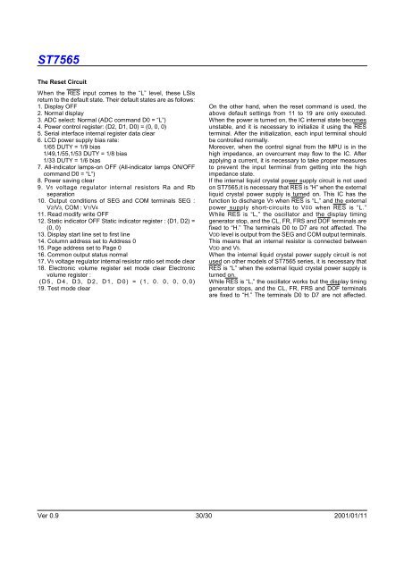
<strong>ST7565</strong>The Reset CircuitWhen the RES input <strong>com</strong>es to the “L” level, these LSIsreturn to the default state. Their default states are as follows:1. Display OFF2. Normal display3. ADC select: Normal (ADC <strong>com</strong>mand D0 = “L”)4. Power control register: (D2, D1, D0) = (0, 0, 0)5. Serial interface internal register data clear6. LCD power supply bias rate:1/65 DUTY = 1/9 bias1/49,1/55,1/53 DUTY = 1/8 bias1/33 DUTY = 1/6 bias7. All-indicator lamps-on OFF (All-indicator lamps ON/OFF<strong>com</strong>mand D0 = “L”)8. Power saving clear9. V5 voltage regulator internal resistors Ra and Rbseparation10. Output conditions of SEG and COM terminals SEG :V2/V3, COM : V1/V411. Read modify write OFF12. Static indicator OFF Static indicator register : (D1, D2) =(0, 0)13. Display start line set to first line14. Column address set to Address 015. Page address set to Page 016. Common output status normal17. V5 voltage regulator internal resistor ratio set mode clear18. Electronic volume register set mode clear Electronicvolume register :(D5, D4, D3, D2, D1, D0) = (1, 0. 0, 0, 0,0)19. Test mode clearOn the other hand, when the reset <strong>com</strong>mand is used, theabove default settings from 11 to 19 are only executed.When the power is turned on, the IC internal state be<strong>com</strong>esunstable, and it is necessary to initialize it using the RESterminal. After the initialization, each input terminal shouldbe controlled normally.Moreover, when the control signal from the MPU is in thehigh impedance, an overcurrent may flow to the IC. Afterapplying a current, it is necessary to take proper measuresto prevent the input terminal from getting into the highimpedance state.If the internal liquid crystal power supply circuit is not usedon <strong>ST7565</strong>,it is necessary that RES is “H” when the externalliquid crystal power supply is turned on. This IC has thefunction to discharge V5 when RES is “L,” and the externalpower supply short-circuits to VDD when RES is “L.”While RES is “L,” the oscillator and the display timinggenerator stop, and the CL, FR, FRS and DOF terminals arefixed to “H.” The terminals D0 to D7 are not affected. TheVDD level is output from the SEG and COM output terminals.This means that an internal resistor is connected betweenVDD and V5.When the internal liquid crystal power supply circuit is notused on other models of <strong>ST7565</strong> series, it is necessary thatRES is “L” when the external liquid crystal power supply isturned on.While RES is “L,” the oscillator works but the display timinggenerator stops, and the CL, FR, FRS and DOF terminalsare fixed to “H.” The terminals D0 to D7 are not affected.Ver 0.9 30/30 2001/01/11


