You also want an ePaper? Increase the reach of your titles
YUMPU automatically turns print PDFs into web optimized ePapers that Google loves.
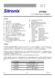
<strong>ST7565</strong>The Serial InterfaceWhen the serial interface has been selected (P/S = “L”) thenwhen the chip is in active state (CS1 = “L” and CS2 = “H”) theserial data input (SI) and the serial clock input (SCL) can bereceived. The serial data is read from the serial data inputpin in the rising edge of the serial clocks D7, D6 through D0,in this order. This data is converted to 8 bits parallel data inthe rising edge of the eighth serial clock for the processing.The A0 input is used to determine whether or the serial datainput is display data or <strong>com</strong>mand data; when A0 = “H”, thedata is display data, and when A0 = “L” then the data is<strong>com</strong>mand data. The A0 input is read and used for detectionevery 8th rising edge of the serial clock after the chipbe<strong>com</strong>es active. Figure 1 is a serial interface signal chart.Figure 1* When the chip is not active, the shift registers and the counter are reset to their initial states.* Reading is not possible while in serial interface mode.* Caution is required on the SCL signal when it <strong>com</strong>es to line-end reflections and external noise. We re<strong>com</strong>mend that operationbe rechecked on the actual equipment.The Chip SelectThe <strong>ST7565</strong> have two chip select terminals: CS1 and CS2.The MPU interface or the serial interface isenabled only when CS1 = “L” and CS2 = “H”.When the chip select is inactive, D0 to D7 enter a highimpedance state, and the A0, RD, and WR inputs areinactive. When the serial interface is selected, the shiftregister and the counter are reset.The Accessing the Display Data RAM and the Internal RegistersData transfer at a higher speed is ensured since the MPU isrequired to satisfy the cycle time (tCYC) requirement alone inaccessing the <strong>ST7565</strong>. Wait time may not be considered.And, in the <strong>ST7565</strong>, each time data is sent from the MPU, atype of pipeline process between LSIs is performed throughthe bus holder attached to the internal data bus. Internaldata bus.For example, when the MPU writes data to the display dataRAM, once the data is stored in the bus holder, then it iswritten to the display data RAM before the next data writecycle. Moreover, when the MPU reads the display data RAM,the first data read cycle (dummy) stores the read data in thebus holder, and then the data is read from the bus holder tothe system bus at the next data read cycle.There is a certain restriction in the read sequence of thedisplay data RAM. Please be advised that data of thespecified address is not generated by the read instructionissued immediately after the address setup. This data isgenerated in data read of the second time. Thus, a dummyread is required whenever the address setupor write cycle operation is conducted.This relationship is shown in Figure 2.Ver 0.9 13/13 2001/01/11