

Miller Park: Pivot Bearing Replacement - Heavy Movable Structures ...
Miller Park: Pivot Bearing Replacement - Heavy Movable Structures ...
Miller Park: Pivot Bearing Replacement - Heavy Movable Structures ...

You also want an ePaper? Increase the reach of your titles
YUMPU automatically turns print PDFs into web optimized ePapers that Google loves.
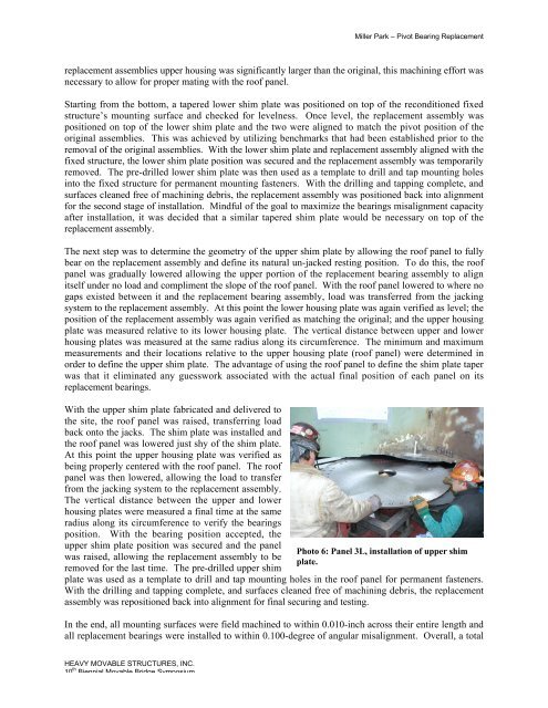
<strong>Miller</strong> <strong>Park</strong> – <strong>Pivot</strong> <strong>Bearing</strong> <strong>Replacement</strong>replacement assemblies upper housing was significantly larger than the original, this machining effort wasnecessary to allow for proper mating with the roof panel.Starting from the bottom, a tapered lower shim plate was positioned on top of the reconditioned fixedstructure’s mounting surface and checked for levelness. Once level, the replacement assembly waspositioned on top of the lower shim plate and the two were aligned to match the pivot position of theoriginal assemblies. This was achieved by utilizing benchmarks that had been established prior to theremoval of the original assemblies. With the lower shim plate and replacement assembly aligned with thefixed structure, the lower shim plate position was secured and the replacement assembly was temporarilyremoved. The pre-drilled lower shim plate was then used as a template to drill and tap mounting holesinto the fixed structure for permanent mounting fasteners. With the drilling and tapping complete, andsurfaces cleaned free of machining debris, the replacement assembly was positioned back into alignmentfor the second stage of installation. Mindful of the goal to maximize the bearings misalignment capacityafter installation, it was decided that a similar tapered shim plate would be necessary on top of thereplacement assembly.The next step was to determine the geometry of the upper shim plate by allowing the roof panel to fullybear on the replacement assembly and define its natural un-jacked resting position. To do this, the roofpanel was gradually lowered allowing the upper portion of the replacement bearing assembly to alignitself under no load and compliment the slope of the roof panel. With the roof panel lowered to where nogaps existed between it and the replacement bearing assembly, load was transferred from the jackingsystem to the replacement assembly. At this point the lower housing plate was again verified as level; theposition of the replacement assembly was again verified as matching the original; and the upper housingplate was measured relative to its lower housing plate. The vertical distance between upper and lowerhousing plates was measured at the same radius along its circumference. The minimum and maximummeasurements and their locations relative to the upper housing plate (roof panel) were determined inorder to define the upper shim plate. The advantage of using the roof panel to define the shim plate taperwas that it eliminated any guesswork associated with the actual final position of each panel on itsreplacement bearings.With the upper shim plate fabricated and delivered tothe site, the roof panel was raised, transferring loadback onto the jacks. The shim plate was installed andthe roof panel was lowered just shy of the shim plate.At this point the upper housing plate was verified asbeing properly centered with the roof panel. The roofpanel was then lowered, allowing the load to transferfrom the jacking system to the replacement assembly.The vertical distance between the upper and lowerhousing plates were measured a final time at the sameradius along its circumference to verify the bearingsposition. With the bearing position accepted, theupper shim plate position was secured and the panelwas raised, allowing the replacement assembly to beremoved for the last time. The pre-drilled upper shimPhoto 6: Panel 3L, installation of upper shimplate.plate was used as a template to drill and tap mounting holes in the roof panel for permanent fasteners.With the drilling and tapping complete, and surfaces cleaned free of machining debris, the replacementassembly was repositioned back into alignment for final securing and testing.In the end, all mounting surfaces were field machined to within 0.010-inch across their entire length andall replacement bearings were installed to within 0.100-degree of angular misalignment. Overall, a totalHEAVY MOVABLE STRUCTURES, INC.10 th Biennial <strong>Movable</strong> Bridge Symposium


