

LM45 SOT-23 Precision Centigrade Temperature Sensors - Micropik
LM45 SOT-23 Precision Centigrade Temperature Sensors - Micropik
LM45 SOT-23 Precision Centigrade Temperature Sensors - Micropik
- No tags were found...

Create successful ePaper yourself
Turn your PDF publications into a flip-book with our unique Google optimized e-Paper software.
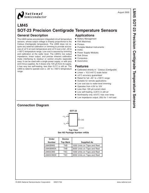
<strong>LM45</strong><strong>SOT</strong>-<strong>23</strong> <strong>Precision</strong> <strong>Centigrade</strong> <strong>Temperature</strong> <strong>Sensors</strong>General DescriptionThe <strong>LM45</strong> series are precision integrated-circuit temperaturesensors, whose output voltage is linearly proportional to theCelsius (<strong>Centigrade</strong>) temperature. The <strong>LM45</strong> does not requireany external calibration or trimming to provide accuraciesof ±2˚C at room temperature and ±3˚C over a full −20 to+100˚C temperature range. Low cost is assured by trimmingand calibration at the wafer level. The <strong>LM45</strong>’s low outputimpedance, linear output, and precise inherent calibrationmake interfacing to readout or control circuitry especiallyeasy. It can be used with a single power supply, or with plusand minus supplies. As it draws only 120 µA from its supply,it has very low self-heating, less than 0.2˚C in still air. The<strong>LM45</strong> is rated to operate over a −20˚ to +100˚C temperaturerange.Connection DiagramApplicationsn Battery Managementn FAX Machinesn Printersn Portable Medical Instrumentsn HVACn Power Supply Modulesn Disk Drivesn Computersn AutomotiveFeaturesn Calibrated directly in ˚ Celsius (<strong>Centigrade</strong>)n Linear + 10.0 mV/˚C scale factorn ±3˚C accuracy guaranteedn Rated for full −20˚ to +100˚C rangen Suitable for remote applicationsn Low cost due to wafer-level trimmingn Operates from 4.0V to 10Vn Less than 120 µA current drainn Low self-heating, 0.20˚C in still airn Nonlinearity only ±0.8˚C max over tempn Low impedance output, 20Ω for 1 mA loadAugust 2005<strong>LM45</strong> <strong>SOT</strong>-<strong>23</strong> <strong>Precision</strong> <strong>Centigrade</strong> <strong>Temperature</strong> <strong>Sensors</strong><strong>SOT</strong>-<strong>23</strong>01175401Top ViewSee NS Package Number mf03aOrder DeviceNumber Top Mark Supplied As<strong>LM45</strong>BIM3 T4B 1000 Units on Tape and Reel<strong>LM45</strong>BIM3X T4B 3000 Units on Tape and Reel<strong>LM45</strong>CIM3 T4C 1000 Units on Tape and Reel<strong>LM45</strong>CIM3X T4C 3000 Units on Tape and Reel© 2005 National Semiconductor Corporation DS011754 www.national.com
<strong>LM45</strong>Typical Applications01175403FIGURE 1. Basic <strong>Centigrade</strong> <strong>Temperature</strong>Sensor (+2.5˚C to +100˚C)Choose R 1 =−V S /50 µAV OUT = (10 mV/˚C x Temp ˚C)V OUT = +1,000 mV at +100˚C= +250 mV at +25˚C= −200 mV at −20˚C01175404FIGURE 2. Full-Range <strong>Centigrade</strong><strong>Temperature</strong> Sensor (−20˚C to +100˚C)www.national.com 2
Absolute Maximum Ratings (Note 1)Operating Ratings (Note 1)<strong>LM45</strong>Supply VoltageOutput VoltageOutput CurrentStorage <strong>Temperature</strong>ESD Susceptibility (Note 3):Human Body ModelMachine Model+12V to −0.2V+V S + 0.6V to−1.0V10 mA−65˚C to +150˚C2000V250VSpecified <strong>Temperature</strong> Range(Note 4)T MIN to T MAX<strong>LM45</strong>B, <strong>LM45</strong>C−20˚C to +100˚COperating <strong>Temperature</strong> Range<strong>LM45</strong>B, <strong>LM45</strong>C−40˚C to +125˚CSupply Voltage Range (+V S ) +4.0V to +10VSoldering process must comply with National Semiconductor’sReflow <strong>Temperature</strong> Profile specifications. Refer towww.national.com/packaging. (Note 2)Electrical CharacteristicsUnless otherwise noted, these specifications apply for +V S = +5Vdc and I LOAD = +50 µA, in the circuit of Figure 2. These specificationsalso apply from +2.5˚C to T MAX in the circuit of Figure 1 for +V S = +5Vdc. Boldface limits apply for T A =T J =T MINto T MAX ; all other limits T A =T J = +25˚C, unless otherwise noted.Parameter Conditions <strong>LM45</strong>B <strong>LM45</strong>C UnitsTypical Limit Typical Limit (Limit)(Note 5) (Note 5)Accuracy T A =+25˚C ±2.0 ±3.0 ˚C (max)(Note 6) T A =T MAX±3.0 ±4.0 ˚C (max)T A =T MIN±3.0 ±4.0 ˚C (max)Nonlinearity T MIN ≤T A ≤T MAX±0.8 ±0.8 ˚C (max)(Note 7)Sensor Gain T MIN ≤T A ≤T MAX +9.7 +9.7 mV/˚C (min)(Average Slope) +10.3 +10.3 mV/˚C (max)Load Regulation (Note 8) 0≤I L ≤ +1 mA ±35 ±35 mV/mA (max)Line Regulation +4.0V≤+V S ≤+10V ±0.80 ±0.80 mV/V (max)(Note 8) ±1.2 ±1.2 mV/V (max)Quiescent Current +4.0V≤+V S ≤+10V, +25˚C 120 120 µA (max)(Note 9) +4.0V≤+V S ≤+10V 160 160 µA (max)Change of Quiescent 4.0V≤+V S ≤10V 2.0 2.0 µA (max)Current (Note 9)<strong>Temperature</strong> Coefficient +2.0 +2.0 µA/˚Cof Quiescent CurrentMinimum <strong>Temperature</strong> In circuit of +2.5 +2.5 ˚C (min)for Rated Accuracy Figure 1, I L =0Long Term Stability (Note 10) T J =T MAX , for 1000 hours ±0.12 ±0.12 ˚CNote 1: Absolute Maximum Ratings indicate limits beyond which damage to the device may occur. DC and AC electrical specifications do not apply when operatingthe device beyond its rated operating conditions.Note 2: Reflow temperature profiles are different for lead-free and non-lead-free packages.Note 3: Human body model, 100 pF discharged through a 1.5 kΩ resistor. Machine model, 200 pF discharged directly into each pin.Note 4: Thermal resistance of the <strong>SOT</strong>-<strong>23</strong> package is 260˚C/W, junction to ambient when attached to a printed circuit board with 2 oz. foil as shown in Figure 3.Note 5: Limits are guaranteed to National’s AOQL (Average Outgoing Quality Level).Note 6: Accuracy is defined as the error between the output voltage and 10 mv/˚C times the device’s case temperature, at specified conditions of voltage, current,and temperature (expressed in ˚C).Note 7: Nonlinearity is defined as the deviation of the output-voltage-versus-temperature curve from the best-fit straight line, over the device’s rated temperaturerange.Note 8: Regulation is measured at constant junction temperature, using pulse testing with a low duty cycle. Changes in output due to heating effects can becomputed by multiplying the internal dissipation by the thermal resistance.Note 9: Quiescent current is measured using the circuit of Figure 1.Note 10: For best long-term stability, any precision circuit will give best results if the unit is aged at a warm temperature, and/or temperature cycled for at least 46hours before long-term life test begins. This is especially true when a small (Surface-Mount) part is wave-soldered; allow time for stress relaxation to occur.3www.national.com
<strong>LM45</strong>Typical Performance Characteristics To generate these curves the <strong>LM45</strong> was mounted to a printedcircuit board as shown in Figure 3.Thermal ResistanceJunction to AirThermal Time Constant01175424 01175425Thermal Response in Still Airwith Heat Sink (Figure 3)Thermal Responsein Stirred Oil Bathwith Heat Sink0117542601175427Start-Up Voltagevs <strong>Temperature</strong>Quiescent Currentvs <strong>Temperature</strong>(In Circuit of Figure 1)01175428 01175429www.national.com 4
Typical Performance Characteristics To generate these curves the <strong>LM45</strong> was mounted to a printedcircuit board as shown in Figure 3. (Continued)<strong>LM45</strong>Quiescent Currentvs <strong>Temperature</strong>(In Circuit of Figure 2)Accuracy vs <strong>Temperature</strong>(Guaranteed)01175430 01175431Noise VoltageSupply Voltagevs Supply Current01175432 01175433Start-Up Response011754345www.national.com
<strong>LM45</strong>Printed Circuit Board011754<strong>23</strong>FIGURE 3. Printed Circuit Board Used for Heat Sink to Generate All Curves.1⁄2" Square Printed Circuit Board with 2 oz. Foil or SimilarApplicationsThe <strong>LM45</strong> can be applied easily in the same way as otherintegrated-circuit temperature sensors. It can be glued orcemented to a surface and its temperature will be withinabout 0.2˚C of the surface temperature.This presumes that the ambient air temperature is almost thesame as the surface temperature; if the air temperature weremuch higher or lower than the surface temperature, theactual temperature of the <strong>LM45</strong> die would be at an intermediatetemperature between the surface temperature and theair temperature.To ensure good thermal conductivity the backside of the<strong>LM45</strong> die is directly attached to the GND pin. The lands andtraces to the <strong>LM45</strong> will, of course, be part of the printedcircuit board, which is the object whose temperature is beingmeasured. These printed circuit board lands and traces willnot cause the <strong>LM45</strong>s temperature to deviate from the desiredtemperature.Alternatively, the <strong>LM45</strong> can be mounted inside a sealed-endmetal tube, and can then be dipped into a bath or screwedinto a threaded hole in a tank. As with any IC, the <strong>LM45</strong> andaccompanying wiring and circuits must be kept insulated anddry, to avoid leakage and corrosion. This is especially true ifthe circuit may operate at cold temperatures where condensationcan occur. Printed-circuit coatings and varnishes suchas Humiseal and epoxy paints or dips are often used toinsure that moisture cannot corrode the <strong>LM45</strong> or its connections.<strong>Temperature</strong> Rise of <strong>LM45</strong> Due to Self-Heating (ThermalResistance)<strong>SOT</strong>-<strong>23</strong><strong>SOT</strong>-<strong>23</strong>no heat sink* small heat fin**Still air 450˚C/W 260˚C/WMoving air180˚C/W* Part soldered to 30 gauge wire.** Heat sink used is 1 ⁄2” square printed circuit board with 2 oz. foil with partattached as shown in Figure 3.www.national.com 6
Typical Applications<strong>LM45</strong>CAPACITIVE LOADSLike most micropower circuits, the <strong>LM45</strong> has a limited abilityto drive heavy capacitive loads. The <strong>LM45</strong> by itself is able todrive 500 pF without special precautions. If heavier loads areanticipated, it is easy to isolate or decouple the load with aresistor; see Figure 4. Or you can improve the tolerance ofcapacitance with a series R-C damper from output toground; see Figure 5.Any linear circuit connected to wires in a hostile environmentcan have its performance affected adversely by intense electromagneticsources such as relays, radio transmitters, motorswith arcing brushes, SCR transients, etc, as its wiringcan act as a receiving antenna and its internal junctions canact as rectifiers. For best results in such cases, a bypasscapacitor from V IN to ground and a series R-C damper suchas 75Ω in series with 0.2 or 1 µF from output to ground, asshown in Figure 5, are often useful.01175414FIGURE 7. 4-to-20 mA Current Source (0˚C to +100˚C)01175408FIGURE 4. <strong>LM45</strong> with Decoupling from Capacitive Load0117540901175415FIGURE 5. <strong>LM45</strong> with R-C DamperFIGURE 8. Fahrenheit Thermometer01175412FIGURE 6. <strong>Temperature</strong> Sensor,Single Supply, −20˚C to +100˚C01175416FIGURE 9. <strong>Centigrade</strong> Thermometer (Analog Meter)7www.national.com
<strong>LM45</strong>Typical Applications (Continued)01175417FIGURE 10. Expanded Scale Thermometer(50˚ to 80˚ Fahrenheit, for Example Shown)01175418FIGURE 11. <strong>Temperature</strong> To Digital Converter (Serial Output) (+128˚C Full Scale)01175419FIGURE 12. <strong>Temperature</strong> To Digital Converter (Parallel TRI-STATE ® Outputs forStandard Data Bus to µP Interface) (128˚C Full Scale)www.national.com 8
Typical Applications (Continued)<strong>LM45</strong>* =1% or 2% film resistor-Trim R B for V B =3.075V-Trim R C for V C =1.955V01175420-Trim R A for V A =0.075V + 100mV/˚C x T ambient-Example, V A =2.275V at 22˚CFIGURE 13. Bar-Graph <strong>Temperature</strong> Display (Dot Mode)01175421FIGURE 14. <strong>LM45</strong> With Voltage-To-Frequency Converter And Isolated Output(2.5˚C to +100˚C; 25 Hz to 1000 Hz)9www.national.com
<strong>LM45</strong>Block Diagram01175422www.national.com 10
Physical Dimensions inches (millimeters) unless otherwise noted<strong>SOT</strong>-<strong>23</strong> Molded Small Outline Transistor Package (M3)Order Number <strong>LM45</strong>BIM3, <strong>LM45</strong>BIM3X, <strong>LM45</strong>CIM3 or <strong>LM45</strong>CIM3XNS Package Number mf03a<strong>LM45</strong> <strong>SOT</strong>-<strong>23</strong> <strong>Precision</strong> <strong>Centigrade</strong> <strong>Temperature</strong> <strong>Sensors</strong>National does not assume any responsibility for use of any circuitry described, no circuit patent licenses are implied and National reservesthe right at any time without notice to change said circuitry and specifications.For the most current product information visit us at www.national.com.LIFE SUPPORT POLICYNATIONAL’S PRODUCTS ARE NOT AUTHORIZED FOR USE AS CRITICAL COMPONENTS IN LIFE SUPPORT DEVICES OR SYSTEMSWITHOUT THE EXPRESS WRITTEN APPROVAL OF THE PRESIDENT AND GENERAL COUNSEL OF NATIONAL SEMICONDUCTORCORPORATION. As used herein:1. Life support devices or systems are devices or systemswhich, (a) are intended for surgical implant into the body, or(b) support or sustain life, and whose failure to perform whenproperly used in accordance with instructions for useprovided in the labeling, can be reasonably expected to resultin a significant injury to the user.2. A critical component is any component of a life supportdevice or system whose failure to perform can be reasonablyexpected to cause the failure of the life support device orsystem, or to affect its safety or effectiveness.BANNED SUBSTANCE COMPLIANCENational Semiconductor manufactures products and uses packing materials that meet the provisions of the Customer ProductsStewardship Specification (CSP-9-111C2) and the Banned Substances and Materials of Interest Specification (CSP-9-111S2) and containno ‘‘Banned Substances’’ as defined in CSP-9-111S2.Leadfree products are RoHS compliant.National SemiconductorAmericas CustomerSupport CenterEmail: new.feedback@nsc.comTel: 1-800-272-9959www.national.comNational SemiconductorEurope Customer Support CenterFax: +49 (0) 180-530 85 86Email: europe.support@nsc.comDeutsch Tel: +49 (0) 69 9508 6208English Tel: +44 (0) 870 24 0 2171Français Tel: +33 (0) 1 41 91 8790National SemiconductorAsia Pacific CustomerSupport CenterEmail: ap.support@nsc.comNational SemiconductorJapan Customer Support CenterFax: 81-3-5639-7507Email: jpn.feedback@nsc.comTel: 81-3-5639-7560


