Grid Job Routing Algorithms - Phosphorus
Grid Job Routing Algorithms - Phosphorus
Grid Job Routing Algorithms - Phosphorus

Create successful ePaper yourself
Turn your PDF publications into a flip-book with our unique Google optimized e-Paper software.
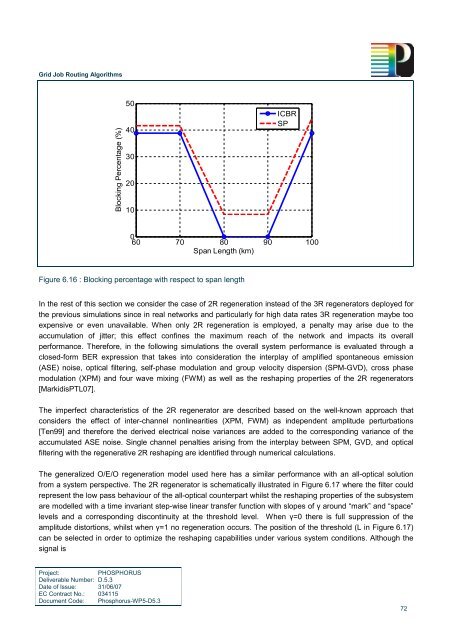
<strong>Grid</strong> <strong>Job</strong> <strong>Routing</strong> <strong>Algorithms</strong>Blocking Percentage (%)5040302010ICBRSP060 70 80 90 100Span Length (km)Figure 6.16 : Blocking percentage with respect to span lengthIn the rest of this section we consider the case of 2R regeneration instead of the 3R regenerators deployed forthe previous simulations since in real networks and particularly for high data rates 3R regeneration maybe tooexpensive or even unavailable. When only 2R regeneration is employed, a penalty may arise due to theaccumulation of jitter; this effect confines the maximum reach of the network and impacts its overallperformance. Therefore, in the following simulations the overall system performance is evaluated through aclosed-form BER expression that takes into consideration the interplay of amplified spontaneous emission(ASE) noise, optical filtering, self-phase modulation and group velocity dispersion (SPM-GVD), cross phasemodulation (XPM) and four wave mixing (FWM) as well as the reshaping properties of the 2R regenerators[MarkidisPTL07].The imperfect characteristics of the 2R regenerator are described based on the well-known approach thatconsiders the effect of inter-channel nonlinearities (XPM, FWM) as independent amplitude perturbations[Ten99] and therefore the derived electrical noise variances are added to the corresponding variance of theaccumulated ASE noise. Single channel penalties arising from the interplay between SPM, GVD, and opticalfiltering with the regenerative 2R reshaping are identified through numerical calculations.The generalized O/E/O regeneration model used here has a similar performance with an all-optical solutionfrom a system perspective. The 2R regenerator is schematically illustrated in Figure 6.17 where the filter couldrepresent the low pass behaviour of the all-optical counterpart whilst the reshaping properties of the subsystemare modelled with a time invariant step-wise linear transfer function with slopes of γ around “mark” and “space”levels and a corresponding discontinuity at the threshold level. When γ=0 there is full suppression of theamplitude distortions, whilst when γ=1 no regeneration occurs. The position of the threshold (L in Figure 6.17)can be selected in order to optimize the reshaping capabilities under various system conditions. Although thesignal isProject:PHOSPHORUSDeliverable Number: D.5.3Date of Issue: 31/06/07EC Contract No.: 034115Document Code: <strong>Phosphorus</strong>-WP5-D5.372