beaver
beaver
beaver
- No tags were found...

You also want an ePaper? Increase the reach of your titles
YUMPU automatically turns print PDFs into web optimized ePapers that Google loves.
BEAVERHANDY AUTOMATIC GAS CUTTING MACHINEKOIKE SANSO KOGYO CO.,LTD.
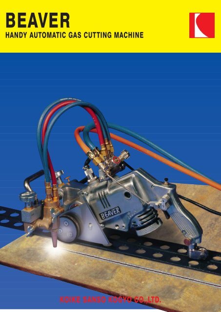
The BEAVER is a portable automatic gas cutting machine of a unique structure, which wins success in two different functions– that is running stability of straight line cutting and tracing accuracy of curved line cutting.Moreover with an optional auto-stop function, the operator does not need any more to watch the rail ending point, as the autostopfunction acts to stop the running operation and gas supply at the rail end. Try our the BEAVER, and you will see why wecall it unique, how well it works, how easily it can be operated.Best cutting of straight and curved line by shifting guidewheelFor the straight and curved line cutting, the point is thedistance between the guide wheel and the driving wheel.On straight line cutting, the longer the distance is, thebetter the running stability is: while on curved line cutting,the shorter the distance is, the better the curve tracingaccuracy is. Therefore, as its unique structure, theBEAVER resolves the problem by shifting the guide wheeland succeeds in getting both running stability op straightline cutting and tracing accuracy of curved line cutting.On curved line cutting, attach the guide wheel to the front,while on automatic straight line cutting, attach it to therear.Easy to operateThe grip of the BEAVER is of a pistol shape and fitsoperator’s hand well. A trigger type clutch a speed controldial under the clotch are operated by a index finger. Thethumb operates a power switch and jet oxygen lever. Thusthe operator can control all functions by a single hand.Standing type – needs little space to keepWhen BEAVER is not operated, it can be stood with itsgrip upward. Therefore BEAVER saves the space to keepit, and makes it easy to clean the tip (see photo 2).specificationsCutting thickness 3~150 mm (1/8~6")Cutting speed 50~1.000 mm (2~39")Circle cutting radius 30~350 mm(w. optional equipment) (1-3/16~13-1/2")Cutting shapeI.V.Speed changeVariable resistorPower42/110/220V ACMachine length 430 mm (16-15/16")Weight9 kg (19,8 lbs)accessoriesPower cord 5m (196") 1 pc (Direct-linkedpower cord is possible)Tip 102HC (for acetylen) # 0-1-2or 106HC (for LPG) 1 pc EACHTip cleaner1 pcLighter1 pcTool set1 pcHose3 pcs (From torch to valve)Rail1 pcoptional equipmentCircle cutting AttachmentSpare parts kit1 set1 set123104598671. Torch2. Drive wheel3. Heat shield4. Guide wheel5. Speed control dial6. Clutch lever7. Grip8. Power switch9. Jet oxygen lever10.Gas distributorPhoto 1 Photo 2KOIKE SANSOKOGYO CO.,LTD.International DivisionTotal system supplier of welding and cutting KOIKE INTERNATIONAL GROUP1-1, Ojima 9-chome,Koto-ku, Tokyo,136-0072 Japan.Tel: +81 (0)3 - 3685 9111Fax: +81 (0)3 - 3685 1990www.koikeox.co.jpKOIKE ARONSON, INC.635 West Main Street,Arcade, NY14009, USA.Tel: +1 (0)716 - 492 2400Fax: +1 (0)716 - 457 3517www.koike.comSpecifications shown herein are subject to change without noticeKOIKE KOREAENGINEERING CO.,LTD.1318-26, Daekwang-Dong,Kimcheon-City,Kyoung Sangbuk-Do, Korea.Tel: +82 (0)547 - 39 3711Fax: +82 (0)547 - 39 3713KOIKE EUROPE B.V.Grote Tocht 19,1507 CG Zaandam, Holland.Tel: +31 (0)75 - 612 72 27Fax: +31 (0)75 - 670 22 71www.koike.nlKOIKE FRANCE S.A.R.L.Zae ‘Les dix Muids” EspaceBP 58, 29582 Marly CedexTel: +33 (0)3 - 2730 4343Fax: +33 (0)3 - 2730 1250
BEAVERCONTENTS1 Safety information ......................................................................................... 51.1 Introduction ............................................................................................ 51.2 General machine safety precautions ..................................................... 51.2.1 Machine safety ............................................................................ 51.2.2 Safety clothing ............................................................................. 61.2.3 Electrical system precautions ...................................................... 61.2.4 Maintenance and inspection precautions .................................... 61.3 General Gas cutting safety precautions ................................................ 71.3.1 Prevention of explosion ............................................................... 71.3.2 Pressure regulator safety precautions ......................................... 71.3.3 High pressure gas cylinder safety precautions ............................ 71.3.4 Safety precautions for hoses ....................................................... 71.3.5 Safety precautions for fire ........................................................... 81.3.6 Safety precautions for skin burns ................................................ 81.4 Operating and handling safety precautions ........................................... 92 Locations of safety labels ............................................................................ 113 Outline of machine ...................................................................................... 133.1 Features of machine ............................................................................ 133.2 Name and function of each section ..................................................... 133.3 Specifications ...................................................................................... 154 Preparation for operation ............................................................................ 174.1 Contents of package ............................................................................ 174.2 Assembly ............................................................................................. 174.2.1 Connecting the gas distributor to the machine .......................... 174.2.2 Connecting the torch holder to the machine .............................. 184.2.3 Attaching the torch to the torch holder ...................................... 184.2.4 Linking the gas distributor with the torch ................................... 184.2.5 Attaching the carrier bar ............................................................ 194.2.6 Attaching the primary hose to the gas distributor ...................... 194.3 Preparation for operation ..................................................................... 204.3.1 Connecting the power cable ...................................................... 204.3.2 Connecting the gas supply hose ............................................... 204.3.3 Connecting the tip ..................................................................... 205 Cutting Operation ........................................................................................ 215.1 Safety measures prior to operation ..................................................... 215.1.1 Selection of tip ........................................................................... 215.1.2 Operation of running direction changeover switch .................... 215.2 Ignition and flame adjustment .............................................................. 215.3 Cutting and piercing method ................................................................ 225.4 Procedures for starting cutting operation and extinguishing the flame 231
HANDY AUTO5.5 Safety measures against backfire and flashback ................................ 235.5.1 Prevention of backfire ................................................................ 235.5.2 Prevention of flashback ............................................................. 245.6 Cutting operation ................................................................................. 245.6.1 Straight cutting .......................................................................... 245.6.2 Manual guide cutting ................................................................. 255.6.3 Ordinary circle cutting ................................................................ 265.6.4 Optional circle cutting ................................................................ 275.6.5 Bevel cutting .............................................................................. 295.7 Optional equipment ............................................................................. 295.7.1 Circle cutting attachment (stock no. 33353) .............................. 295.7.2 Auto stop (stock no. 33364) ...................................................... 295.7.3 Straight rail ................................................................................ 305.7.4 Angle tracing roller .................................................................... 306 Maintenance and inspection ....................................................................... 316.1 Disassembly ........................................................................................ 316.1.1 Maintenance of the electrical equipment ................................... 316.1.2 Maintenance of the gear case ................................................... 316.1.3 Maintenance of the drive motor and the reduction gear ............ 326.2 Periodical inspection and maintenance ............................................... 336.2.1 Daily .......................................................................................... 336.2.2 Monthly or every 300 hours ....................................................... 336.2.3 Every three months or 1000 hours ............................................ 346.2.4 Every six months ....................................................................... 347 Troubleshooting .......................................................................................... 358 Wiring diagram and assembly drawing ....................................................... 399 Parts list ...................................................................................................... 419.1 Main units ...................................................................................... 419.2 Gear case ............................................................................................ 439.3 Torch holder and gas distributor .......................................................... 469.4 Circle cutting attachment ..................................................................... 489.5 Auto stop ............................................................................................. 509.6 Angle tracing roller .............................................................................. 5210 Cutting Data ................................................................................................ 532
BEAVERPREFACEIntroductionThank you very much for purchasing this product. This manual is intendedfor operators and maintenance personnel. Read the operation manualthoroughly to ensure correct, safe and effective use of the machine.Make sure you read, understand and take all the necessary safetyprecautions.Safety precautionsThis product is designed to be safe, but it can cause serious accidents ifnot operated correctly. Those who operate and repair this machine mustread this manual thoroughly before operating, inspecting and maintainingthe machine. Keep the manual near the machine so that anyone whooperates, inspects or maintains the machine can refer to it if necessary.• Do not use the machine carelessly without following the instructionsin the manual.• Use the machine only after you completely understood the contentsof the manual.• If an explanation in the manual is difficult to understand, contact ourcompany or sales service office.• Keep the manual near by at all times and read it as many times asnecessary for a complete understanding.• If the manual becomes lost or damaged, place an order with ourcompany or sales service office for a new one.• When transferring the machine to a new owner, be sure to hand overthis instruction manual as well.Qualifications for machine operatorOperators and repair staff of this machine must completely understandthe contents of the instruction manual and they must be qualified andeducated to handle this equipment.3
BEAVERExplanation of symbolsIn this manual safety signs (symbols) are used to indicate safetymessages and signal words to indicate the degree or level of hazard. Thesafety indicators are explained in the table below.Symbol Title MeaningSafety alert symbolThis symbol is applied to indicate generalcaution, warning and danger messages.Be careful not to get your fingerscaught.Possible injury to fingers if caught in theinsertion point.Caution: Electric shock!Possible electric shock under specialconditions.Ground this equipment.Operators must ground the equipment using thesafety grounding terminal.Caution against bursting.Possible bursting under certain conditions.Caution: Hot!Possible injury due to high temperature undercertain conditions.Caution: Ignition!Possible ignition under certain conditions.Pull out the power plug from the outlet.Operators must unplug the power plug from theoutlet when a failure occurs or when there is adanger of lightning.table 2 - 14
BEAVER1 Safety information1.1 IntroductionOperation, inspection, and maintenance that disregard the basic safetyrules cause many accidents. Carefully read, understand, and master thesafety measures and precautions described in this operation manual andon the machine before operating, inspecting, and maintaining themachine.The safety messages used in this manual are classified as indicated onthe machine safety labels.DangerIndicates an imminently hazardous situation which, if not avoided,will result in death or serious injury. The safety label on the machineis positioned at places that can cause injury or serious accident.WarningIndicates a potentially hazardous situation which, if not avoided,could result in death or serious injury. The safety label on themachine is positioned at places that could cause injury or seriousaccident.CautionIndicates a potentially hazardous situation which, if not avoided, mayresult in minor or moderate injury or machine damage.Note:Indicates an additional explanation for an element of information.1.2 General machine safety precautions1.2.1 Machine safety• The machine casing is mainly made of aluminum alloy to reduceweight. For this reason, be careful not to drop a heavy item on themachine, or not to drop the machine when carrying it, since the alloyis not designed to withstand such impact.• When mounting hoses to the torch and distributor, tighten the nutwith the attached wrench. After mounting, be sure to check there is5
BEAVERno gas leak with a detection liquid. If a gas leak is found, retightenthe nut firmly.• Never disassemble the machine other than during maintenance andinspection. Otherwise, malfunction will result.• Never remodel the machine. Remodeling is very dangerous.• Always turn the power off when not used.• Never use the machine outdoors when the weather is wet. This willcause failure of the machine and could cause a fatal accident by anelectric shock.1.2.2 Safety clothing• Be sure to wear protective gauntlets, goggles, helmet, and safetyshoes during operation.• Avoid operating the machine with wet clothes or hands in order toprevent electric shock.1.2.3 Electrical system precautions1 Be sure to check the input power voltage of the machine beforeoperation. The input power voltage should be in the range of ± 10%of the rated voltage. The machine should not be operated out of thisrange.2 The metal plugs are screw-threaded, therefore, fully tighten them sothat they will not come loose during operation.3 Stop operation and turn off the power in the following cases, andask a qualified electrician to repair the machine.a Broken or abraded cables.b When the machine has been in contact with water, or in case ofliquid damage to the machine.c Abnormal machine operation despite operating the machineaccording to the instruction manual.d Machine breakdown.e Poor machine performance that requires repair.4 Periodically inspect the electrical system.1.2.4 Maintenance and inspection precautions1 Ask a qualified electrician to perform repair and inspection service.2 Disconnect the power plug before inspecting and repairing themachine.3 Maintain the machine periodically.6
BEAVER1.3 General Gas cutting safety precautionsStrictly observe the safety rules and precautions to ensure the safety ofgas cutting operations. Operators and supervisors MUST keep safety inmind.1.3.1 Prevention of explosion1 Never cut pressurized cylinders or hermetically sealed containers.2 Ensure sufficient ventilation for gas cutting to prevent the air frombecoming stale.1.3.2 Pressure regulator safety precautions1 Before starting operation, check that all pressure regulators areoperating correctly.2 Ask a skilled repair engineer to perform maintenance and inspectionservice.3 Do not use pressure regulators from which gas is leaking, normalfunctioning pressure regulators.4 Do not use pressure regulators smeared with oil or grease.1.3.3 High pressure gas cylinder safety precautions1 Never use broken cylinders or cylinders from which gas is leaking.2 Install cylinders upright and take measures to prevent them fromfalling.3 Use cylinders only for specified purposes.4 Do not smear container valves with oil or grease.5 Install cylinders in a place free from heat, sparks, slag, and openflame.6 Contact the distributor if the container valves will not open. Neveruse a hammer, wrench, or other tools to forcibly open containervalves.1.3.4 Safety precautions for hoses1 Use the oxygen hose for the oxygen gas only.2 Replace cracked hoses or other hoses damaged by sparks, heat,unshielded fire, etc.3 Install hoses without twisting.4 To prevent breakage of hoses, take great care during operation andtransportation.5 Do not hold the hoses when moving the machine.6 Periodically check the hoses for damage, leakage, fatigue, loosejoints, etc. to ensure safety.7
BEAVER7 Cut hoses to the minimum possible length. Short hoses reduce hosedamage and pressure drop, as well as reduce the flow resistance.1.3.5 Safety precautions for fireTake safety precautions to prevent fire prior to gas cutting.Ignoring hot metal, sparks, and slag could cause a fire.1 Keep a fire extinguisher, fire extinguish sand, bucket full of water,etc. ready on the site where gas cutting is performed.2 Keep flammables away from the cutting area to avoid exposure tosparks.3 Always cool down steel plates that have become hot after cutting,as well as hot cut parts or scrap, before bringing them close toflammables.4 Never cut containers to which flammable materials are stuck.1.3.6 Safety precautions for skin burnsObserve the safety precautions to prevent skin burns. Ignoring heat,spatter, and sparks during operation could cause a fire or burned skin.1 Do not perform cutting near flammables. (Move flammables wellaway from the sparks).2 Do not cut containers filled with flammables.3 Do not keep lighters, matches and other flammables nearby.4 Flames from the torch will burn the skin. Keep your body away fromthe torch and tip and check the safety before operating the switchesand valves.5 Wear the correct protectors to protect your eyes and body.6 Correctly tighten the tip to prevent backfire (see paragraph 5.5)7 Check with soapsuds for any leakage from gas from the connectionpart of the distributor, hose and torch.Never use oil or grease on the connection of the oxygen pipe toavoid backfire which may lead to explosion.8 Be sure to check the following when igniting:a Always wear the required protectors (gauntlets, helmet, goggles,etc.)b Check for any obstacles, dangerous materials and flammablescnear or in the direction of cutting. Determine the gas pressure.The gas pressure must be within the appropriate range. (For thegas pressure, refer to the Cutting Data).9 The torch, tip and heat shield are heated to a very high temperature.Always wear gauntlets when handling them. Also the surface aftercutting is very hot so do not touch it even while wearing gauntlets.8
BEAVER1.4 Operating and handling safety precautions1 Mount and center the machine correctly and confirm correct motionbefore operation.2 Before connecting the power plug to the outlet, make sure that thepower switch is in the OFF position (or the normal / reversechangeover switch is in the stop position).3 Prior to operating the machine, check the safety of the surroundingsto avoid accidents.4 Never move the machine while the preheat flame is on.5 Take great care of spatters and dross when operating the machine ata high position. They may injure people below.6 Completely secure the casters with screws for cutting on the rail.7 Correctly fix the heat shield so that it will not touch the rail.8 Screw the horizontal bar with the screw on the gear case to preventthe bar from falling.9 When connecting rails, be careful not to get your hands or fingerscaught between them.10 Remove the machine from the rail when moving the rail.11 Be sure to hold the handle when carrying the machine.9
BEAVER10
BEAVER2 Locations of safety labelsSafety labels and other labels for correct operation are affixed to themachine. Carefully read the labels and follow the instructions on themwhen operating the machine.Never remove the labels. Keep them clean and legible at all times.NETWEIGHTKgBEAVERSERIAL NOV.ACMADE IN JAPANONOFFfigure 2 - 111
BEAVER12
BEAVER3 Outline of machine3.1 Features of machineBEAVER is a portable automatic gas cutting machine for straight linecutting and accurate curved line cutting. It is a multipurpose grip-typecutter.Thanks to an automatic stopper (option) and an attachment for improvedcutting accuracy, as well as the excellent operability that allows singlehandoperation, the machine can be used for many purposes.3.2 Name and function of each section13
BEAVER1. Grip handleThe grip handle is of the most idealshape for the one-hand operation.2. ON/OFF SwitchIt is handled by the thumb andfunctions to turn the power on.3. Jet Oxygen (JOX) lever.It is handled by the thumb and letthe cutting oxygen flow.4. Speed adjustment dial.Handled by the forefinger andadjust the cutting speed.5. Clutch Lever.Handled by the forefinger and letthe drive wheel run to move themachine.6. Guide WheelOn the straight line cutting, put theguide wheel underneath the griphandle. The distance between thedrive wheel and the guide wheelthus lengthens and the machinerunning becomes stable. On thecurved line cutting, leave it in theoriginal position. The distancebetween the drive wheel and theguide wheel is short to get a freecommand of the marking-offcutting.7. Drive WheelThe running speed is 50~100 mm/min.8. MotorCommutator motor 25W 9500r.p.m.9. Gas DistributorQuantity of the preheat Oxygen,Fuel Gas and Cutting Oxygen isregulated here.10. HoseThree hoses (for Preheat Oxygen,Fuel Gas, Cutting Oxygen) link thegas distribution valve with the torch.11. Cabtyre cord5 Meters in length.12. Gear boxThe running speed is adjusted toany point through the voltagecontrol by the variable resistor.13. Torch block holderIt is used to adjust the torchposition.0~45° on outward bevel cutting(The torch end inclines to the outerside, apart from the machine).0~30° on inward bevel cutting (Thetorch end inclines to the nearerpoint to the machine).Horizontal stroke of the torch - 50mmVertical stroke of the torch - 20 mm14. Torch holder15. TorchCutting thickness 5~100 mm16. HandleIt is used to manual guide on themarking-off cutting, to attach theoptional equipment' and also tocarry the machine.17. Heat ShieldA safe guard of the machine againstthe heat. The drive wheel has alsothe heat proof cover.14
BEAVER3.3 SpecificationsTotal weightMachine size:9 kg (incl. rail)450 mm x 250 mm x 235 mmPower supply: 220-110-42VAC ± 10%Speed control: Variable resistorCutting speed:Cutting thickness:50 - 1000 mm / min5 - 100 mmBevel angle: 0 - 45ºTip:Gas:102 HC (for acetylene) or 106 HC(for propane)Oxygen, acetylene or LPGOptions:Automatic stopperAttachment for circular cuttingAngle - tracing rollerStraight rail (1.8)15
BEAVER16
BEAVER4 Preparation for operation4.1 Contents of packageFirst, please check your unit to make sure it is complete. The following is alist of the parts you should receive.BodyGas distributorTorch holderTorchDistribution hose(3-piece set: 450L)Cabtyre cord (5M)Tip 102 HC (acetylene) or 106 HC(for propane) # 0, 1,2Tip cleanerScrewdriverSpanner (3 pcs.)Carbon brush1 set1 set1 set1 pc1 set1 pc1 pc each1 set1 pc1 set2 pc4.2 Assembly4.2.1 Connecting the gas distributor to the machine(Tool to use: screwdriver)There are two dove-tale grooves on the upper surface of the machine.1 Fix the distributor, with the screws and the nuts on it firmly into thegrooves.2 Tighten the nuts.It will be easier if the connecting bar is inserted in the JOX lever of thedistributor.17
BEAVER4.2.2 Connecting the torch holder to themachine(No tool to use)1 Insert the two crossbars from leftto right until the rack and thepinion engages each other.2 Put it forward by pinion handle.Note: When the pinion handle istoo heavy or too smooth, adjustthe movement by the bolt on theaxis under the crossbars.1. Adjusting boltfigure 4 - 14.2.3 Attaching the torch to the torchholder(No tool to use)1 Loosen the wing screw of the torch holder2 Insert the torch from the top. (Best position of the torch is approx. 10mm upper from where the torch is inserted fully.)3 Tighten the screw.4.2.4 Linking the gas distributor with the torch(Tool to use: wrench) Refer to figure 4 - 2.The inlet nipples of the torch are:LongMediumShortJOXPOXGAS (Left screw)The hoses of gas distributor are:Blue valve sideBlue valve sideRed valve sidePOX (RH screw)JOX (middle)GAS (Left screw)18
BEAVERConnect the JOX with JOX, POX with POX, GAS with GAS respectively.1. GAS hose2. JOX hose3. POX hose4. GAS (Fuel Gas)5. JOX (Cutting Oxygen)6. POX (Preheat Oxygen)4.2.5 Attaching the carrier bar(Tool to use: wrench)1 Loosen the hexagon bolt.2 Insert the handle as illustrated.Besides as a handle it can be used tohold the balance weight or to protectthe crossbars.figure 4 - 21. Hexagon bolt2. Carrier barfigure 4 - 34.2.6 Attaching the primary hose to the gas distributor• Oxygen hose• Gas hose19
BEAVER4.3 Preparation for operation4.3.1 Connecting the power cableCautionBefore connection, check that there is no foreign substances or dust.1 Connect the power cable to the body.2 Fully tighten the screw-threaded metal plugs, so that they will notcome loose during operation.4.3.2 Connecting the gas supply hose1 Connect the respective gas supply hoses to the primary hose.2 Securely tighten the joints and check there is no gas leak.4.3.3 Connecting the tipWarningAvoid damaging the taper of the tip since this may cause backfire.1 Select a proper tip according to the thickness of the steel plate.(Toselect a tip, refer to the table of Cutting Data in chapter 10).2 Attach the tip to the torch.3 Tighten the nut with the two attached wrenches to fix the tip to thetorch.Note:Tightening the tip excessively will make it difficult to remove the tip, sinceit will be heated during cutting and tightened still more.20
BEAVER5 Cutting OperationStrictly observe the safety rules, precautions and instructions to ensuresafety during gas cutting operations. Operators and supervisors MUSTkeep safety in mind.5.1 Safety measures prior to operation5.1.1 Selection of tipReferring to the Cutting Data, select the suitable tip according to the platethickness.For a heavily rusted plate or a bevel cutting angle of more than 20°, selectthe tip one grade higher than the one shown in the Cutting Data.5.1.2 Operation of running direction changeover switchPower switch operationDangerBe sure to check that the powerswitch is in the stop positionbefore turning on the power. If thepower switch is on, it is dangerousto start the machine.Never put your hand between themachine and the rail when themachine is running; otherwise yourhand may be caught betweenthem.1 Operate the power switch forstart-stop changeover.2 Be sure to set it in the stopposition unless the machine is tobe moved.figure 5 - 15.2 Ignition and flame adjustmentAdjust the gas pressure according to the Cutting Data. The data showsthe pressure when all the valves are open. Readjust the pressure afterignition.21
BEAVERFlame adjustment method1 Open the fuel gas valves ¼ to ½ a turn.2 Light the torch with an igniter.3 Open the preheating oxygen valve gradually until a white cone of thestandard flame has been obtained. The incandescent area should beuniform and about 5 - 6 mm in length.4 Open the jet oxygen valve fully.5 Readjust the flame if its condition has changed.A disorderly flow of the jet oxygen will adversely affect the quality of thecutting surface. In such a case, the jet oxygen channel has to be cleaned.1 Close both the gas and the preheat oxygen valves before cleaningthe jet oxygen opening.2 Clean the tip with a suitable cleaning needle while the jet oxygen isflowing.Appropriate distance between the tip and the cutting surface:- Acetylene gas: 8-10 mm- LPG gas: 5-8 mmNeutral flame ensures a good quality cut surface. (Oxidized flames may beused for bevel cutting.) The oxidized flame shortens the jet oxygen flow,causing slug deposition or melting the upper edge of the cut surface andcausing other adverse effects on the cut surface. Excessively high jetoxygen pressure will cause the same effect.Oxidizing flameNeutral flamefigure 5 - 2Carburizing flame5.3 Cutting and piercing method22• Cut in from the end of steel plate.• Pierce steel plate before cutting.• Drill a hole before cutting.
BEAVERPiercing method1 Ignite and adjust the flame.2 Thoroughly preheat the cut-in point until it is white hot.3 Open the jet oxygen valve to pierce the steel plate. The tip should beabout 15 - 20 mm from the plate to prevent slag from splashing ontothe tip and adhering there, which will shorten the working life of thetip.5.4 Procedures for starting cutting operation andextinguishing the flame1 Align the tip with the cutting start point, ignite, and then adjust theflame.2 Sufficiently preheat the cutting start point.3 After heating, supply cutting oxygen and turn the handlesimultaneously to begin cutting.4 Carefully check the cutting condition and turn the handle to set anoptimum cutting speed. For the cutting speed, refer to chapter 10.5 Extinguish the flame after cutting as follows:a Turn off the motor switch (or turning direction switch).b Close the jet oxygen valve.c Close the preheating oxygen valve.d Close the fuel gas valve.5.5 Safety measures against backfire and flashback5.5.1 Prevention of backfireWarningBackfires may cause serious accidents or fires. Be careful to preventsuch disaster.When a backfire occurs, find the cause and inspect and maintain themachine correctly before using the machine again.The following are causes of backfire:1 Improper gas pressure adjustment.2 Overheated tip.3 Slag clogged in tip.4 Damage to the tapered section of the tip or torch.23
BEAVER5.5.2 Prevention of flashbackWarningFlashback could cause fire and break the machine.Should there be a hissing sound in the torch, quickly take the followingaction:1 Close the preheating oxygen valve.2 Close the fuel gas valve.3 Close the jet oxygen valve.Should flashback occur, find the cause and take appropriate action beforeusing the machine again.5.6 Cutting operation1 Attach the rail to the cutting position and align the tip with thecutting start point.2 Hold the clutch to free the machine and turn on the power switch.3 Simultaneously with opening the cutting oxygen valve, turn on theswitch to start cutting.4 Incline the JOX lever to let the cutting oxygen out and release themachine simultaneously to run the machine.5 After cutting, turn off the switch and close the cutting oxygen valve,fuel gas valve and preheating oxygen valve in this order.6 Thereafter repeat operations from step n1.5.6.1 Straight cuttingOptional rails are used in most of the cases.1 Align the rail parallel to the planned cutting line approx. 80 ~ 100 mmaway from it. Cutting length can be extended freely with extensionrails.2 Pinch both sides of the rail by the two wheels of the machine on.3 Turn the guide wheel toward the resistor.4 Fit it to the centre groove of the rail.5 Set the torch to the starting point of the cutting.6 Ignite the torch.7 Adjust the flame.8 Heat the starting point thoroughly and push the jet oxygen lever andthe power switch with the thumb.9 Adjust the cutting speed by the speed adjustment dial according tothe cutting station.24
BEAVERThe jet oxygen valve should be open completely in advance when it isactuated. When the gas pressure is high to cut a thin plate, use this valveto reduce the pressure in order to make the cutting operation easy.CautionBe sure not to leave any dust and if there is any remove itimmediately. If there is any large dust or spatter on the rail, themachine will suffer from knocking there and it will cause the damageof the cutting surface.CautionBe careful not to allow the hoses catch on the plates edge.5.6.2 Manual guide cutting1 Do the marking off on the plate surface and make a punch markwherever curved and straight lines join.2 While shifting the machine handle, approach the tip to the position30 ~ 50mm from the side of the drive wheel.3 Free the guide wheel by pulling the clutch lever with a forefinger andmove the machine to the cutting start point.4 Arrange hoses so that they will not bother the cutting operation.5 Heat the starting point thoroughly.6 Open the jet oxygen lever by the thumb.7 Turn the power switch immediately and guide the machine by handso that the tip trace the marking off line.8 Let the machine run only by the drive motor (do not pull or push themachine forward) and give the machine only the direction by hand.1. Outside cuts(increase speed)2. Inside cuts(decrease speed)3. Tip312figure 5 - 325
BEAVER26CautionDo not handle the machine abruptly because smooth cutting surfacewill then not be achieved. Be watchful to obtain a smooth cuttingsurface and prevent the machine from vibrating.When the cutting operation is over, shut the valves in the following order:• Jet oxygen valve• Fuel gas valve• Preheat oxygen valve.Small radius corner cutting1 Bring the torch close to the drive wheel.2 Keep a forefinger on the speed adjustment dial in order to increaseor decrease the speed whenever the torch approaches the corner.3 When the torch runs through out the corner, reset the speed to theprevious one.4 On the inside cutting of the corner with a radius less than 50 mm,reduce the speed until the motor stops at the starting point of thecurve.5 Guide the machine by hand and start the motor again at the endingpoint of the curve.Sharp corner cutting1 When the torch reaches the corner, close the jet oxygen lever andpull the clutch lever at the same time.2 Turn the machine to the new direction so that the tip centre fits themarking off line.3 Preheat again.4 Open the jet oxygen lever.5 Release the clutch and resume the cutting.Note: Exercise to be skilled in performing the hand guide cutting.Manual guide cutting requires a certain period to be skilled. Ifpreferred, to fix the guide wheel is another method for easier trackingof the marking off line.5.6.3 Ordinary circle cuttingOrdinary circle cutting is performed as follows:For the hole cutting, follow diagram I and for the circumference cuttingdiagram II. For both operations pierce the point P first and cut forward bythe cross bar handle until the tip reaches the marking off line.
BEAVERCautionFor the small circle cutting, increase the speed, but it may not bepossible to cut a very thin plate because of the speed limitations.Radius limit of the machine with the standard equipment is: minimum50 mm, maximum 550 mm.How to pierce1 Ignite a torch.2 Adjust the flame.3 After heating the point until it has become quite incandescent, pushthe jet oxygen valve to get the cutting oxygen and the hole will beproduced quickly.To avoid the slag fouling the tip, use the up and down handle of the torchholding bracket to lift the torch about 10 mm.5.6.4 Optional circle cuttingSetting of the machine is different in large and small circle cutting. See thediagram and set the optional equipment as follows.Note: Set the corner so that it lies on the prolongation of the drivingwheel axis.~ 2 mm50 mm~ 2 mm550 mmfigure 5 - 41 Fix the circle-cutting bar in the hole provided in front of the gearcase.27
BEAVER2 Attach the pivot pin to the circle-cutting bar and fix it on the centrepunch mark of the plate.3 Adjust the centre screw so that the idle wheel floats 1 ~ 2 mm abovethe plate and tighten the lock nut firmly.4 The balance weight on the pivot pin will ensure the stability of thepivot pin.5 Fix the torch vertically.6 Set the tip above the marking off line.7 Release the clutch and pull the machine to see if the neutral flame isobtained.8 Tighten the guide wheel by the wing screw.Ordinary circle cuttingFor the hole cutting, follow thediagram I and for the circumferencecutting diagram II (see figure 5 - 5).For both operations pierce the pointP first and cut forward by the crossbar handle until the tip reaches themarking off line.P1figure 5 - 52PCautionFor the small circle cutting, increase the speed, but it may not be possibleto cut a very thin plate because of the speed limitations.Radius limit of the machine with the standard equipment is:minimum 50 mm, maximum 550 mm.Piercing method1 Ignite a torch and adjust the flame.2 Heat the point until it has become quite incandescent.3 Push the jet oxygen valve to get the cutting oxygen and the hole willbe produced quickly.Note:To avoid the slag fouling the tip, use the up and down handle of the torchholding bracket to arise the torch about 10 mm.28
BEAVER5.6.5 Bevel cutting1 On bevel cutting, use theinclination of the torch holder(graduated by 5°) to fix thetorch at the required inclination.2 When selecting a tip for thebevel cutting, refer to the tablein 10.3 Use the tip one grade abovethan that in the table tocompensate for the increasedheat loss.Note: Flame enriched with oxygento a little extent will improvecutting efficiency.Lfigure 5 - 65.7 Optional equipment5.7.1 Circle cutting attachment (stock no. 33353)(See the OPERATION (5) in detail)This option provides an easy cut of a circle in any size, from small to large.To attach this equipment: remove the machine handle, be sure to let theidle wheel float, balance it by the balance weight.Note: On circle cutting operation make a rather deep punch mark onthe centre of the plate.5.7.2 Auto stop (stock no. 33364)In cutting operation using a rail or angle-tracing roller. This equipmentautomatically stops the motion of the machine.The auto stop turns cutting oxygen off at the same time when it stops themachine so that efficiency in operations and of saving oxygen is assured.Attaching the auto stopTo attach the auto stop, refer to ’Disassembly’ and the wiring diagram inthis operation manual.Setting a striker with a railAs shown in the illustration, fit it to the centre groove and set the lengthand the direction at a desired position using a magnet.29
BEAVERSetting a striker with an angle tracing rollerSet freely the position, as there is no particular point for setting.5.7.3 Straight railThis equipment makes straight line cutting easy. From one point toanother without a marking off line, straight-line cutting is performedautomatically.1 Attach the drive and idle wheels to the rail edge and set the guidewheel into the centre groove.2 Attach the guide wheel to the handle grip side to ensure its stability.5.7.4 Angle tracing rollerIt is used to trace the angles of straight lines or gentry curved lines.1 Attach it to the opposite side of the torch.2 Fix the front roller with spring to the hole of the handle.3 Fix the back roller to the machine with a M10 screw.30
BEAVER6 Maintenance and inspectionRefer to the following for inspection and maintenance of the machine anduse the machine under the best operating conditions at all times.Maintenance is only to be conducted by a qualified professional.6.1 Disassembly6.1.1 Maintenance of the electrical equipment(Tools to use: crosshead screwdriver, watchdriver)1 Turn the JOX lever of the gas distributor upwards and remove theconnecting bar.2 Remove the six fasteningscrews of the machine bodyand loosen the screws of thegas distributor. (Main unit cover(L) at the same time (do notremove the latter screws)). Thentake the main unit cover (L) off.(Maintenance of the electricalparts except the drive motorcan be performed when thecover is taken off.)figure 6 - 13 Fasten the main unit cover withthe six screws after themaintenance.4 Insert the connecting bar in the JOX lever of the gas distributor.6.1.2 Maintenance of the gear case(Tools to use: crosshead screwdriver, punch, hammer).1 Pull the torch holder out. (Revolve the pinion clockwise).2 Turn the machine body up side down and remove the bottom coverto see inside (Crosshead screws 4 pcs).3 Remove the drive wheel cover. (Crosshead screws 3 pcs.)4 Remove the drive wheel. (Crosshead screws 2 pcs).If the drive wheel is fused to the shaft, pull the drive wheel out in thesame manner with the way of pulling a pulley out utilizing the taphole for attaching the drive wheel cover.5 Remove the heat shield.6 Remove the retainer of the casing. (While knocking them by thepunch and the hammer, revolve them counterwise).7 Pull the axis’s out and the gear will come out simultaneously.31
BEAVER8 Pulling the axis I out will become easier if the clutch bar is removed.9 Assemble the parts (the above items 7 to 1) in that order. That lever(Gear II with the bearings) must be put in the gear case in advanceas it is impossible to put it in with the axis.23145107691. Retainer2. Shaft I3. Lever4. Gear5. Clutch lever8figure 6 - 26. Cover7. Casing8. Heat shield I9. Heat shield II10. Drive wheel6.1.3 Maintenance of the drive motor and the reduction gear(Tool to use: Crosshead screwdriver, screwdriver, L wrench)1 Same as 1, 2 in 6.1.22 Remove the two screws that fasten the gear case to the main unitcover. (Crosshead screws 2 pcs).3 Remove four screws that fix the drive motor (Crosshead screws 4pcs.) Motor gear, case bevel gear (I) will come out as a unit.4 Remove the set screw (W point screw with hexagon socket head) onthe bevel gear (I) to pull out the DU washer and brush. (Tool to use: Lwrench for M3)32
BEAVER5 The drive motor can be removed from the reduction gear takingthree screws away.6 Assemble the parts (the above items 5 to 1) in that order. Note thatthe power pinion of the gear stand (bevel gear (I) is eccentric. Put themotor lead wire upwards when the eccentric centre is up.12 3 4567figure 6 - 31. Gear case2. Bevel gear3. DU washer4. Bush5. Reduction gear6. Motor7. W point screw6.2 Periodical inspection and maintenanceCarry out the periodical inspection and maintenance according to thefollowing instructions. Always keep your machine in good condition.6.2.1 Daily1 Brush all dirt, dust and chips from the rack of the cross bar andpinion of the torch holding handle.2 Lubricate the guide wheel shaft with machine oil.6.2.2 Monthly or every 300 hours1 Take apart the guide wheel and apply grease to the ball.CautionTake care not to loose any ball.33
BEAVER6.2.3 Every three months or 1000 hours1 Remove the carbon cap to check wear and tear of the carbon.Replace them with new carbons when they are less than 3 mm inlength. Prevent breakage when putting in the new carbon.2 Inspect the resistor. Make sure that the cabtyre cord is disconnectedin advance. Remove the resistor cover and clean the dust and chipswith a clean brush or with air blow.6.2.4 Every six months• Disassemble, clean and replenish the gearbox. Disassembling andreassembling procedure as follows.- Remove the drive wheel - detach the gearbox from the drivemotor case - clean the gears inside with a cleaning solvent.- When reassembling the gearbox, make sure that the clutch bar isin the lever hole. After the reassembling, apply a little greasethrough the service port.34
BEAVER7 TroubleshootingRepairs are only to be conducted by a qualified professional.CautionTurn the power off.Remove the lead wire from the polyethylene block or the stick terminaland check the parts one by one.1 Machine does not move (Motor does not run)Possible cause Action SolutionNo electrical power Check power circuit and its connection. Replace the powersupply if it isdefective.Defective powercordWrong connectionFaulty resistorWrong resistorbrush contactCheck the cord with a circuit multimeter.No voltage shows the cord defective.Refer to the wiring diagram.a-a’, b-b’, c-c’, earthSee that the lead wires are properly attached totheir terminals.Remove the switch adapter plate and check eachterminal with a multimeter. Refer to the wiringdiagram.e-e’, e-e”.Connect the multi meter to any two resistorterminals and turn the handle.Wrong contact is indicated by the unsteadymultimeter needle. Refer to the wiring diagram.Repair or replacethe cord.Improve faultyconnection.Replace faultyresistor.Replace faultyresistor.Defective lead wire Check each lead wire with a multimeter Replace faultyleadwire.Wrong motorcarbon brushconnectionFaulty motorwindingsRemove the motor cap and pull the carbon out tosee if its worn out. Check also the springmovement.If all the above test results are normal, the motoritself is faulty.Replace worn outbrushes with newone.Repair or replacethe motor.35
BEAVER2 Machine does not move (Motor is running)Possible cause Action SolutionFaulty clutch Remove the gear box lid and check the clutch. Clean or repair theclutch.Reduction gearslipsTurn on the power and stop the drive wheel byhand. Reduction gear is faulty if the motorcontinues to run.Gear is loose.Disassemble andreplace.3 Abnormal carriage movementPossible cause Action SolutionRuns too fast100 V Machine is connected to 200V powersource. (Take every precaution to prevent it).Check the voltage.Will not run slowly Faulty resistor. Replace theresistor.Faulty wiring.Faulty motor.Repair the wiring.Repair or replacethe motor.Will not run fast Inadequate voltage of the power source. Check the powersource with atester.Uneven speed Damaged gear. Replace the faultygears or do lappingon them.Do not damage thegear during theoverhaul.36
BEAVERKnocking Worn gears. ReplaceClutch does notworkBevel gears engage.Loose the reduction gear.The screws tightening the driving wheel to the shaftare lose.Foreign material or scratch on the rail surface onwhich the drive wheel runs.Hose or the cabtyre cord is the hindrance to themachine movement.Faulty guide wheel.Foreign materials or scratches on the drive wheelor the idle wheel.Clutch lever bar is detached from the lever in thegear.ReplaceReplaceRepair or replacethe screw.Remove thehindrance or repairthe rail.Use caution duringoperation.Repair or replace.Repair or replace.Open the cover ofthe gear case andinsert it.37
BEAVER38
BEAVER8 Wiring diagram and assembly drawing91112a'c'b'3c4Ba b1213514 11 121313A13139106 e' 7e1211e"8d13d'9figure 8 - 11. 3 Lead cabtyre cord2. Plug3. Earth clip4. 3P plug5. 3P receptacle6. Motor circuit7. Variable resistor8. Push-button9. 2P polyethylene block10. Limit switch11. Black12. White13. Brown14. GreyNote: A = Motor circuit B = Auto stop wiring (option)39
BEAVERAssembly drawing100 mm 144 mm 170 mmfigure 8 - 240
BEAVER9 Parts list9.1 Main units61126177818241522212135231314416325112192829132741
BEAVERMain unitsItemno.Description Q’ty Stock no. Remarks1 Main unit cover (L) 1 333002 Main unit cover (R) 1 333013 Dial 1 333024 Clutch lever 1 333035 Clutch bar 1 333046 Handle (40) 1 302237 Pinion metal (A) 1 309098 Pinion (A) 1 309109 Name plate 1 3330510 Name plate 1 3330711 Carrier bar 1 3330812 Screw 4 222.004.741 SR - 6 x 1513 Screw 3 222.004.721 SR - 5 x 2514 Spring pin 1 222.004.848 PR - 4 x 2315 Screw 1 3337016 Screw 2 222.004.720 SR - 5 x 10¹⁷ Spring pin 1 222.004.847 PR 4 x 2318 Screw 1 3337019 Screw 1 222.004.727 SR - 5 x 3520 Round head screw 2 222.004.743 SR - 3 x 521 Receptacle 1 3333622 Switch 1 3054723 Resistor 1 30543 100 VResistor 1 30574 120 VResistor 1 30653 200 V - 220 VResistor 1 30546 230 V - 240 VResistor 1 30544 42 V24 Terminal 1 31666 2P25 Guide wheel assembly 1 3050326 Pinion assembly 1 3090827 Screw 1 3337028 Cutting oxygen lever 1 3056129 Cutting oxygen lever shaft 1 3056242
BEAVER9.2 Gear case15231322454222134 30393818194033474644425325 4324 3111281637624 913172027710263612143543
BEAVERGear caseItemno.Description Q’ty Stock no. Remarks1 Gear case 1 333672 Bevel gear (I) 1 333103 Bevel gear (II) 1 333114 Bush 1 333125 Shaft (I) 1 333136 Shaft (II) 1 333147 Shaft (III) 1 333158 Gear (I) 1 333169 Gear (II) 1 3331710 Gear (III) 1 3331811 Bearing retainer 1 3331912 Casing 1 3332013 Lever 1 3332114 Drive wheel 1 3332215 Idle wheel 1 3332316 Heat shield (I) 1 3332417 Heat shield (II) 1 3332518 Packing 1 3332619 Cover 1 3332720 Spring 1 3332821 Motor 1 33329 100 V 9500 r.p.m.Motor 1 33330 120 V 9500 r.p.m.Motor 1 33331 200 V 9500 r.p.m.Motor 1 33332 220 V 9500 r.p.m.Motor 1 33333 240 V 9500 r.p.m.Motor 1 33334 42 V22 Reduction gear 1 3333523 Bearing 2 30570 6000 ZZ24 Bearing 2 30269 608 ZZ25 Bearing 1 30269 608 ZZ26 Bearing 1 30818 6002 ZZ27 Bearing 1 33339 6202 ZZ28 Bearing 1 30819 6302 ZZ29 DU bush 4 33340 DU 141530 DU washer 1 3334131 Stop ring 1 40140 RS - 832 Screw 1 222.004.737 SR - 6 x 633 Screw 1 222.004.738 SR - 6 x 1834 W point screw 1 222.104.207 SSW - 4 x 535 Screw 1 222.004.767 SF - 6 x 1544
BEAVERGear caseItemno.Description Q’ty Stock no. Remarks36 Screw 1 222.004.762 SF - 6 x 1037 Screw 2 222.004.734 SR - 6 x 838 Screw 3 222.004.744 SR - 3 x 2439 Screw 4 222.004.739 SR - 4 x 1540 Screw 4 222.004.734 SR - 6 x 841 Spring pin 1 222.004.853 PR - 3 x 2042 Spring pin 1 222.004.846 PR - 3 x 1843 Spring pin 1 222.004.854 PR -3 x 2544 Spring pin 1 222.004.854 PR -3 x 2545 Spring pin 1 222.004.845 PR -1,6 x 646 Carbon brush cap 2 3336547 Carbon brush cap 2 3075245
BEAVER9.3 Torch holder and gas distributor3230212325293127282924261817914383732019398114331341056 151736716132123546
BEAVERTorch holder and gas distributorItemno.Description Q’ty Stock no. Remarks1 Holder 1 333452 Vertical slide 1 333463 Bar (I) 1 333474 Bar (II) 1 333485 Screw 1 333496 Vertical guide bar 1 333507 Torch holder (with shaft) 1 333518 Pinion metal 1 309099 Handle (40) 1 3022310 Graduation collar 1 3056811 DU bush 1 3335212 Wing bolt 1 222.004.689 BS - 6 x 2013 Screw 1 3337014 Screw 1 222.004.722 SR - 6 x 10¹⁵ Hexagon bolt 1 222.004.104 BH - 6 x 2016 W-point screw 1 222.104.208 SSW - 4 x 817 Spring pin 2 222.004.591 SR - 2.5 x 1518 Connecting bar 1 3334319 Cutting oxygen lever 1 3056120 Cutting oxygen lever shaft 1 3056221 Screw 3 222.004.745 SR - 5 x 1522 Nut 3 222.004.405 NH - 523 Distributor 1 1344224 Valve jet for oxygen 1 1524425 Valve for preheat oxygen 1 1525826 Valve for gas 1 1511327 Jet lever (small) 1 3058328 Jet lever shaft 1 3066829 Nut for oxygen 1 222.003.53330 Nut for gas 1 1505431 Hose connector (OX) 1 222.003.58232 Hose connector (GAS) 1 1506233 Cabtyre cord assy. 1 35230 220 V34 Metal socket 1 3027535 European plug 1 SV004 220 V36 Torch 1 1060637 Hose for oxygen 1 3051038 Hose for preheat oxygen 1 3051039 Hose for gas 1 3051247
BEAVER9.4 Circle cutting attachment14629587348
BEAVERCircle cutting attachmentItemno.Description Q’ty Stock no. Remarks1 Weight 1 303812 Bar fixing base 1 303823 Pivot pin 1 303844 Bar 1 303855 Fitting 1 303836 Hexagon bolt 1 222.004.124 BH - 10 x 357 Nut 1 222.004.408 NH - 108 Hexagon bolt 1 222.004.129 BH - 10x309 Hexagon bolt 1 222.004.128 BH - 10x2049
BEAVER9.5 Auto stop111012734895650
BEAVERAuto stopItemno.Description Q’ty Stock no. Remarks1 Striker 1 33357 SS412 Magnet retainer 1 33358 SS413 Lever 1 33359 SS414 Spring 1 33360 SWP5 Magnet cover 1 333616 Magnet 2 333627 Screw 1 222.004.249 BC - 6 x 15 (HN)Spring Washer 1 222.004.4048 Screw 1 222.004.730 SR - 4 x 45Spring Washer 1 222.004.4069 Screw 1 222.004.715 SR - 4 x 30Spring Washer 1 222.004.40610 Limit switch 1 3333711 Terminal 1 31666 2P51
BEAVER9.6 Angle tracing roller2111126579413438103Angle tracing rollerItemno.Description Q’ty Stock no. Remarks1 Roller arm bracket 1 333542 Bar 1 333553 Roller shaft 2 306704 Roller 1 306715 Roller arm (A) 1 306726 Roller arm shaft 1 306737 Spring 1 333568 Roller arm (B) 1 306759 Nut 1 222.004.462 NL - 810 Screw 1 222.004.121 BH - 10 x 2511 Spring pin 1 222.004.866 PR - 3 x 2212 Spring pin 1 222.004.865 PR - 2 x 2013 Flat Washer 1 222.004.536 WF - 10 x 252
BEAVER10 Cutting Data102 HC (Standard Speed) for AcetylenePlatethicknessTip sizeCuttingspeedOxygen pressure(kg/cm2)FuelgaspressureKerfwidth(mm) (mm/min) Cutting Preheat (kg/cm2) (mm)3 0 680 1.5 1.5 0.2 16 0 610 2 2 0.2 1.310 0 560 2 2 0.2 1.512.5 1 530 2.5 2.5 0.2 1.819 2 460 3 3 0.25 225 2 430 3 3 0.25 238 3 355 3 3 0.25 2.350 4 320 3 3 0.25 2.860 5 280 4 4 0.3 3.075 5 250 4 4 0.3 3.0100 6 200 4 4 0.3 3.6102-D7 (High Speed) for AcetylenePlatethicknessTip sizeCuttingspeedOxygen pressure(kg/cm2)FuelgaspressureKerfwidth(mm) (mm/min) Cutting Preheat (kg/cm2) (mm)3 0 800 7 1,5 0.2 0.86 0 740 7 2 0.2 110 0 680 7 2 0.2 1.312.5 1 630 7 2.5 0.2 1.319 2 560 7 3 0.25 1.525 2 510 7 3 0.25 1.838 3 460 7 3 0.25 250 4 410 7 3 0.25 2.660 5 360 7.0 4.0 0.3 2.875 5 320 7.0 4.0 0.3 2.8100 6 250 7.0 4.0 0.3 3.3Note:1 All pressures are torch inlet pressures2 Oxygen purity is minimum of 99.7%, propane is minimum of JISGrade 3.3 Depending on the surface condition of the steel plate (scale, paint),either increase the fuel gas pressure or decrease cutting speed.Also, when precision cutting is required, adjust all data.53
BEAVER106 HC (Standard Speed) for PropanePlatethicknessTip sizeCuttingspeedOxygen pressure(kg/cm2)FuelgaspressureKerfwidth(mm) (mm/min) Cutting Preheat (kg/cm2) (mm)3 0 680 1.5 1.5 0.2 16 0 610 2 2 0.2 1.310 0 560 2 2 0.2 1.512.5 1 530 2.5 2.5 0.2 1.819 2 460 3 3 0.2 225 2 430 3 3 0.2 238 3 355 3 3 0.2 2.350 3 320 3 3 0.25 2.860 5 280 4 4 0.3 3.075 2 250 4 4 0.3 3.0106-D7 (High Speed) for PropanePlatethicknessTip sizeCuttingspeedOxygen pressure(kg/cm2)FuelgaspressureKerfwidth(mm) (mm/min) Cutting Preheat (kg/cm2) (mm)3 0 800 7 1.5 0.2 0.86 0 740 7 2 0.2 110 0 680 7 2 0.2 1.312.5 1 630 7 2.5 0.2 1.319 2 560 7 3 0.2 1.525 2 510 7 3 0.2 1.838 3 460 7 3 0.2 250 4 410 7 3 0.2 2.660 5 360 7 4 0.25 2.875 5 320 7 4 0.25 2.8100 6 250 7 4 0.3 3.3Note:1 All pressures are torch inlet pressures2 Oxygen purity is minimum of 99.7%, propane is minimum of JISGrade 3.3 Depending on the surface condition of the steel plate (scale, paint),either increase the fuel gas pressure or decrease cutting speed.Also, when precision cutting is required, adjust all data.54