A Delta-Sigma Fractional-N Frequency Synthesizer for Quad ... - JSTS
A Delta-Sigma Fractional-N Frequency Synthesizer for Quad ... - JSTS
A Delta-Sigma Fractional-N Frequency Synthesizer for Quad ... - JSTS

Create successful ePaper yourself
Turn your PDF publications into a flip-book with our unique Google optimized e-Paper software.
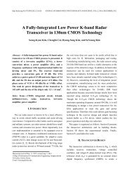
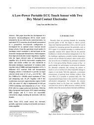
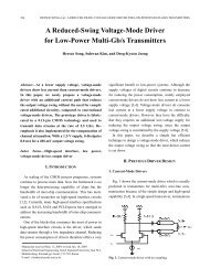
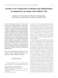
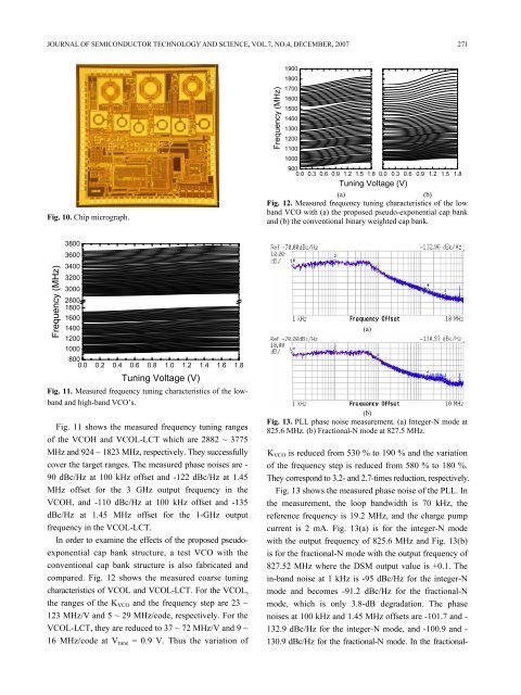
JOURNAL OF SEMICONDUCTOR TECHNOLOGY AND SCIENCE, VOL.7, NO.4, DECEMBER, 2007 271Fig. 10. Chip micrograph.<strong>Frequency</strong> (MHz)19001800170016001500140013001200110010009000.0 0.3 0.6 0.9 1.2 1.5 1.8Tuning Voltage (V)0.0 0.3 0.6 0.9 1.2 1.5 1.8(a)(b)Fig. 12. Measured frequency tuning characteristics of the lowband VCO with (a) the proposed pseudo-exponential cap bankand (b) the conventional binary weighted cap bank.<strong>Frequency</strong> (MHz)380036003400320030002800180016001400120010008000.0 0.2 0.4 0.6 0.8 1.0 1.2 1.4 1.6 1.8Tuning Voltage (V)Fig. 11. Measured frequency tuning characteristics of the lowbandand high-band VCO’s.Fig. 11 shows the measured frequency tuning rangesof the VCOH and VCOL-LCT which are 2882 ~ 3775MHz and 924 ~ 1823 MHz, respectively. They successfullycover the target ranges. The measured phase noises are -90 dBc/Hz at 100 kHz offset and -122 dBc/Hz at 1.45MHz offset <strong>for</strong> the 3 GHz output frequency in theVCOH, and -110 dBc/Hz at 100 kHz offset and -135dBc/Hz at 1.45 MHz offset <strong>for</strong> the 1-GHz outputfrequency in the VCOL-LCT.In order to examine the effects of the proposed pseudoexponentialcap bank structure, a test VCO with theconventional cap bank structure is also fabricated andcompared. Fig. 12 shows the measured coarse tuningcharacteristics of VCOL and VCOL-LCT. For the VCOL,the ranges of the K VCO and the frequency step are 23 ~123 MHz/V and 5 ~ 29 MHz/code, respectively. For theVCOL-LCT, they are reduced to 37 ~ 72 MHz/V and 9 ~16 MHz/code at V tune = 0.9 V. Thus the variation of(a)(b)Fig. 13. PLL phase noise measurement. (a) Integer-N mode at825.6 MHz. (b) <strong>Fractional</strong>-N mode at 827.5 MHz.K VCO is reduced from 530 % to 190 % and the variationof the frequency step is reduced from 580 % to 180 %.They correspond to 3.2- and 2.7-times reduction, respectively.Fig. 13 shows the measured phase noise of the PLL. Inthe measurement, the loop bandwidth is 70 kHz, thereference frequency is 19.2 MHz, and the charge pumpcurrent is 2 mA. Fig. 13(a) is <strong>for</strong> the integer-N modewith the output frequency of 825.6 MHz and Fig. 13(b)is <strong>for</strong> the fractional-N mode with the output frequency of827.52 MHz where the DSM output value is +0.1. Thein-band noise at 1 kHz is -95 dBc/Hz <strong>for</strong> the integer-Nmode and becomes -91.2 dBc/Hz <strong>for</strong> the fractional-Nmode, which is only 3.8-dB degradation. The phasenoises at 100 kHz and 1.45 MHz offsets are -101.7 and -132.9 dBc/Hz <strong>for</strong> the integer-N mode, and -100.9 and -130.9 dBc/Hz <strong>for</strong> the fractional-N mode. In the fractional-