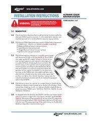
1.0 DESCRIPTION1.1 The Modbus Terminal Board is an RS-485, MODBUS RTU slave boardcapable of reading 33 channels. The first 30 channels can be any combinationof digital inputs (N/O or N/C), thermocouples (J or K), pressure inputs,4-20mA inputs, or read any sensor within the range of 0-5VDC. Channels 31<strong>and</strong> 32 can only be used for digital inputs (N/O or N/C). There is also a pickupinput. Additionally, there are 8 digital outputs which are capable of sinking60V at 500mA. Each could drive a relay, horn or other related device. Thereare also two 4-20mA outputs. All of the outputs are directly controlled bymodbus comm<strong>and</strong>s. The Modbus Terminal Board is CSA-certified for CLASS I,DIVISION 2, GROUPS C <strong>and</strong> D areas, when mounted in a suitable enclosure.The RS-485 communications is 38.4k baud, 8, N, 1. The Modbus nodenumber for each board is selected through a mechanical switch on the board.Node numbers are from 1 to 9 allowing for up to 297 analog inputs to bedaisy-chained onto one RS-485 port.This product may be used with PLC’s, HMI, or any application where inputs/outputs are needed. It can be rail mounted for easy installation.WARNING: DEVIATION FROM THESE IN-STRUCTIONS MAY LEAD TO IMPROPERENGINE/MACHINE OPERATION WHICHCOULD CAUSE PERSONAL INJURY TOOPERATORS OR OTHER NEARBY PER-SONNEL.2.0 TERMINAL BOARD2.1 A removable, dual terminal strip is used to connect the system to theequipment-mounted, discrete sensors. These sensors can be used for eithera normally-open switch, normally-closed switch, or analog inputs includingK- or J-type thermocouples. These are listed as channels 01–30. They acceptindustry-st<strong>and</strong>ard transducer signals in the range of 0-5 VDC.2.2 The Modbus Terminal Board is designed to operate with industry-st<strong>and</strong>ardvoltage – or current-amplified – output transducers in the range of 0 to 5Vdcor 0 to 25mA. Four series of transducers are available from <strong>Altronic</strong>: pressuretransducers 691201-x, 691204-x <strong>and</strong> temperature transducers 691202/203-300, 691212/213-450.2.3 PRESSURE TRANSDUCERSThe pressure transducers, <strong>Altronic</strong> P/N 691201-x <strong>and</strong> P/N 691204-x, are packagedin a rugged, sealed case with a NPT pressure port, a corrosion resistantmedia cavity, <strong>and</strong> a Packard Electric Metri-Pack connector. The ranges availableare 0-15, 0-25, 0-50, 0-100, 0-300, 0-500, 0-1000, 0-2000, <strong>and</strong> 0-5000PSIG for the 691201-x series; <strong>and</strong> 0-15, 0-20, 0-30, 0-50, 0-100, 0-300,0-500 PSIA for the 691204-x series. All have an overload rating of 1.5 times fullscale without damage. The three wires from the transducer are: +5 volt excitation,+0.5 to 4.5 volt output, <strong>and</strong> minus return. These three wires connect directly tothe back of the terminal board using cable assembly P/N 693008-x.2.4 TEMPERATURE TRANSDUCERThe temperature transducers, <strong>Altronic</strong> P/N 691202-300, 691203-300 witha temperature measurement range of +5 to 300°F <strong>and</strong> the 691212-450,691213-450 with a temperature range of -40 to +450°F are packaged ina sealed, stainless steel housing with a 5/8"-18 UNF threaded body, <strong>and</strong> aPackard Electric Metri-Pack connector. During configuration the st<strong>and</strong>ard calibrationfor the 691202/203-300 sensor is selected as dEG1 <strong>and</strong> the st<strong>and</strong>ardcalibration for the 691212/213-450 is selected by choosing dEG2. The threewires from the transducer are: +5 volt excitation, temperature output voltage,<strong>and</strong> minus return. These wires connect directly to the terminal board usingcable assembly P/N 693008-x.2.5 THERMOCOUPLE INPUTSThe terminal board can accept industry st<strong>and</strong>ard type J or K thermocouples.Automatic cold junction compensation is built-in. The units can be configuredto °F or °C. Both a high <strong>and</strong> low setpoint is associated with each channel. Themonitor can read type J thermocouples between -76°F <strong>and</strong> +1382°F (-60°C<strong>and</strong> +750°C) <strong>and</strong> type K thermocouples between -76°F <strong>and</strong> +1472°F (-60°C<strong>and</strong> +800°C).IMPORTANT: Pressure transducers willwithst<strong>and</strong> overloads as high as 1.5times rated pressure. If the overloadrating is exceeded, failure may occur.Pressure fluctuations occur in mostreciprocating systems; pick thetransducer with a rating high enoughto prevent overload by peak pressuresof pulsations. It is recommendedthat a pressure snubber be usedwhich will reduce the peak pressureapplied to the transducer. The life ofthe transducer will be extended withthe use of a snubber or pulsationdampener.IMPORTANT: Do not exceed theabsolute maximum rating of thetransducers, 350°F (176°C) for the691202/203-300 or 450°F (232°C)for the 691212/213-450. Care shouldbe taken to protect the wiring <strong>and</strong>connectors from contact with hotsurfaces.MTB IOI 4-12 All rights reserved © ALTRONIC, LLC 2012 2
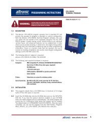
2.6 N/O <strong>and</strong> N/C INPUTSThe inputs can also accept st<strong>and</strong>ard normally-open <strong>and</strong> normally-closed contacts.Refer to figure 2 for proper wiring of these types of inputs.2.7 4-20mA inputsThe terminal board can accept 4-20mA inputs by selecting the internallyconnected200 ohm resistors, creating a termination voltage of .8 to 4.0 volts.The jumper wires between the + <strong>and</strong> – terminals for that channel must beconnected for proper operation.2.8 For each input, the corresponding CHANNEL SWITCH must be set accordingto the input type. Switches are turned ON by moving them toward the ANA-LOG OUT labeling.EACH SET SWITCH MUST BESET FOR PROPER OPERATION4321432143214321ANALOGDEG1DEG2NO/NCDIGITALINPUTJ/KTHERMO-COUPLE4-20mAINPUT2.9 Digital outputs 1 through 8 are pilot duty <strong>and</strong> turn on to common ground whenclosed. Outputs 1 through 8 are rated at 500mA, 60V.3.0 MOUNTING3.1 TERMINAL BOARDMount the Modbus Terminal Board either on the bottom or the side of themain panel. The terminal board can be rail-mounted onto commercially available32 or 35 mm DIN mounting rails. The operating temperature range of theTerminal Module is −40°F to +176°F (−40°C to +80°C).3.2 PRESSURE TRANSDUCERMount the pressure transducer in the panel or in a manifold or tube off of theengine. Do not expose the pressure transducer to temperatures above 221°F.(105°C). The second terminal module should be placed close to the first <strong>and</strong>the wire connecting them should be free of high-powered panel signals.3.3 TEMPERATURE TRANSDUCERMount the temperature transducer in a thermowell on the engine or machine.The actual sensor is located at the bottom of the transducer body; to ensureaccuracy, the tip of the probe should be surrounded by the measured media.The center of the pickup face must line up with the center of each drilled holeas the disc rotates.MTB IOI 4-12 All rights reserved © ALTRONIC, LLC 2012 3