Installation and Operating Instructions - Altronic Inc.
Installation and Operating Instructions - Altronic Inc.
Installation and Operating Instructions - Altronic Inc.
You also want an ePaper? Increase the reach of your titles
YUMPU automatically turns print PDFs into web optimized ePapers that Google loves.
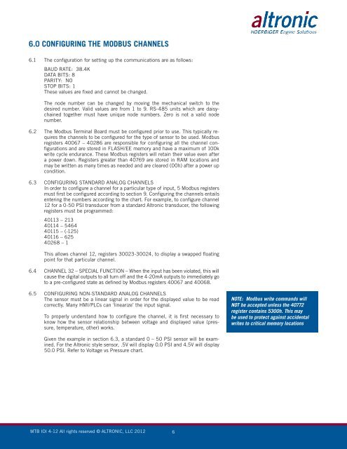
6.0 CONFIGURING THE MODBUS CHANNELS6.1 The configuration for setting up the communications are as follows:BAUD RATE: 38.4KDATA BITS: 8PARITY: NOSTOP BITS: 1These values are fixed <strong>and</strong> cannot be changed.The node number can be changed by moving the mechanical switch to thedesired number. Valid values are from 1 to 9. RS-485 units which are daisychainedtogether must have unique node numbers. Zero is not a valid nodenumber.6.2 The Modbus Terminal Board must be configured prior to use. This typically requiresthe channels to be configured for the type of sensor to be used. Modbusregisters 40067 – 40286 are responsible for configuring all the channel configurations<strong>and</strong> are stored in FLASH/EE memory <strong>and</strong> have a maximum of 100kwrite cycle endurance. These Modbus registers will retain their value even aftera power down. Registers greater than 40769 are stored in RAM locations <strong>and</strong>may be written as many times as needed <strong>and</strong> are cleared (00h) after a power upcondition.6.3 CONFIGURING STANDARD ANALOG CHANNELSIn order to configure a channel for a particular type of input, 5 Modbus registersmust first be configured according to section 9. Configuring the channels entailsentering the numbers according to the chart. For example, to configure channel12 for a 0-50 PSI transducer from a st<strong>and</strong>ard <strong>Altronic</strong> transducer, the followingregisters must be programmed:40113 – 21340114 – 546440115 – (-125)40116 – 62540268 – 1This allows channel 12, registers 30023-30024, to display a swapped floatingpoint for that particular channel.6.4 CHANNEL 32 – SPECIAL FUNCTION – When the input has been violated, this willcause the digital outputs to all turn off <strong>and</strong> the 4-20mA outputs to immediately goto a pre-configured state as defined by Modbus registers 40067 <strong>and</strong> 40068.6.5 CONFIGURING NON-STANDARD ANALOG CHANNELSThe sensor must be a linear signal in order for the displayed value to be readcorrectly. Many HMI/PLCs can ‘linearize’ the input signal.To properly underst<strong>and</strong> how to configure the channel, it is first necessary toknow how the sensor relationship between voltage <strong>and</strong> displayed value (pressure,temperature, other) works.NOTE: Modbus write comm<strong>and</strong>s willNOT be accepted unless the 40772register contains 5300h. This maybe used to protect against accidentalwrites to critical memory locationsGiven the example in section 6.3, a st<strong>and</strong>ard 0 – 50 PSI sensor will be examined.For the <strong>Altronic</strong> style sensor, .5V will display 0.0 PSI <strong>and</strong> 4.5V will display50.0 PSI. Refer to Voltage vs Pressure chart.MTB IOI 4-12 All rights reserved © ALTRONIC, LLC 2012 6


