

IST-4-027756 WINNER II D6.13.12 v1.0 Final CG “local area ...
IST-4-027756 WINNER II D6.13.12 v1.0 Final CG “local area ...
IST-4-027756 WINNER II D6.13.12 v1.0 Final CG “local area ...

You also want an ePaper? Increase the reach of your titles
YUMPU automatically turns print PDFs into web optimized ePapers that Google loves.
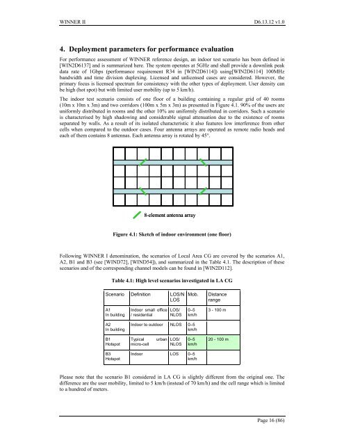
<strong>WINNER</strong> <strong>II</strong> <strong>D6.13.12</strong> <strong>v1.0</strong>4. Deployment parameters for performance evaluationFor performance assessment of <strong>WINNER</strong> reference design, an indoor test scenario has been defined in[WIN2D6137] and is summarized here. The system operates at 5GHz and shall provide a downlink peakdata rate of 1Gbps (performance requirement R34 in [WIN2D6114]) using[WIN2D6114] 100MHzbandwidth and time division duplexing. Licensed and unlicensed cases are considered. However, theprimary focus is licensed spectrum for consistency with the other types of deployment. User density canbe high (hot spot) but with limited user mobility (up to 5 km/h).The indoor test scenario consists of one floor of a building containing a regular grid of 40 rooms(10m x 10m x 3m) and two corridors (100m x 5m x 3m) as presented in Figure 4.1. 90% of the users areuniformly distributed in rooms and the other 10% are uniformly distributed in corridors. Such a scenariois characterised by high shadowing and considerable signal attenuation due to the existence of roomsseparated by walls. As a result of its isolated characteristic it also features low interference from othercells when compared to the outdoor cases. Four antenna arrays are operated as remote radio heads andeach of them contains 8 antennas. Each antenna array is rotated by 45°.8-element antenna arrayFigure 4.1: Sketch of indoor environment (one floor)Following <strong>WINNER</strong> I denomination, the scenarios of Local Area <strong>CG</strong> are covered by the scenarios A1,A2, B1 and B3 (see [WIND72], [WIND54]), and summarized in the Table 4.1. The description of thesescenarios and of the corresponding channel models can be found in [WIN2D112].Table 4.1: High level scenarios investigated in LA <strong>CG</strong>Scenario Definition LOS/NLOSMob.DistancerangeA1In buildingIndoor small office/ residentialLOS/NLOS0–5km/h3 - 100 mA2In buildingIndoor to outdoor NLOS 0–5km/hB1HotspotTypicalmicro-cellurbanLOS/NLOS0–5km/h20 - 100 mB3HotspotIndoor LOS 0–5km/hPlease note that the scenario B1 considered in LA <strong>CG</strong> is slightly different from the original one. Thedifference are the user mobility, limited to 5 km/h (instead of 70 km/h) and the cell range which is limitedto a hundred of meters.Page 16 (86)


