

IST-4-027756 WINNER II D6.13.12 v1.0 Final CG “local area ...
IST-4-027756 WINNER II D6.13.12 v1.0 Final CG “local area ...
IST-4-027756 WINNER II D6.13.12 v1.0 Final CG “local area ...

Create successful ePaper yourself
Turn your PDF publications into a flip-book with our unique Google optimized e-Paper software.
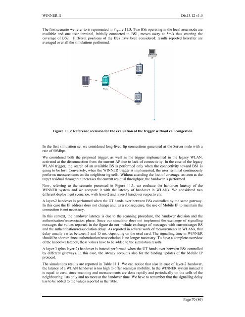
<strong>WINNER</strong> <strong>II</strong> <strong>D6.13.12</strong> <strong>v1.0</strong>The first scenario we refer to is represented in Figure 11.3. Two BSs operating in the local <strong>area</strong> mode <strong>area</strong>vailable and one user terminal, initially connected to BS1, moves away at 5m/s thus entering thecoverage of BS2. Different positions of the BSs have been considered: results reported hereafter <strong>area</strong>veraged over all the simulations performed.Figure 11.3: Reference scenario for the evaluation of the trigger without cell congestionIn the first simulation set we considered long-lived ftp connections generated at the Server node with arate of 50Mbps.We considered both the proposed trigger, as well as the trigger implemented in the legacy WLAN,activated at the disconnection from the current AP due to lack of connectivity. In the case of the legacyWLAN trigger, the search of an available BS is performed only when the connectivity toward BS1 isgoing to be lost. Conversely, when the <strong>WINNER</strong> trigger is implemented, the user terminal continuouslyperforms measurements on the neighbouring cells. Without attending the loss of coverage, as soon as thetarget residual throughput increases the current residual throughput, the handover is performed.Now, referring to the scenario presented in Figure 11.3, we evaluate the handover latency of the<strong>WINNER</strong> system and we compare it with the latency of handover in WLANs. We considered twodifferent deployment scenarios, with layer-2 and layer-3 handover respectively.A layer-2 handover is performed when the UT hands over between BSs controlled by the same gateway.In this case the IP address does not change and, as a consequence, the use of Mobile IP to maintain theconnection is not necessary.In this context, the handover latency is due to the scanning procedure, the handover decision and theauthentication/reassociation phase. Since our simulator does not implement the exchange of signallingmessages the values reported in the figure do not include exchange of messages with current/target BSand the authentication/reassociation delay. As reported in several work of measurements in WLANs, thatdelay usually varies between 5 and 15 ms, depending on the used card. The signalling time in <strong>WINNER</strong>should be shorter since authentication/reassociation is no longer necessary. To have a complete overviewof the handover latency, these values have to be added to the simulation results.A layer-3 (plus layer-2) handover is instead performed when the UT hands over between BSs controlledby different gateways. In this case, the latency accounts also for the binding updates of the Mobile IPprotocol.The simulations results are reported in Table 11.1. We can notice that also in case of layer-2 handover,the latency of a WLAN handover is too high to offer seamless mobility. In the <strong>WINNER</strong> system instead itis equal to zero, since scanning and measurements are done rapidly and periodically on the cells of theneighbouring lists only and no more at the handover time. We have to remember that the signalling delayhas to be added to the values reported in the table.Page 70 (86)


