

IST-4-027756 WINNER II D6.13.12 v1.0 Final CG “local area ...
IST-4-027756 WINNER II D6.13.12 v1.0 Final CG “local area ...
IST-4-027756 WINNER II D6.13.12 v1.0 Final CG “local area ...

You also want an ePaper? Increase the reach of your titles
YUMPU automatically turns print PDFs into web optimized ePapers that Google loves.
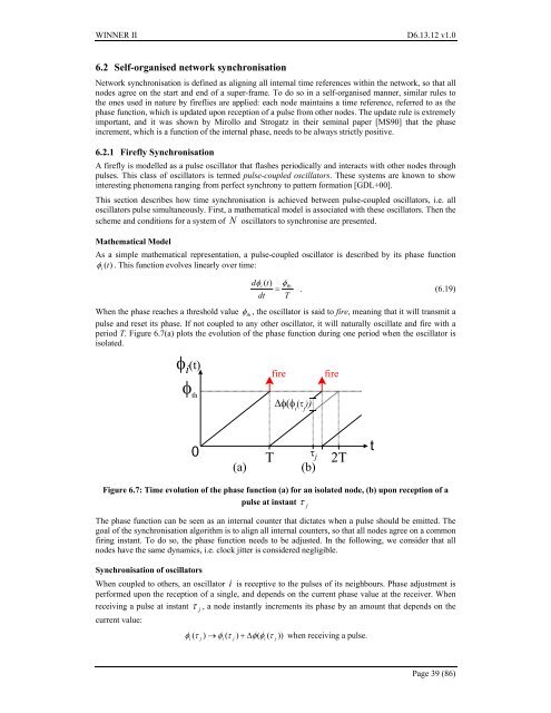
<strong>WINNER</strong> <strong>II</strong> <strong>D6.13.12</strong> <strong>v1.0</strong>6.2 Self-organised network synchronisationNetwork synchronisation is defined as aligning all internal time references within the network, so that allnodes agree on the start and end of a super-frame. To do so in a self-organised manner, similar rules tothe ones used in nature by fireflies are applied: each node maintains a time reference, referred to as thephase function, which is updated upon reception of a pulse from other nodes. The update rule is extremelyimportant, and it was shown by Mirollo and Strogatz in their seminal paper [MS90] that the phaseincrement, which is a function of the internal phase, needs to be always strictly positive.6.2.1 Firefly SynchronisationA firefly is modelled as a pulse oscillator that flashes periodically and interacts with other nodes throughpulses. This class of oscillators is termed pulse-coupled oscillators. These systems are known to showinteresting phenomena ranging from perfect synchrony to pattern formation [GDL+00].This section describes how time synchronisation is achieved between pulse-coupled oscillators, i.e. alloscillators pulse simultaneously. First, a mathematical model is associated with these oscillators. Then thescheme and conditions for a system of N oscillators to synchronise are presented.Mathematical ModelAs a simple mathematical representation, a pulse-coupled oscillator is described by its phase functionφi(t) . This function evolves linearly over time:dφi( t)φ= th. (6.19)dt TWhen the phase reaches a threshold value φth, the oscillator is said to fire, meaning that it will transmit apulse and reset its phase. If not coupled to any other oscillator, it will naturally oscillate and fire with aperiod T. Figure 6.7(a) plots the evolution of the phase function during one period when the oscillator isisolated.φ i (t)φ thfireΔφ(φ i(τ j))fire0(a)Tτ j(b)2TtFigure 6.7: Time evolution of the phase function (a) for an isolated node, (b) upon reception of apulse at instantThe phase function can be seen as an internal counter that dictates when a pulse should be emitted. Thegoal of the synchronisation algorithm is to align all internal counters, so that all nodes agree on a commonfiring instant. To do so, the phase function needs to be adjusted. In the following, we consider that allnodes have the same dynamics, i.e. clock jitter is considered negligible.Synchronisation of oscillatorsWhen coupled to others, an oscillator i is receptive to the pulses of its neighbours. Phase adjustment isperformed upon the reception of a single, and depends on the current phase value at the receiver. Whenreceiving a pulse at instant τj, a node instantly increments its phase by an amount that depends on thecurrent value:φ τ ) → φ ( τ ) + Δφ(φ ( τ )) when receiving a pulse.i(j i ji jτjPage 39 (86)


