

IST-4-027756 WINNER II D6.13.12 v1.0 Final CG “local area ...
IST-4-027756 WINNER II D6.13.12 v1.0 Final CG “local area ...
IST-4-027756 WINNER II D6.13.12 v1.0 Final CG “local area ...

You also want an ePaper? Increase the reach of your titles
YUMPU automatically turns print PDFs into web optimized ePapers that Google loves.
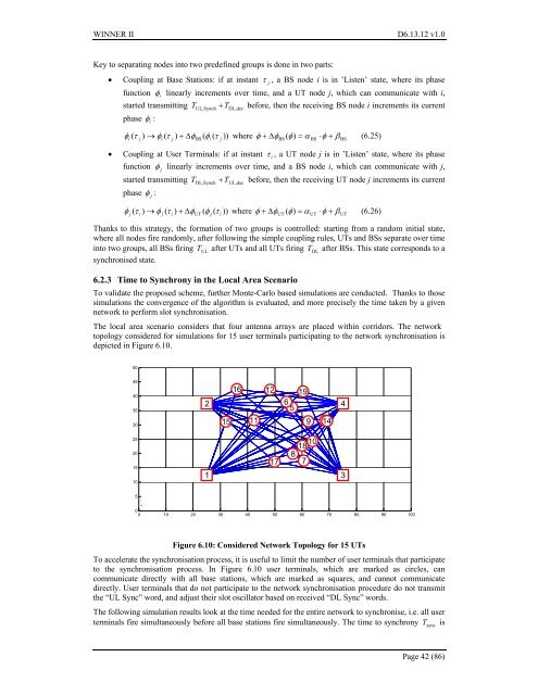
<strong>WINNER</strong> <strong>II</strong> <strong>D6.13.12</strong> <strong>v1.0</strong>Key to separating nodes into two predefined groups is done in two parts:• Coupling at Base Stations: if at instant τ j, a BS node i is in ’Listen’ state, where its phasefunction φilinearly increments over time, and a UT node j, which can communicate with i,started transmitting TUL, Synch+ TDL,decbefore, then the receiving BS node i increments its currentphase φi:φ τ ) → φ ( τ ) + Δφ( φ ( τ )) where φ + ΔφBS ( φ)= αBS⋅φ+ βBS(6.25)i(j i j BS i j• Coupling at User Terminals: if at instant τ i, a UT node j is in ’Listen’ state, where its phasefunction φjlinearly increments over time, and a BS node i, which can communicate with j,started transmitting TDL, Synch+ TUL,decbefore, then the receiving UT node j increments its currentphase φj:φ τ ) → φ ( τ ) + Δφ( φ ( τ )) where φ + ΔφUT ( φ)= αUT⋅φ+ βUT(6.26)j(i j i UT j iThanks to this strategy, the formation of two groups is controlled: starting from a random initial state,where all nodes fire randomly, after following the simple coupling rules, UTs and BSs separate over timeinto two groups, all BSs firing TULafter UTs and all UTs firing TDLafter BSs. This state corresponds to asynchronised state.6.2.3 Time to Synchrony in the Local Area ScenarioTo validate the proposed scheme, further Monte-Carlo based simulations are conducted. Thanks to thosesimulations the convergence of the algorithm is evaluated, and more precisely the time taken by a givennetwork to perform slot synchronisation.The local <strong>area</strong> scenario considers that four antenna arrays are placed within corridors. The networktopology considered for simulations for 15 user terminals participating to the network synchronisation isdepicted in Figure 6.10.50454035302151611126519913 144252015101171018873500 10 20 30 40 50 60 70 80 90 100Figure 6.10: Considered Network Topology for 15 UTsTo accelerate the synchronisation process, it is useful to limit the number of user terminals that participateto the synchronisation process. In Figure 6.10 user terminals, which are marked as circles, cancommunicate directly with all base stations, which are marked as squares, and cannot communicatedirectly. User terminals that do not participate to the network synchronisation procedure do not transmitthe “UL Sync” word, and adjust their slot oscillator based on received “DL Sync” words.The following simulation results look at the time needed for the entire network to synchronise, i.e. all userterminals fire simultaneously before all base stations fire simultaneously. The time to synchrony TsyncisPage 42 (86)


