Model ZGU... - SES Combustion AB
Model ZGU... - SES Combustion AB
Model ZGU... - SES Combustion AB

You also want an ePaper? Increase the reach of your titles
YUMPU automatically turns print PDFs into web optimized ePapers that Google loves.
2.35/UGeHeavy Duty Gas IgniterMaximum heat release: 4 kW (14,000 BTU/hr)Ionisation monitored<strong>Model</strong> <strong>ZGU</strong>...03/06man_zgu_235uge_0306_uk.docHegwein GmbH · Am Boschwerk 7 · 70469 Stuttgart · GermanyTelefon +49 (0)711 135788-0 · Fax +49 (0)711 135788-5 · E-mail: info@hegwein.de
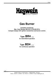
<strong>ZGU</strong>...The temperature of the ceramics must not exceed 500°C. Please see also chapter ´Technical Data;Maximum ambient temperatur´.5. Construction According to Sectional DrawingThe igniter consist essentially of the junction box (item 1), the igniter outer tube with gas inlet flange andthe inner tube with air inlet flange are fitted with 4 screws (4) with the transformer part. After loosening thescrews (4) the gas and the air flange can be detached or rotated in 90° increments according to thelocation of the supply. The gas nozzle (14) is between the gas and air pipe. The igniter´s flame ismonitored by a combined spark/ ionisation electrode (15) which are connected by extensions (13) withthe transformer part.442121481.4 1.6 1.1 Air6 5 8 5 11 12 133/8”914 154910 3 715901105°105°452145496A205025Standard model: transformer module enclosure rating IP 54 (NEMA 4), with plug connectionVersion ZTUK...Tube with endpiece20 mm longVersion ZTUS...Tube with endpiece50 mm longGas1/4”Housing material GAlView AFlange holes2 x Ø 7, hole circle diameter Ø 723 x Ø 9, hole circle diameterØ 82, distance 105°4 x Ø 8, hole circle diameterØ 80, distance 90°Igniter Sectional Drawing5
<strong>ZGU</strong>...6. Available Spare Parts and Wear and Tear PartsItem. Qty. Description Part Number Voltages Material Remarks1 1 Junction room -- Cast aluminum No spare part2 1 High voltage plug -- Bakelite No spare part3 1 Gas pressure testnipple-- Brass *Stainless steel *No spare part4 4 Allen screw -- Steel No spare part5 1 Air pressure test nipple Brass *Stainless steel *No spare part6 1 air flange,with inner tube7 1 Gas flange with outertube for<strong>ZGU</strong>...*<strong>ZGU</strong>S...*<strong>ZGU</strong>K...*8 1 Restrictor for Air inletNatural gasManufactured gasPropane/Butane9 1 Restrictor for GasNatural gasManufactured gasPropane/ButaneZ1280Z_ _ _ Tube lengthgiven shouldbe the sameas that in thepart numberfor the igniterZ1300Z...Z1310ZZ1315Z...Z142F600Z142F650Z142F650Z141F180Z141F280Z141F150Tube lengthgiven shouldbe the sameas that in thepart numberfor the igniterStainless steelStainless steelStainless steelStainless steelSteelSteelSteelSteelSteelSteelStandardCan be rotated inincrements of 90°StandardSpecialSpecialCan be rotated inincrements of 90°Bores:Ø 6.0 mmØ 6.5 mmØ 6.5 mmBores:Ø 1.8 mmØ 2.8 mmØ 1.5 mm10 2 O-Ring -- No spare part11 1 Gasket -- No spare part12 * Threaded bushing A197F1 * Depends on thenumbers ofextensions13 * extension Z169Z1Z169Z2Z169Z314 1 Gasnozzle forNatural gas andPropane/ ButaneManufactured gas15 1 Ionisation and Sparkelectrode*Overall number depending on the tube length.Please state type of igniter in your orderZ167F2Z180F2Z168Z1Stainless steelStainless steelStandardStandardSubject to wearand tear6
<strong>ZGU</strong>...12.3 Flame can be seen but no flame signal present after safety spark time haselapsedPossible Causes:Possible Reasons / Remedy.1 No ionisation signal.(Visual check with fuel valvesclosed and de-energizedigniter/ burner.).2 Igniter/ burner is wired to a Hegweinburner control:Supply voltage is releasedsimultaniously with operationvoltage..3 Igniter/ burner is wired to burnercontrol of another make:spark surpress the ionisation signal..4 Burner/Igniter has been exposed toexcessive temperature fromcombustion chamber during Burner/Igniter stand still. Ceramics are toohot, the insulation resistance hasdropped to a value that is too low..5 The setting of the fuel and airpressures at the burner/igniter arenot correct. Flame root is not in thearea of the lonisation electrode..1.1 Ionisation electrode has been burnt away.Remedy: Replace electrode and verify the correct sparkgap..1.2 Ceramic insulator is broken.Remedy: Replace insulator..2.1 Operation voltage must lag supply voltage at least by0.5 seconds..3.1 Spark voltage must be shut off 0.5 seconds before sparksafety time has elapsed..4.1 Leave blower air fully on or in cooling stage while theburner/igniter is switched off..5.1 Adjustment and correction of the corresponding devices.Use diagram values as given in the available manual..5.2 Flame is pushed out of the igniter/ burner mouth : Fuel or/and air flow insufficient..6 After failure correction of item1- 5 aflame signal is still not available.If flame signal is still not reportedthough step 1 to 5 have beenverified..6.1 Remedy: Check complete wiring with test diode A10Z2.See manual.12.4 Shut off during operationPossible Causes:.1 Varying back pressures or supplypressures cause the flame to trip.Possible Reasons / remedy.1.1 Check pressure at the test nipples. Fluctuations require adifferential pressure regulator on the air and fuel supplyside..1.2 Burner or igniter test should be carried out outsidecombusstion chamber.Local safety regulations must be observed..2 Pilot flame is strongly influenced orwhen suffocated by the main flame..2.1 Remedy: Change igniter position.2.2 Remedy: A more powerful burner/ igniter may berequested.10
<strong>ZGU</strong>...13. Approvals12
<strong>ZGU</strong>...13