Operating and mounting manual Safety shut off valve solenoid valve ...
Operating and mounting manual Safety shut off valve solenoid valve ...
Operating and mounting manual Safety shut off valve solenoid valve ...

You also want an ePaper? Increase the reach of your titles
YUMPU automatically turns print PDFs into web optimized ePapers that Google loves.
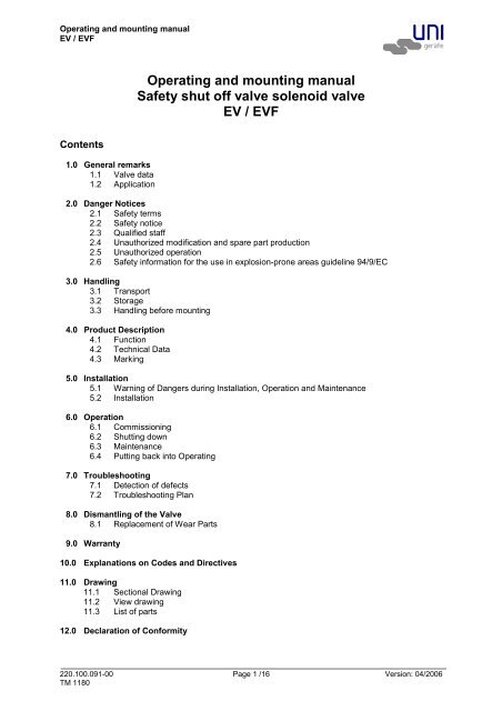
<strong>Operating</strong> <strong>and</strong> <strong>mounting</strong> <strong>manual</strong>EV / EVF<strong>Operating</strong> <strong>and</strong> <strong>mounting</strong> <strong>manual</strong><strong>Safety</strong> <strong>shut</strong> <strong>off</strong> <strong>valve</strong> <strong>solenoid</strong> <strong>valve</strong>EV / EVFContents1.0 General remarks1.1 Valve data1.2 Application2.0 Danger Notices2.1 <strong>Safety</strong> terms2.2 <strong>Safety</strong> notice2.3 Qualified staff2.4 Unauthorized modification <strong>and</strong> spare part production2.5 Unauthorized operation2.6 <strong>Safety</strong> information for the use in explosion-prone areas guideline 94/9/EC3.0 H<strong>and</strong>ling3.1 Transport3.2 Storage3.3 H<strong>and</strong>ling before <strong>mounting</strong>4.0 Product Description4.1 Function4.2 Technical Data4.3 Marking5.0 Installation5.1 Warning of Dangers during Installation, Operation <strong>and</strong> Maintenance5.2 Installation6.0 Operation6.1 Commissioning6.2 Shutting down6.3 Maintenance6.4 Putting back into <strong>Operating</strong>7.0 Troubleshooting7.1 Detection of defects7.2 Troubleshooting Plan8.0 Dismantling of the Valve8.1 Replacement of Wear Parts9.0 Warranty10.0 Explanations on Codes <strong>and</strong> Directives11.0 Drawing11.1 Sectional Drawing11.2 View drawing11.3 List of parts12.0 Declaration of Conformity_______________________________________________________________________________________________________220.100.091-00 Page 1 /16 Version: 04/2006TM 1180
<strong>Operating</strong> <strong>and</strong> <strong>mounting</strong> <strong>manual</strong>EV / EVF1.0 General remarksThis operating <strong>manual</strong> includes instructions to assemble <strong>and</strong> operate the <strong>valve</strong> in the prescribed <strong>and</strong>safe way. Additionally, the adeqaute operating instructions (BTA) of each special <strong>solenoid</strong> drivemust be considered.Series MG... 220.000.038Series MG...X 220.000.040Series MG…Xme 220.000.039If any difficulties appear that can not be solved by means of the operation instructions, furtherinformation may be dem<strong>and</strong>ed from the manufacturer.This operating <strong>manual</strong> is in accordance with the relevant valid EN safety st<strong>and</strong>ards <strong>and</strong> the validprescriptions <strong>and</strong> rules of the Federal Republic of Germany.If the <strong>solenoid</strong>s are used abroad of the FRG, the operator <strong>and</strong>/or the person who is responsible for theplant concept must take care that the valid national rules are met.The manufacturer reserves the right of any technical change <strong>and</strong> improvement.The use of these operating instructions suppose the qualification of the user according to paragraph2.3 “qualified staff”.The operating staff must be trained in accordance with the operating instructions. The operating<strong>manual</strong> must always be available at the location where used.1.1 Valve InstructionManufacturer:UNI Geräte E. MangelmannElektrotechnische Fabrik GmbHHoltumsweg 13D-47652 WeezeTelefon: +49 (0) 2837/9134-0Fax: +49 (0) 2837/1444E-Mail: info@uni-geraete.deHomepage: www.uni-geraete.deDesignationDirectly functioning, currentless closed, spring safety <strong>shut</strong> <strong>off</strong> <strong>valve</strong> with magnet drive.Type test acc. to DIN EN 264Working pressure: 5 EV(F) 5bar10 EV(F) 10bar25 EV(F) 25bar40 EV(F) 40barAmbient temperature: -10°C to + 60°°C (263K to 333K)Medium temperature: EV -10°C bis + 140°C (263K bis 413K)EVF -10°C bis + 200°C (263K bis 473K)Fitting position:Switching cycles:vertical drive ± 5°, with order supplement „W“ vertical orhorizontal.1000 cycles/h for <strong>solenoid</strong> drives with one winding,20 cycles/h for <strong>solenoid</strong> drives with pickup <strong>and</strong> holdingwinding MG…A 1 / A 2 / A 3 see section 4.2.600 cycles/h for MG…A5_______________________________________________________________________________________________________220.100.091-00 Page 2 /16 Version: 04/2006TM 1180
<strong>Operating</strong> <strong>and</strong> <strong>mounting</strong> <strong>manual</strong>EV / EVFFlange connection measures acc. to DIN EN 1092-2 / ANSIFlange DNFlange ANSIPN TÜV-Reportno.151/2"203/4"253/4"DesignpressurePS = PN5 EV..NÜ..92/93 25 S7/99 X X X PN 1610 EV..NÜ..92/93 40 S7/99 X X X PN 2525 EV..NÜ..92/93* 40 S7/99 X X X PN 4040 EV..NÜ..92/93 40 S7/99 X X X PN 40X Type test acc., O Acceptance test certificate 3.2 possible, - not available,* For liquefied gas in its liquid form according to DIN 32725Flange connection measures acc. to DIN EN 1092-2 / ANSIFlange DNFlange ANSIPN TÜV-Reportno.151/2"203/4"253/4"DesignpressurePS = PN5 EVF..NÜ..92/93 25 S8/99 X X X PN 1610 EVF..NÜ..92/93 40 S8/99 X X X PN 2525 EVF..NÜ..92/93 40 S8/99 X X X PN 4040 EVF..NÜ..92/93 40 S8/99 X X X PN 40X Type test acc., O Acceptance test certificate 3.2 possible, - not available,Voltage: 24V– 420V (–15% bis +10%)Protection type:IP54 or IP65Frequency:40 – 60 HzPower:10 – 4000WDetails to the electrical data can be found on the type sign<strong>and</strong> the adeqaute operating instructions ofthe <strong>solenoid</strong> <strong>valve</strong>s.1.2 ApplicationThe UNI Geräte <strong>solenoid</strong> <strong>valve</strong> EV <strong>and</strong> EVF are used as automatic safety <strong>shut</strong>-<strong>off</strong> <strong>valve</strong>s to secure, tolimit, <strong>shut</strong>-<strong>off</strong> <strong>and</strong> release Liquid gas heating installation <strong>and</strong> in steam boiler plant.Qualified for fuel oil EL, M <strong>and</strong> S according to DIN 51603 <strong>and</strong> liquid gas to DIN 61522 in liquid state<strong>and</strong> other liquids having a viscosity rate up to 75mm²/s.If used in other cases, the operator must carefully check if construction/design of <strong>valve</strong>, accessories<strong>and</strong> materials are suitable for the new application. The range of application is subject to theresponsibility of the plant planner. The service life of the <strong>valve</strong> is 20 years.2.0 Danger Notices2.1 <strong>Safety</strong> TermsThe signal terms DANGER, CAUTION und NOTICE are used in this operating <strong>manual</strong> in case ofnotices concerning special dangers, or for unusal information requiring a special marking.DANGER! means that in case of non-observance there is danger to life <strong>and</strong>/orconsiderable damage.CAUTION! means that in case of non-observance there is danger of injury <strong>and</strong>/ordamage.NOTICE! means that attention is drawn to technical correlations/connections._______________________________________________________________________________________________________220.100.091-00 Page 3 /16 Version: 04/2006TM 1180
<strong>Operating</strong> <strong>and</strong> <strong>mounting</strong> <strong>manual</strong>EV / EVFObservance of other, not especially marked notices concerning transport, assembly, operation <strong>and</strong>maintenance <strong>and</strong> other data (in the operating <strong>manual</strong>, product documentation <strong>and</strong> at the unit itself) isalso essential, in order to avoid disturbances that might affect direct or indirect damage to property orinjury to persons.2.2 <strong>Safety</strong> NoticeNon observance of safety instructions can lead to loss of any claim for damages.Non observance can lead to the following mentioned dangers:• Failure of important functions of the <strong>valve</strong>/plant• Endangering of persons by electrical or mechanical influences.• Protection against accidental contact for moving parts may not be removed as long as the<strong>valve</strong> is in operation.• Leakage of dangerous media (e.g. explosive, toxic, hot) must be removed in the way thatthere is no danger for persons or environment. Laws <strong>and</strong> regulations must be observed.2.3 Qualified PersonnelThese are persons who are familiar with erection, assembly, starting, operation <strong>and</strong> maintenance ofthe product <strong>and</strong> who have special qualifications acc. to their activities <strong>and</strong> functions, e.g.:• Instruction <strong>and</strong> obligation to carry out <strong>and</strong> meet all regional <strong>and</strong> in-house orders <strong>and</strong>requirements.• Education or instruction according to the safety engineering st<strong>and</strong>ards in use <strong>and</strong>maintenance of adequate safety <strong>and</strong> working protection equipment.• Training in first aid.2.4 Unauthorized Modification <strong>and</strong> Spare Part ProductionModification or changes of the <strong>valve</strong> are only allowed after agreement of the manufacturer. Originaldrawings <strong>and</strong> accessories authorized by the manufacturer are for safety purposes. The use of otherparts or unauthorized constructive changes at the <strong>valve</strong> by third persons may cancel <strong>and</strong> abolish themanufacturere’s liability for resulting consequences.2.5 Unauthorized OperationOperational reliability of the delivered <strong>valve</strong> is only guaranteed in case of determined use inaccordance to paragraph 1 of the operating <strong>manual</strong>. The application limits mentioned on the typesign may on no account be exceeded.2.6 <strong>Safety</strong> information for the use in explosion-prone areas guideline 94/9/EC• The temperature of the medium must not exceed the respective temperature class, <strong>and</strong>respectively, the respective maximum permitted medium temperature as per operationguideline.• If the <strong>valve</strong> is heated (e.g. heating jacket), care must be taken, that the specified temperatureclass is kept in the time.• The <strong>valve</strong> must be connected to the ground.In the case most simple this can be realized via pipe screws by means of tooth disc.Otherwise the connection to the ground must be implemented by other measures e.g. cablelinks.• Control <strong>valve</strong>s, electrical <strong>and</strong> electrical/mechanical drives as well as sensors must undergo aseparate conformity check as per ATEX. In doing so the respective safety <strong>and</strong> explosionprotection information in the operation instructions are to taken into special consideration.Furthermore we point out the guideline 95/C332/06(ATEX 118a), which include the minimumregulations for the improvement of the health-related situation <strong>and</strong> the safety of the employees, whomight be jeopardized by an explosive atmosphere.3.0 H<strong>and</strong>ling3.1 TransportFor any transport works, the generally recognised technical rules <strong>and</strong> st<strong>and</strong>ards as well as rules forprevention of accidents must be observed._______________________________________________________________________________________________________220.100.091-00 Page 4 /16 Version: 04/2006TM 1180
<strong>Operating</strong> <strong>and</strong> <strong>mounting</strong> <strong>manual</strong>EV / EVFIn case of transport, storage <strong>and</strong> stopping, the flange protection caps must be mounted at both <strong>valve</strong>flanges.The goods to be transported must be carefully treated. During transport, the <strong>valve</strong> must be protectedagainst strokes, impacts or vibration. The coat of lacquer may not be damaged. Transport temperatureis –20°C up to +60°C.Never transport the <strong>valve</strong> at screwed cable gl<strong>and</strong>s, appliance plugs or add-on units. The <strong>valve</strong>can be transported at ring nuts, flange borings or by means of a belt under the <strong>solenoid</strong> drive.Transport the <strong>valve</strong> in a case or on a pallet with smooth base <strong>and</strong> put it softly on plain floor. Never putthe <strong>valve</strong> on limit switch box.The goods must be checked on completeness <strong>and</strong> transport damage. See also section 9.03.2 StorageIf the <strong>valve</strong> is not installed immediately after delivery, it must be stored properly.• Storage temperature -20°C up to +60°C, dry <strong>and</strong> clean.• The lacquering protects against corrosion in neutral dry atmosphere. Do not damage colour.• In humid rooms, a drying agent or a heating resp. is necessary because of condensation ofwater.Requirements according to DIN 7716 (products made of caoutchouc <strong>and</strong> rubber) must be met.3.3 H<strong>and</strong>ling before Assembly• In case of <strong>valve</strong> with protection caps, they must be removed before being mounted!• Protect against atmospheric influences such as humidity (otherwise use drying agent).• Appropriate treatment protects against damage.4.0 Product descriptionThe UNI-Geräte <strong>solenoid</strong> <strong>valve</strong>s of the series EV <strong>and</strong> EVF are directly controlled currentless closed<strong>shut</strong>-<strong>off</strong> <strong>valve</strong>s with fast <strong>shut</strong>-<strong>off</strong> function as per DIN EN 264 (liquid gas in liquid gas phase as per DIN51622) with <strong>solenoid</strong> <strong>valve</strong>.Sectional drawing 11.1 Fig. in Fig. 1 <strong>and</strong> 2 shows the <strong>valve</strong> construction.4.1 FunctionOn switching on of the <strong>solenoid</strong> drive (800) the <strong>solenoid</strong> core (207) is pulled against the upper part ofhousing (106). The pressure spring (503) is further prestressed <strong>and</strong> the <strong>valve</strong> disk (200) opens the<strong>valve</strong> cross section. The <strong>valve</strong> is open.On <strong>shut</strong>ting <strong>off</strong>, supply interruption or supply failure the <strong>valve</strong> closes to the <strong>solenoid</strong> drive. The <strong>valve</strong>disk (200) closes due to the pre-stress of the pressure spring (503). The <strong>valve</strong> is closed.4.2 Technical DataOpening times:Closing times:0,3 – 0,7s , depends upon nominal width< 1sSolenoid –drive types MG...Flange DN15 20 25Flange ANSI1/2" 3/4" 1"5 EV...NÜ..92/93 014 014 01610 EV...NÜ..92/93 016 016 01925 EV...NÜA..92/93 016A1 016A1 018A225 EV…NÜA..92/93* 018A1 018A1 019A140 EV...NÜA..92/93 019A1 019A1 019A2* For liquefied gas in its liquid_______________________________________________________________________________________________________220.100.091-00 Page 5 /16 Version: 04/2006TM 1180
<strong>Operating</strong> <strong>and</strong> <strong>mounting</strong> <strong>manual</strong>EV / EVFFlange DNFlange ANSI151/2"203/4"251"5 EVF...NÜ..92/93 014 014 01610 EVF...NÜ..92/93 016 016 01925 EVF...NÜA..92/93 016A1 016A1 018A240 EVF...NÜA..92/93 019A1 019A1 019A2Drive types with “A” consist of pickup <strong>and</strong> holding windingMax. <strong>valve</strong> loading by pipe powerThe indicated moments may not work longer than 10s.DN 8 10 15 20 25 32 40 50 65 80 100 125 150Torsion Nm 80 35 50 86 125 160 200 250 1) 325 1) 400 1) - - -Bending Nm 35 70 105 225 340 475 610 1100 1600 2400 5000 6000 76001) Not valid in case of <strong>valve</strong>s with flangesStarting torque, pipe screws greasedDN 8 10 15 20 25 32 40 50 65 80 100 125 150Torque Nm 20 30 30 30 30 50 50 50 50 50 80 160 160Starting torque, product screws <strong>and</strong> nuts greasedScrew M6 M8 M10 M12 M16 M20 M24Torque Nm 5 11 22 39 70 110 1504.3 MarkingThe type sign on the <strong>solenoid</strong> drive has the following information:• Fabricator• Valve type, nominal width, pressure <strong>and</strong> temperature indication, fitting position• Year of construction/ production no.• TÜV-report-no:• Valve class <strong>and</strong> <strong>valve</strong> group acc. to DIN EN 264• CE-sign <strong>and</strong> no. of relevant location to 97/23/EC• Fluid group <strong>and</strong> test pressure PT to 97/23/EC• Solenoid drive type• Electr. performance• Voltage• Frequency• Protection typeWhen using <strong>solenoid</strong> drives for x-protection zone 1 refer to information in the valid operatinginstructions.Refer also to section 10.0.5.0 Installation5.1 Warning of Dangers during Installation, Operation <strong>and</strong> MaintenanceDANGER!Safe operation of the <strong>valve</strong> can only be guaranteed if it is installed, commissioned<strong>and</strong> maintained by qualified personnel (see point 2.3 “Qualified staff“) correctly <strong>and</strong>in observance of the warnings in this operating <strong>manual</strong>. Apart from that, theoperation safety order <strong>and</strong> the qualified use of tools <strong>and</strong> protection equipment mustbe guaranteed. The operating instructions for the <strong>valve</strong> must be observed during allwork on or with the <strong>valve</strong>. Failure to observe these instructions may result in injuryor in damage to the <strong>valve</strong> or other installations._______________________________________________________________________________________________________220.100.091-00 Page 6 /16 Version: 04/2006TM 1180
<strong>Operating</strong> <strong>and</strong> <strong>mounting</strong> <strong>manual</strong>EV / EVFWhen the <strong>valve</strong> is used as a final sealing element, a safety precaution e.g. blanking disc, blind flange,etc., in accordance with the code of practice of the German Technical <strong>and</strong> Scientific Association forGas <strong>and</strong> Water (DVGW) is recommended during all repair work.5.2 InstallationApart from the general installation guidelines, the following points should be observed:NOTICE!• Remove the flange covers.• The inside of the <strong>valve</strong> <strong>and</strong> the pipeline must be free from foreign particles.• Observe the installation position in relation to the flow direction, see markingson the <strong>valve</strong>.• Centre gaskets between the flanges.• The connecting flanges must be aligned.• Ensure that none of the components is strained during installation.• The <strong>valve</strong> must not be used as a fixed point; it is supported by the pipeworksystem.• Protect <strong>valve</strong>s from soiling, particularly during construction work.• Thermal expansion of the pipework must be equalized using compensators.The <strong>valve</strong> can be installed with upright but not suspended <strong>solenoid</strong> drive. Valves with order suffix “W”in the type designation can be installed with horizontal <strong>solenoid</strong> drive.NOTICE!Please observe the <strong>solenoid</strong> drive operating instructions (BTA).6.0 OperationDANGER!Before commissioning a new installation or before starting up an installation againafter repairs or modifications, ensure:• The proper completion of all installation <strong>and</strong> assembly work!• Commissioning only by “qualified staff” (see point 2.3).• Installation or repair of existing guards <strong>and</strong> protection equipment.6.1 Commissioning• Before commissioning, check the data on material, pressure, temperature <strong>and</strong> flow directionwith the layout plan of the pipework system.• Depending on the field of application, the local regulations have to be observed, e.g. theoperation safety order.• Residues in the pipework <strong>and</strong> the <strong>valve</strong> (dirt, weld beads, etc.) will inevitably result in leaks.• Leakage inspection of the installed <strong>valve</strong>.6.2 Shutting Down• Depending on the field of application, the local regulations have to be observed, e.g. theoperation safety order.6.3 MaintenanceSolenoid <strong>valve</strong>s have to be checked at regular intervals for proper function <strong>and</strong> internal leak tightness.The intervals for regular inspections have to be defined by the operator according to the operatingconditions. UNI-Geräte recommends an internal visual inspection once a year <strong>and</strong> an overhaul of the<strong>valve</strong> after 2 years or after the following number of switching cycles at the latest:Application DN ≤ 25 ≤ DN 80 ≤ DN 150 > DN 150temperature≤ 25°C 150 000 75 000 25 000 20 000> 25°C 50 000 25 000 25 000 5 000_______________________________________________________________________________________________________220.100.091-00 Page 7 /16 Version: 04/2006TM 1180
<strong>Operating</strong> <strong>and</strong> <strong>mounting</strong> <strong>manual</strong>EV / EVF6.4 Putting Back into OperationWhen putting a <strong>valve</strong> back into operation, ensure that all the necessary steps described in section 5.2(Installation) <strong>and</strong> section 6.1 (Commissioning) are repeated.7.0 Troubleshooting7.1 Detection of defectsDANGER!Be sure to observe the safety instructions during troubleshooting.If the malfunctions cannot be remedied using the following “Troubleshooting plan (7.2)” pleasecontact the manufacturer.In the event of faults in the function or operating behaviour of the <strong>valve</strong>, check whether the installationwork was carried out <strong>and</strong> completed as described in this operating <strong>manual</strong>.Depending on the field of application, the operation safety order must be observed.Check the data on material, pressure, temperature, voltage <strong>and</strong> flow direction with the layout plan ofthe pipework system. In addition, check whether the operating conditions correspond to the technicaldata in the data sheet or on the rating plate.7.2 Troubleshooting PlanMalfunction Possible causes RemedyNo flowValve does not openSwitch on <strong>solenoid</strong> drive (800)Check operating voltageWorking pressure too highCompare working pressure with the dataon the rating plateFlange covers were not removed Remove flange coversLow flow rate Clogging in the pipework system Check pipework systemValve leaking at seat, Valve seat gasket (400) or <strong>valve</strong> seat See section 8 or replace <strong>valve</strong>no internal tightness (100) damaged by external particlesNo external tightness Gaskets damaged See section 8 or replace <strong>valve</strong>Valve does not close Connected voltage too high Check whether there is residual voltage,see section 4.1Flange fracture (<strong>valve</strong>/ Screws not tightened uniformly, mating Align pipework.pipework)flanges not alignedInstall new <strong>valve</strong>NOTICE!Observe section 10.0 before all installation <strong>and</strong> repair work!Observe section 6.4 when putting the <strong>valve</strong> back into operation!8.0 Dismantling of the ValveIn addition to the general installation guidelines <strong>and</strong> the operation safety order, the following pointsmust also be observed:DANGER!• Depressurised pipework system• Cooled medium• Emptied installation_______________________________________________________________________________________________________220.100.091-00 Page 8 /16 Version: 04/2006TM 1180
<strong>Operating</strong> <strong>and</strong> <strong>mounting</strong> <strong>manual</strong>EV / EVF• Vent pipework systems containing corrosive, inflammable, aggressive or toxicmedia• Have dismantling work carried out only by qualified staff (see point 2.3)8.1 Replacement of Wear PartsShut down the <strong>valve</strong> as described in section 6.2.Switch <strong>off</strong> <strong>and</strong> dismantle the <strong>solenoid</strong> drive as described in the operating <strong>manual</strong> of the <strong>solenoid</strong> drive.DANGER!After continuous operation, the <strong>solenoid</strong> drive may be hot! Danger of burns!Loosen the setscrew (941). Loosen the upper part of housing (106) by turning tothe right <strong>and</strong> screwing it <strong>off</strong>.NOTICE!The complete upper part of housing (106) is under spring power.Remove spring bolt (210) with pressure spring (503) from the <strong>solenoid</strong> core (207).Release safety bolt (902/2) <strong>and</strong> remove it from the <strong>valve</strong> pin (214). Put the <strong>solenoid</strong>core (207) complete with <strong>valve</strong> pin (214) <strong>and</strong> dust guard membrane (407) onto aclear surface.Loosen cylinder screw (910/2) <strong>and</strong> pull <strong>off</strong> the limit switch actuator (513) from the<strong>valve</strong> spindle (205) <strong>and</strong> remove it.Loosen hex. nut (901/3) <strong>and</strong> remove it with limit switch consoles (512); removelimit switches (803) as well.NOTICE!Before doing so disconnect limit switch pos. 803.EV (lip ring sealing)Loosen cylinder screws (910/1) <strong>and</strong> remove them with the lock washers (905/1).Remove spacer (110).Lift the complete parts (115; 200/1; 201; 205; 212; 249; 902/1; 912 und 950) out ofthe <strong>valve</strong> housing (100). Pull of the guiding parts (115; 212; 249) from the <strong>valve</strong>spindle (205).Remove split-pin (912) <strong>and</strong> pull out safety bolt (902/1).NOTICE!The ball (950) falls out.Remove the complete <strong>valve</strong> disk (200/1).EVF (sealing of expansion bellows)Drive spring dowel sleeve (943) out of torsion protection (227).Loosen cylinder screws (910/1) <strong>and</strong> remove them with the lock washers (905/1).Lift <strong>off</strong> spacer (110).Lift the complete parts (200/1; 201; 205; 227; 504, 507, 902/1, 912 und 950) out ofthe <strong>valve</strong> housing (100). Pull the torsion protection (227) <strong>off</strong> the <strong>valve</strong> spindle(205).Remove split-pin (912) <strong>and</strong> pull out the safety bolt (902/1)n._______________________________________________________________________________________________________220.100.091-00 Page 9 /16 Version: 04/2006TM 1180
<strong>Operating</strong> <strong>and</strong> <strong>mounting</strong> <strong>manual</strong>EV / EVFNOTICE!The ball falls out (950).Lift <strong>off</strong> the complete <strong>valve</strong> disk (200/1 respectively 200/2).All parts marked as wear <strong>and</strong> tear parts are to be replaced. In case of damages atthe <strong>valve</strong> disk sealing (400) the <strong>valve</strong> disk (200/1) is to be replaced completely. Incase of damages <strong>and</strong> drag lines at the <strong>valve</strong> disk (200/2) the latter is to bereplaced completely. In case of cracks <strong>and</strong> pressure marks at the expansionbellows (504) the latter is to be completely removed including the expansionbellows piece (507).NOTICE!Before installation O-rings (403/X), gaskets (402/X), lip rings (404/X) <strong>and</strong> in case ofsealing metal against metal the packing (406) are to be replaced.Assemble the <strong>valve</strong> in the reverse order to the dismantling.CAUTION!Install wear parts carefully <strong>and</strong> properly <strong>and</strong> do not damage them during assembly.Examine the <strong>valve</strong> for internal <strong>and</strong> external leaks <strong>and</strong> finally carry out a function test.9.0 WarrantyScope <strong>and</strong> period of the warranty is specified in the edition of the “General Terms of Business of theUNI-Geräte E. Mangelmann Elektrotechnische Fabrik GmbH” valid at the time of delivery or else in thepurchase agreement.We warranty that the <strong>valve</strong> is free from faults in line with the state of the art <strong>and</strong> for the confirmed fieldof application.No warranty claims will be accepted for damage resulting from improper use or failure to observethese operating <strong>and</strong> installation instructions, the statutory accident prevention regulations, the EN, DIN<strong>and</strong> VDE st<strong>and</strong>ards <strong>and</strong> other codes <strong>and</strong> regulations.Warranty claims will also not be accepted for damage occurring during operation due to operatingconditions deviating from those specified in the data sheet or in other agreements.Justified complaints will be remedied by reworking by us or specialist companies authorised by us.Claims going beyond the scope of the warranty will not be accepted. The customer shall have no rightto the supply of a replacement <strong>valve</strong>.Maintenance work, installation of parts from other manufacturers, any modifications to the design <strong>and</strong>natural wear are not covered by the warranty.Transport damage must be reported not to us but without delay to your responsible goods h<strong>and</strong>lingcompany, the railway company or the shipping agent as otherwise all claims for damages againstthese companies will be voided._______________________________________________________________________________________________________220.100.091-00 Page 10 /16 Version: 04/2006TM 1180
<strong>Operating</strong> <strong>and</strong> <strong>mounting</strong> <strong>manual</strong>EV / EVF10.0 Explanations on Codes <strong>and</strong> DirectivesThe Commission of the European Union has laid down common directives for the free trading ofgoods within the Union specifying minimum requirements for safety <strong>and</strong> health protection. The CEsymbol confirms that products comply with the EU directives, i.e. in conformity with the relevant, inparticular harmonised st<strong>and</strong>ards. Directives 90/396/EEC, 98/37/EC <strong>and</strong> 97/23/EC are of relevance forthe gas <strong>solenoid</strong> <strong>valve</strong> (mechanical part).Notes on Directive 90/396/EEC (Appliances Burning Gaseous Fuels):The <strong>valve</strong>s have been developed, manufactured <strong>and</strong> tested in accordance with harmonised st<strong>and</strong>ardDIN EN 161 (DIN 3394-1, DIN 3391) <strong>and</strong> comply with the relevant requirements of the Union Directive90/396/EEC. Unless otherwise stated separately, this has been confirmed by a type test.Notes on Directive 98/37/EC (Machinery Directive):The <strong>valve</strong>s have been developed, manufactured <strong>and</strong> tested in accordance with Directive 98/37/EC.Notes on Directive 97/23/EG (Pressure Equipment Directive, DGRL):It has been conformed that the quality assurance in design control, manufacture <strong>and</strong> final acceptanceof the manufacturer, UNI-Geräte E. Mangelmann Elektrotechnische Fabrik GmbH, satisfy the requirementsof 98/23/EC Annex III Module H. The gas <strong>solenoid</strong> <strong>valve</strong>s comply with the fundamental requirementsof Directive 97/23/EC. Valves with permissible working pressures ≤ 0.5 bar, DN ≤ 25 <strong>and</strong> allproducts certified in accordance with category I <strong>and</strong> with 94/396/EEC are not covered by 97/23/EC.Only products covered by DGRL <strong>and</strong> classified in category I or higher may be marked in accordancewith 97/23/EC. Fluid group 1 includes explosive, inflammable <strong>and</strong> toxic media. Fluid group 2 includesmedia not belonging to fluid group 1.Directives 73/23/EEC <strong>and</strong> 89/336/EEC are of relevance for the <strong>solenoid</strong> drive (800).Notes on Directive 73/23/EC (Low Voltage Directive):The drives have been developed, designed <strong>and</strong> manufactured in accordance with st<strong>and</strong>ard “ElectromagneticDevices” DIN EDV 0580. The requirements of the Low Voltage Directive that is applicablefor rated voltages from 50 to 1000 V AC <strong>and</strong> 75 to 1500 V DC are therefore also satisfied.Note on Directive 89/336/EEC (EMC Directive):The magnet fulfil the requirements of the product family st<strong>and</strong>ards EN 55014-1,-2 , EN 61000-3-2, -3-3for the industrial sector as well as for the sectors of housing, business <strong>and</strong> trade in small businesses.When using AC <strong>and</strong> DC versions, the user must provide a suitable mains filter (e.g. X capacitor 47 nF)at the connection to the mains power supply in order to suppress the physical mains-borne turn-<strong>off</strong>interference of the <strong>solenoid</strong> coil.Solenoid drives as drive elements for <strong>valve</strong>s do not represent independently operated devices in thesense of the EMC Directive <strong>and</strong> are only further processed by specialist companies or are installed ina machine. Commissioning is not permitted until it has been determined that the whole machine orplant complies with the provisions of the EMC Directive.For <strong>solenoid</strong> drives for explosion-proof zone 1, see the relevant operating <strong>manual</strong> for the <strong>solenoid</strong>drives.Note concerning ex-guideline 94/9/EC (explosion guideline ATEX):The product is not subject to guideline 94/9/EC, since due to the loads occurring during practicaloperation, there is no effective source of ignition even in case of an error case to be assumed. Thisalso applies for spring-loaded components, like for example the pneumatic drive. In case of electricdrives, sensors or other electric components the application as per 94/9/EC is to be checkedseparately._______________________________________________________________________________________________________220.100.091-00 Page 11 /16 Version: 04/2006TM 1180
<strong>Operating</strong> <strong>and</strong> <strong>mounting</strong> <strong>manual</strong>EV / EVF11.0 Drawing11.1 Fig.1 EV sectional drawingO = Wearing parts_______________________________________________________________________________________________________220.100.091-00 Page 12 /16 Version: 04/2006TM 1180
<strong>Operating</strong> <strong>and</strong> <strong>mounting</strong> <strong>manual</strong>EV / EVF11.1 Fig.2 EVF sectional drawingO = Wearing parts_______________________________________________________________________________________________________220.100.091-00 Page 13 /16 Version: 04/2006TM 1180
<strong>Operating</strong> <strong>and</strong> <strong>mounting</strong> <strong>manual</strong>EV / EVF11.2 View drawing11.3 List of partsPos./ Item Stück/ Qty. Benennung Description100 1 Ventilgehäuse Valve chamber106 1 Gehäuseoberteil Upper part of housing110 1 Distanzstück Spacer115 1 Dichtplatte Sealing board200/1 1 Ventilteller Valve disk200/2 1 Ventilteller Valve disk201 1 Tellerscheibe Disc plate205 1 Ventilspindel Valve spindle207 1 Magnetkern Solenoid core209 1 Abwurfbolzen Discharge bolt210 1 Federbolzen Spring bolt212 1 Spindelführung Spindle guide214 1 Ventilstift Valve pin227 1 Verdrehschutz Torsion protection249 1 Endschalter Konsolenhalter Limit switch console owner400 1 Ventiltellerdichtung Valve disc sealing402/1 1 Flachdichtung Gasket402/2 1 Flachdichtung Gasket402/3 1 Flachdichtung Gasket403/1 1 O-Ring O-ring403/2 1 O-Ring O-ring404/1 2 Lippenring Lip-ring404/2 1 Lippenring Lip-ring405 1 Abstreifring Scraper ring406 2 Packung Packing407 1 Staubschutzmembrane Dust guard membrane503 1 Druckfeder Pressure spring504 1 Faltenbalg Expansion bellows507 1 Faltenbalgstück Expansion bellows piece512 1/2 Endschalterkonsole Limit switch console_______________________________________________________________________________________________________220.100.091-00 Page 14 /16 Version: 04/2006TM 1180
<strong>Operating</strong> <strong>and</strong> <strong>mounting</strong> <strong>manual</strong>EV / EVFPos./ Item Stück/ Qty. Benennung Description513 1/2 Endschalterbetätigung Switch actuator800 1 Magnet-Antrieb Solenoid drive803 1/2 Endschalter Limit switch901/1 2/4 Sechskantmutter Hex. nut901/2 1 Sechskantmutter Hex. nut901/3 1 Sechskantmutter Hex. nut902/1 1 Bolzen Bolt902/2 1 Bolzen Bolt905/1 4 Federring Lock washer905/2 2/4 Federring Lock washer908 1 Sicherungsblech <strong>Safety</strong> plate910/1 4 Zylinderschraube Cylinder screw910/2 1/2 Zylinderschraube Cylinder screw910/3 2/4 Zylinderschraube Cylinder screw912 1 Splint Split-pin941 1 Gewindestift Setscrew943 1 Spannstift Spring dowel sleeve949 1 SL-Sicherung SL-retainer950 1 Kugel BallWearing partsPos./Item Stück/ Qty. Benennung Description200/1 1 Ventilteller kompl. (200, 201, 400,902/1, 912, 950)Valve disc compl. (200, 201,400,902/1, 912, 950)200/2 1 Ventilteller kompl. (200/2, 902/1,912, 950)Valve disc compl. (200/2, 902/1,912, 950)400 1 Ventiltellerdichtung Valve disk sealing402/1 1 Flachdichtung Gasket402/2 1 Flachdichtung Gasket402/3 1 Flachdichtung Gasket403/1 1 O-Ring O-ring403/2 1 O-Ring O-ring404/1 2 Lippenring Lip-ring404/2 1 Lippenring Lip-ring405 1 Abstreifring Scraper ring406 2 Packung Packing407 1 Staubschutzmembrane Dust guard membraneDimension with st<strong>and</strong>ard <strong>solenoid</strong> driveFlange DNFlange ANSIDimen-sion151/2"203/4"251"Installation lenght A 130 150 1605-EV…NÜ..92/93 B 447 447 447B` 565 565 578ØC 153 153 15310-EV…NÜ..92/93 B 447 447 470B` 578 578 620ØC 153 153 19125-EV…NÜ..92/93 B 447 447 470B` 578 578 620ØC 153 153 19140-EV…NÜ..92/93 B 470 470 470B` 620 620 620Flange DNFlange ANSIDimen-sionØC 191 191 191ØC 191 191 191A = Dimension at DIN (resp. flanges ANSI <strong>and</strong> dimension DIN or flanges <strong>and</strong> dimension at DIN)B` = Dimension for removing the <strong>solenoid</strong> drive_______________________________________________________________________________________________________220.100.091-00 Page 15 /16 Version: 04/2006TM 1180151/2"203/4"251"Installation lenght A 130 150 1605-EVF…NÜ..92/93 B 466 466 466B` 583 583 597ØC 153 153 15310-EVF…NÜ..92/93 B 466 466 490B` 597 597 640ØC 153 153 19125-EVF…NÜ..92/93 B 466 466 490B` 597 597 640ØC 153 153 19140-EVF…NÜ..92/93 B 490 490 490B` 640 640 640
<strong>Operating</strong> <strong>and</strong> <strong>mounting</strong> <strong>manual</strong>EV / EVF12.0 Declaration of Conformity_______________________________________________________________________________________________________220.100.091-00 Page 16 /16 Version: 04/2006TM 1180