Gas Burner Type BR5 ... Type BD5 ⦠- SES Combustion AB
Gas Burner Type BR5 ... Type BD5 ⦠- SES Combustion AB
Gas Burner Type BR5 ... Type BD5 ⦠- SES Combustion AB

You also want an ePaper? Increase the reach of your titles
YUMPU automatically turns print PDFs into web optimized ePapers that Google loves.
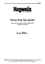
6.51e<strong>Gas</strong> <strong>Burner</strong>Ionisation monitored,Max. Heat Release 2000 kW (7,000,000 BTU)Compact design with ignition transformer and burner control,<strong>Type</strong> <strong>BR5</strong> ...for intermittend operation<strong>Type</strong> <strong>BD5</strong> …for continuous operation11/07man_br5bd5_651e_1107_ukHegwein GmbH · Am Boschwerk 7 · 70469 Stuttgart · GermanyTelefon +49 (0)711 135788-0 · Fax +49 (0)711 135788-5 · E-mail: info@hegwein.de
<strong>BR5</strong>... / <strong>BD5</strong>...Table of contents1. Part Numbering System ..........................................................................................................................32. Technical Data ........................................................................................................................................43. Design According to Dimensional Drawing .............................................................................................44. Flame monitoring.....................................................................................................................................65. Storage and Installation Instructions and Lifetime...................................................................................66. Electrical Connection...............................................................................................................................77. Functional Description of <strong>Burner</strong> Control ................................................................................................78. Program Sequence for Z725K2 and Z725K3..........................................................................................89. p, V – <strong>Gas</strong>/Air Diagrams..........................................................................................................................810. Available Spare Parts and Wear and Tear Parts ....................................................................................911. Electrodes position (top view)................................................................................................................1012. Electrical Function Test (without Flame) ...............................................................................................1013. Maintenance..........................................................................................................................................1114. Troubleshooting.....................................................................................................................................1215. Approvals...............................................................................................................................................15Note• Please read this manual and adhere to it when making use of the device• Installation and maintenance procedures may only be carried out by authorizedpersonnel• All local regulations and the prevailing codes of practice must be observed duringinstallation.• Improper installation, alignment and maintenance, as well as modifications by thecustomer, can all lead to personal injury or properly damage, as well as loss ofwarranty!2
<strong>BR5</strong>... / <strong>BD5</strong>...1. Part Numbering SystemThe example below shows how the most important burner information is incorporated into the partnumber:3
<strong>BR5</strong>... / <strong>BD5</strong>...2. Technical Data<strong>Burner</strong> PortionFuel......................................................<strong>Gas</strong>es, according to DVGW spec. sheet G 260Heat release ........................................max. 2000 kW (7,000,000 BTU)Flame length........................................max. 2,500 mm (approx. 100“)Operating mode...................................2-stage or modulatedTurn-down ratio ...................................10 : 1<strong>Burner</strong> tube ......................................... ∅ 220 mm, length see page 5<strong>Gas</strong> connection....................................2”, variable (design pressure max. 300 mbar)Air connection......................................DN150, PN16 from top, may be rotated in increments of 90°<strong>Combustion</strong> air ....................................max. 80 °CMaximum ambient temperature...........burner tube: If furnace temperatures exceed 500 °C and the burneris shut down, 20 % of the combustion air supply should be left onas a source of cooling airMaximum back pressure .....................200 mbarg inside the burner housing<strong>Burner</strong> Control ............................ approved as per DIN EN 298 for intermittent or continuousoperationPrepurge Time.....................................determined on site by furnace controlSafety Time .........................................3 seconds for flame establishmentShut-off Time.......................................< 1 second after flame failureBreak prior to restart............................> 3 secondsConnection Voltage .............................220/ 230 V, 50/ 60 Hz, fuse protection 6 A (provided by customer)Electrical connection............................Plug connectionFlame Signal (test jacks) .....................Ionisation current > 10 µAIgnition .................................................2 x 5 kV to ground (max. 2,5 sec. within safety time )Power Consumption ............................Ignition transformer 2 x 100 VA, Flame monitor 10 VAContact Load, terminal 8 .....................max. 2 A ohm.Contact Load, terminal 9 .....................max. 2 A ohm.Number of operations: max. 10 6Switch frequency: max. 10/min.Ambient Temperature..........................0 °C to + 60 °CEnclosure Rating .................................IP 54 (NEMA 4)3. Design According to Dimensional DrawingThe burner basically consists of the burner head with transformer and burner control (item 1), the burnertube with air and mounting flanges (item 6), the gas tube (item 9), the intermediate support rings withceramic insulators and the mixing unit (item 11), which consist of the outer and the inner slotted chamberwith its welded-on air-vanes.The burner tube with the connection for the air supply is threaded onto the gas flange, and may be takenoff or rotated 90° (if necessary due to the location of the air connection) after removing the 4 screws(item 4).Ignition is effected by 2 ignition electrodes (item 14). The ionisation electrode and the ignition electrodesare extended using connecting rods (item 8). These rods are led through the bottom of the transformerhousing by 3 spark-plug-type terminals (item 1.6) into the housing. With burners longer than 600 mm, theyare supported by intermediate support rings (item 7) at the gas tube in intervals of 400 mm.4
<strong>BR5</strong>... / <strong>BD5</strong>...Ø 210Standard model: transformer module enclosure rating IP 54 (NEMA 4), with plug connectionAir flange DN 150 PN 16 DIN 2633outer diameter Ø 285, bolt circle Ø 240 Mixingchamber is shown in top elevation,i.e. revolved by 90° on the burner axis.Mounting flangeOuter tube Ø 405,Bolt circle Ø 355Tube length 360 - 40002501422513*48 x 221.1120 1.1<strong>Gas</strong> 2”2 x M20 x 1.526Ø 2202 1.31.6950480519512xØ 266 7 8 10 11 13 14.1** 2 threads 1 1/2"(e.g. for external flame monitoring or inspection hole)1 Mains cable1 Signal cableAll dimensions in mm2Special model: transformer module sealed to meet IP 65 (NEMA 4x), with mains and flame signal cable<strong>Burner</strong> Sectional Drawing5
<strong>BR5</strong>... / <strong>BD5</strong>...4. Flame monitoringThe flame is monitored by an ionisation electrode which must be doused into the flame. This flame rod isenergized with an a.c. voltage. The burning flame creates a conductive connection to burner mass andacts as a rectifier for the small ionisation current. This d.c. signal is amplified in the flame monitor.The ionisation electrode and the ignition electrode are aligned according to the drawing on page 5. Theelectrode support ring is only available as one unit. The electrodes on the support ring are already bentand aligned.The internal resistance of the ionisation path is several MΩ. This high resistance requires good insulationfor the electrodes and the connecting rods. Therefore, it is important to clean the insulators more often ifthe combustion air contains dust; avoid moisture.The temperature of the ceramics must not exceed 500°C. Please see also chapter ´Technical Data;Maximum ambient temperature´.5. Storage and Installation Instructions and Lifetime<strong>Burner</strong>s are to be stored in a dry and dust-free place. Ambient temperature during storage shall be0 – 60°C. No operation and storage below dew point. Moisture must not exceed 60%. <strong>Burner</strong>s shall beprotected from mechanical damages.If the tube is longer than 3 m (approx. 118”), the burner must be provided with a guide tube. This preventsthe tube from bending too much. The end of the burner tube should protrude at least 250 mm(approx. 10”) from the end of the guide tube, if the ambient heat does not require otherwise.The gap between carrier tube and burner tube ought to be 5 mm (app. 0,2”) or more.In case of higher furnace temperatures additional cooling air may be supplied into the gap through aseparate port.The device has a limited service live. It is designed for appr. 250,000 start ups. For 50 start ups per day itslifetime would be about 10 years. This time decreases under bad conditions e.g. dust, high or lowtemperature, moisture, aggressive gases. The end user shall therefore take care that regular safetyrelated maintenance checks are carried out at site.When the appliance has reached the end of its lifetime it must be disposed of according to localregulations.6
<strong>BR5</strong>... / <strong>BD5</strong>...6. Electrical ConnectionFront Panel<strong>Burner</strong> Control 725K2 for interm. op.725K3 for cont. op.Plug Connector Pins(N)PE 1 2 3 4 5 6 7 8 9 10230V 50Hzor as appearson name platePENTrouble7Remotereset(Optional)Direct connectionor via contact of burner managementValve2Valve37Stage 2(connect if needed)LSupply voltageL1Operating voltageSafetycontactsValve 17Stage 177. Functional Description of <strong>Burner</strong> ControlFront panelAfter supplying voltage to pin 2, the system is ready for operation (LED U G is illuminated). First flip the„Automatic Operation“ toggle switch to the „I“ position. The operating or control voltage can now besupplied to pin 3 (LED U R is illuminated ). Pin 8 will automatically receive voltage, valve 1 and valve 2(stage 1) will open (LED Valve 1 is illuminated) and ignition occurs with the illumination of the LED. Aflame acknowledgement signal will be issued (yellow LED is illuminated) after a maximum of 3 secondsgiven correct flame production. The burner control switches to the operational mode, valve 3 (stage 2) (ora sequential switch) is released via pin 9, and the valve 2 LED will be illuminated.By flipping the toggle switch down, the burner control may be reset after an unsuccessful start or failure ofthe flame signal (red LED illuminated). Afterward, the burner can be restarted.A remote reset is also possible. If a button is available for this purpose, the contacts must be connected topins 3 and 5.7
<strong>BR5</strong>... / <strong>BD5</strong>...8. Program Sequence for Z725K2 and Z725K39. p, V – <strong>Gas</strong>/Air DiagramsThe pressures supplied below do not account for furnace pressure. The flow pressures are to bemeasured at each test nipple. The air pressure test nipple (item 5) is located across from the air inlet andthe gas test nipple (item 3) is across from the gas inlet. Open the test nipple by turning the inserted Allenscrew anti clockwise by 1 ½ terms. Connect the hose with pressure gauge immediately (be aware of thepressure). After measurement close test nipple by turning clockwise immediately.Heat releaseRequired quantity of air in m³/h per m³/h<strong>Gas</strong> for air factor n=1,1town gas ca. 5 kWh/ m³ Factor for town gas 5 m³/hnatural gas ca. 10 kWh/ m³ natural gas 10 m³/hpropane ca. 26 kWh/ m³ propane 26 m³/hpropane/butaneca. 30 kWh/ m³ propane/butane30 m³/hThe exact setting for the burner should be determined via flue gas measurements, with a residual oxygencontent of 3 - 5 % and CO value near zero.8
<strong>BR5</strong>... / <strong>BD5</strong>...The graphs shown are based on average values regarding gas density, gas composition, calorific value,burner version and burner tube length as well as optimised surrounding (unimpeded burn out and no backpressure in combustion chamber). The supply pressure derived from the graphs should therefore beregarded as guide numbers only. The actually required values can deviate, depending on site conditions.10. Available Spare Parts and Wear and Tear PartsItem Qty. Description Part-No. Material1 1 Ignition transformer and burnercontrol incl. ionisation flame monitorin cast housing with gas flangeBR..BD..Z 332 K 2Z 332 K 3Housing castaluminum GAl1.1 1 <strong>Burner</strong> control with front plate BR..BD..Z 725 K 2Z 725 K 3fuse 2 Amp. slow bl.P-No. ES2000TR5T1.2 1 Single ignition transformer Z 546 K 2302 1 Plug with 2 cable glands, M20x1.5 A 5 Z 1 10-pole max.2,5 mm 23 1 <strong>Gas</strong> pressure test nipple -- No spare part4 4 Allen screws -- No spare part5 1 Air pressure test nipple -- No spare part6 1 <strong>Burner</strong> tube with welded in mixingchamber with mounting flangeand air portZ 1490 Z_ _ _Stainless steel7 * Intermediate support ring with 3ceramic insulatorsZ 363 K 4Stainless steel*Qty. requireddepends on tubelength8 3 Connecting rods ∅ 3mm -- Stainless steelNo spare part9 - <strong>Gas</strong> tube ∅ 33,7 x 3,25 welded withitem 11stainless steel10 3 Ceramic insulators -- No spare part11 1 Mixing unit:Natural gasPropane/Butanemanufactured gasZ 352 Z 120Z 352 Z 80Z 352 Z 200Stainless steelStainless steelStainless steel13 1 Bolt Z728Z10 Stainless steel14 2 Ignition electrode Z 707 F 7 Adjustm. page 10Subject to wearand tear14.1 1 Ionisation electrode Z 707 F 7 Stainless steelSubject to wearand tear9
<strong>BR5</strong>... / <strong>BD5</strong>...11. Electrodes position (top view)12. Electrical Function Test (without Flame)This test diode is employed to perform a purely electrical function test.Such a test should be carried out by authorized personnel only.Caution: The gas valve must first be closed!With the aid of the test diode A10Z2 (rectifier built in to a cable), may be simulated a flame signal to theflame monitor, once power is applied. The diode must be clamped to the ionisation electrode, the otherend of the cable should make contact with burner mass (note the polarity!).Press for openingthe claw.Contact to ionisationelectrodeCaution. High voltage!Do not touch the spark electrode!To be used only for testpurposes and for a short time!Make contact,with masse.g. Igniter tubeIf still no flame signal is generated, please check:a) Is the burner control correctly wired for the supply and operating voltages?b) Has the polarity of the test diode been observed?c) Is the diode in good condition?d) Are the ionization electrode and its ceramic insulators in good condition?If no flame signal can be generated, replaced the complete burner control.10
<strong>BR5</strong>... / <strong>BD5</strong>...13. MaintenanceThe units do not require special maintenance. However they should be tested for proper function at certainintervals (for instance after 3 months). Keep attention to mechanical lifetime of burner control.This test has to be carried out in shorter periods if the burners are operated with dusty combustion airsince electrically conductive dirt deposits or moisture on the ceramic insulators of the burners might resultin a breakdown of service. The ionisation circuit has an inner resistance of several MΩ. Undamaged andclean ceramic insulators are therefore a necessary prerequisite.Replacement Parts ( please see dimensional drawing on page 5)1. <strong>Burner</strong> Head<strong>Burner</strong> control (item 1.1) and ignition transformer (item 1.2) can be replaced individually.2. <strong>Burner</strong> TubeAfter removing the four screws (item 4) on the gas flange, the entire gas tube may be removed.3. Electrodes (subjects to wear and tear, exempted from manufacturer´s warranty)Ceramics as well as Ignition and Ionisation electrodes are individually removable.The ionization electrode remains unbent, and should be cut off in a distance of 30 mm longer than bolt tip.Cut the ignition electrode to length and bend 180° up toward the inner slotted disc, leaving a gap ofapprox. 2 - 3 mm.4. Intermediate support rings (for tube lengths greater than 600 mm)Remove the igniter tube and the complete mixing unit. Loosen the locking screw of each support ring andremove them from the tube. Slide on the new intermediate support rings. Finally, mount the completemixing unit. The intermediate support rings should be placed at intervals of 400 mm from one another andinsert the connecting rods. Tighten all locking screws on the support rings, while observing that the rodsdo not become twisted.11
<strong>BR5</strong>... / <strong>BD5</strong>...14. TroubleshootingThe following items have to be carried out step by step14.1 Spark cannot be seenPossible Causes:Possible Reasons/ Remedy.1 Ignitor has not been energized .1.1 Remedy: Check wiring.Check BMS..2 Spark surpresses the ionisationsignal.(Visual check in dark surroundingwith fuel valves closed.Caution: do not touch high voltageelectrode.).2.1 Ignition electrode internals has been burnt awayRemedy: replace electrode, clean ignitor / burner internalsand verify the correct spark gap..2.2 Electrode distance to large or has a short circuitRemedy: clean ignitor / burner internals, replace wornparts and verify the correct spark gap of 2-3 mm..2.3 Spark transformer faultyRemedy: Replace spark transformer..2.4 Tinder on the ignition electrode or ground rod / bolt.Remedy: clean ignitor / burner internals, and remove layerwith emery cloth..2.5 Ceramic insulator is broken(De-energize the ignitor/ burner.Remove outer tube.)Remedy: Replace ceramic insulator.14.2 Flame cannot be seenPossible Causes:.1 No combustion air.(Check pressure at test nipple).Possible Reasons / Remedy.1.1 Sleeves or valves are completely closed.Flap or valve does not work..1.2 Pipe is clogged..2 No fuel(Check pressure at test nipple)..2.1 Fuel pipe too long.Remedy: Install valve close to <strong>Burner</strong>/ Ignitor..2.2 Fuel pipe inert with nitrogen.Remedy: Start the ignitor/ burner several times to get theinert gas removed and replaced by fuel..2.3 Shut off valve is out of order.Remedy: Replace fuel valve..3 Air/Fuel ratio not correct.(Check fuel and air pressure at testnipple).3.1 Check correct fuel and air pressure adjustment.Use diagram values given in ignitor/ burner manual..3.2 Correct fuel type?.3.3 Clean combustion air?12
<strong>BR5</strong>... / <strong>BD5</strong>...14.3 Flame can be seen but no flame signal present after safety ignition timehas elapsedPossible Causes:Possible Reasons / Remedy.1 No ionisation signal.(Visual check with fuel valvesclosed and de-energizedignitor/ burner.).2 <strong>Burner</strong>/Ignitor has been exposed toexcessive temperature fromcombustion chamber during <strong>Burner</strong>/Ignitor stand still. Ceramics are toohot, the insulation resistance hasdropped to a value that is too low..3 The setting of the fuel and airpressures at the burner/ignitor arenot correct. Flame root is not in thearea of the lonisation electrode..4 After failure correction of item1- 3a flame signal is still not available.If flame signal is still not reportedthough step 1 to 5 have beenverified..1.1 Ionisation electrode has been burnt away.Remedy: Replace electrode and verify the correct sparkgap..1.2 Ceramic insulator is broken.Remedy: Replace insulator..2.1 Leave blower air fully on or in cooling stage while theburner/ignitor is switched off..3.1 Adjustment and correction of the corresponding devices.Use diagram values as given in the available manual..3.2 Flame is pushed out of the ignitor/ burner mouth : Fuel or/and air flow insufficient..4.1 Remedy: Check complete wiring with test diode A10Z2.See manual.14.4 Shut off during operationPossible Causes:.1 Varying back pressures or supplypressures cause the flame to trip.Possible Reasons / remedy.1.1 Check pressure at the test nipples. Fluctuations require adifferential pressure regulator on the air and fuel supplyside..1.2 <strong>Burner</strong> or ignitor test should be carried out outsidecombusstion chamber.Local safety regulations must be observed..2 Pilot flame is strongly influenced orwhen suffocated by the main flame..2.1 Remedy: Change position.2.2 Remedy: A more powerful burner/ ignitor may berequested.14.5 Automatic shut-down at start-up when a flame is reported before theignition fuel valve have been openedPossible Causes:Possible Reasons / remedy.1 Flame has not extinguished afterthe previous shut-down due to aleaking valve and is still presentwhen system is restarted..1.1 Remedy : Replace valve.13
<strong>BR5</strong>... / <strong>BD5</strong>...14.6 Electrical Malfunction.1 <strong>Burner</strong> control does not start .1.1 Remedy: Devices of a different make can cause trouble.See chapter..2 <strong>Burner</strong>/ Ignitor burner control are inoperation but the release contactdoes not work..2.1 Check built in fuse (2AT).In case of questions please give us the exact type designation as given on the nameplate.14
<strong>BR5</strong>... / <strong>BD5</strong>...15. Approvals15
<strong>BR5</strong>... / <strong>BD5</strong>...16
<strong>BR5</strong>... / <strong>BD5</strong>...17